differential DATSUN B110 1973 Service Repair Manual
[x] Cancel search | Manufacturer: DATSUN, Model Year: 1973, Model line: B110, Model: DATSUN B110 1973Pages: 513, PDF Size: 28.74 MB
Page 67 of 513
r
r
QRr
S
IJ
lrll
r
W
bI15
I
Q
ll
rrll
l
0
fl
AU
1
i
L
Ill
J
cr
U
J
r
Jj
I
DATSUN
1200
MODEL
B
11
0
SERIES
L
NISSAN
I
NISSAN
MOTOR
CO
LTD
TOKYO
JAPAN
I
I
i
I
I
I
SECTION
PD
PROPELLER
SHAFT
DIFFERENTIAL
CARRIER
PROPELLER
SHAFT
AND
UNIVERSAL
JOINT
DIFFERENTIAL
CARRIER
PD
1
PD
4
Page 68 of 513
PROPELLER
SHAFT
DIFFERENTIAL
CARRIER
PROPELLER
SHAFT
AND
UNIVERSAL
JOINT
CONTENTS
DESC
R
I
PTI
ON
REMOVAL
DISASSEMBL
Y
INSPECTION
ASSEMBL
Y
PD
PD
2
PD
2
PD
2
PD
2
SERVICE
DATA
AND
SPECIFICATIONS
TROUBLE
DIAGNOSES
AND
CORRECTIONS
PD
3
PD
3
j
j
lI
ID
1
Assembly
yoke
sleeve
2
As
mbly
journal
with
lever
3
Ring
snap
bearing
race
4
Assembly
race
bearing
5
Assembly
journal
with
bearing
6
Yoke
flange
7
Ring
snap
bearing
race
8
Assembly
race
bearing
9
Bolt
10
Washer
lock
11
Nut
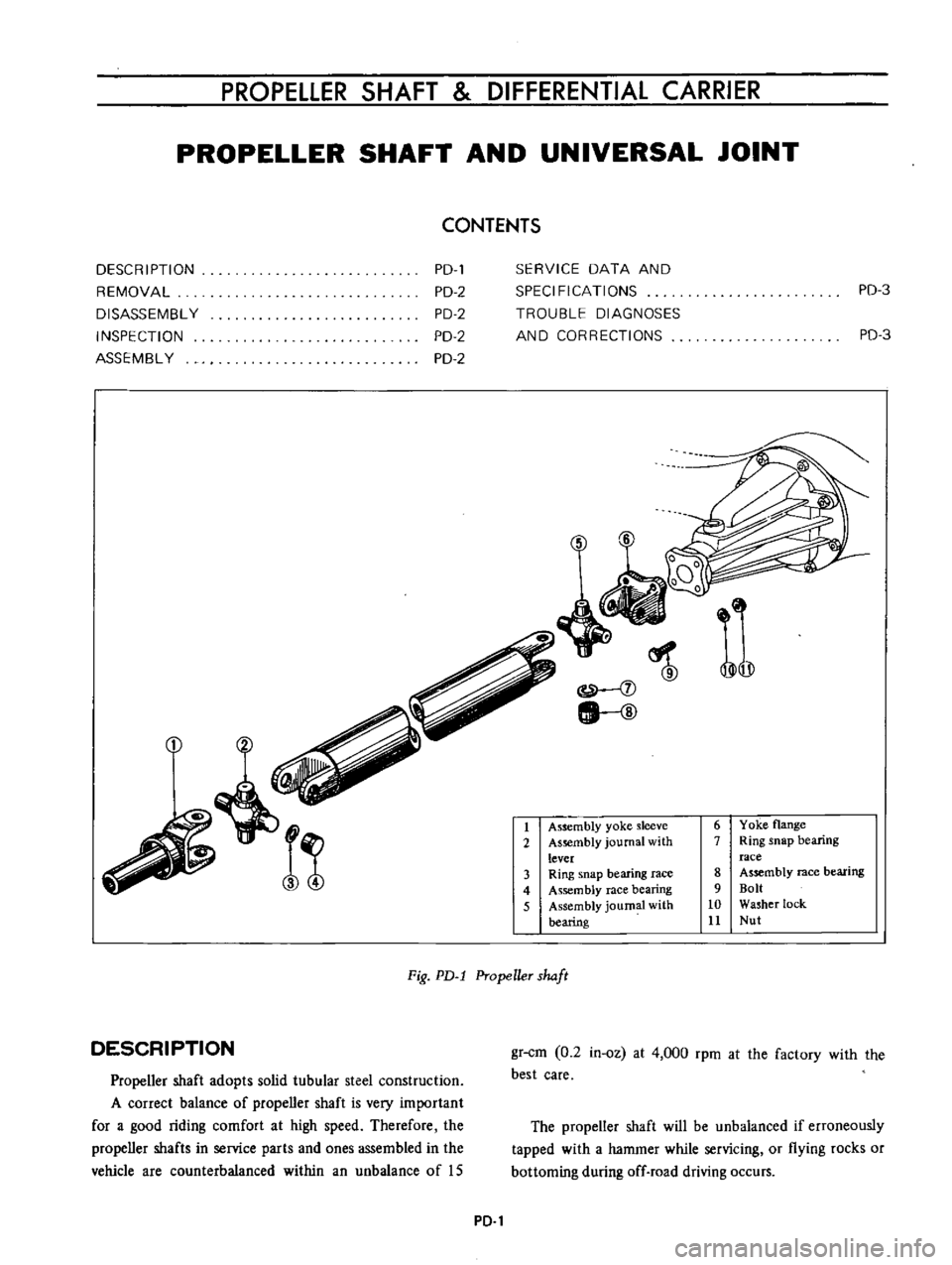
Fig
PD
l
Propeller
shaft
DESCRIPTION
Propeller
shaft
adopts
solid
tubular
steel
construction
A
correct
balance
of
propeller
shaft
is
very
important
for
a
good
riding
comfort
at
high
speed
Therefore
the
propeller
shafts
in
service
parts
and
ones
assembled
in
the
vehicle
are
counterbalanced
within
an
unbalance
of
IS
gr
cm
0
2
in
oz
at
4
000
rpm
at
the
factory
with
the
best
care
The
propeller
shaft
will
be
unbalanced
if
erroneously
tapped
with
a
hammer
while
servicing
or
flying
rocks
or
bottoming
during
off
road
driving
occurs
PD
1
Page 70 of 513
PROPELLER
SHAFT
DIFFERENTIAL
CARRIER
Insert
the
journal
into
the
yoke
flange
Tap
the
journal
bearing
into
the
yoke
flange
using
a
brass
drift
smaller
than
the
hole
in
the
yoke
Tap
the
other
bearing
into
the
opposite
end
of
the
yoke
flange
until
the
bearing
is
in
line
with
the
snap
ring
grooves
With
a
pair
of
pliers
install
the
snap
rings
on
both
ends
of
the
yoke
flange
Insert
the
flange
assembly
in
the
sleeve
yoke
Place
the
other
yoke
bearing
into
the
opposite
end
of
the
yoke
and
tap
this
bearing
into
the
yoke
until
the
bearing
is
in
line
with
the
snap
ring
grooves
Install
the
snap
rings
on
both
ends
of
the
yoke
When
all
parts
are
assembled
check
the
spider
and
surroundings
for
tightness
When
the
clearance
is
excessive
adjust
with
over
size
snap
rings
as
follows
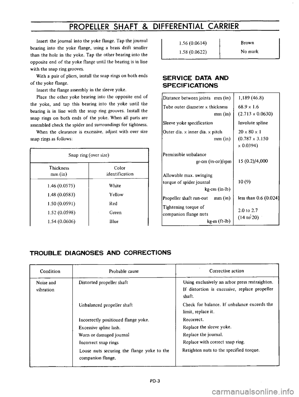
Snap
ring
over
size
Thickness
Color
mrn
in
identification
I
46
0
0575
White
I
48
0
0583
Yellow
1
50
0
0591
Red
1
52
0
0598
Green
1
54
0
0606
Blue
1
56
0
0614
1
58
0
0622
SERVICE
DATA
AND
SPECIFICATIONS
Distance
between
joints
mm
in
Tube
outer
diameter
x
thickness
mm
in
Sleeve
yoke
specification
Outer
dia
x
inner
dia
x
pitch
mm
in
Brown
No
mark
I
189
46
8
68
9
x
1
6
2
713
x
0
0630
Involute
spline
20
x
80
x
I
0
787
x
3
150
x
0
0394
Permissible
unbalance
gr
cm
in
oz
rpm
15
0
2
4
000
Allowable
max
swinging
torque
of
spider
journal
10
9
kg
cm
in
lb
Propeller
shaft
run
out
mm
in
Tightening
torque
of
companion
flange
nuts
kg
m
ft
Ib
TROUBLE
DIAGNOSES
AND
CORRECTIONS
Condition
Probable
cause
Noise
and
vibration
Distorted
propeller
shaft
Unbalanced
propeller
shaft
Corrective
action
less
than
0
6
0
024
2
0
to
2
7
I4
to
20
Using
exclusively
an
arbor
press
restraighten
If
distortion
is
excessive
replace
propeller
shaft
Check
for
balance
If
unbalance
exceeds
the
limit
replace
it
Recorrect
Replace
the
sleeve
yoke
Replace
the
journal
Replace
with
correct
snap
ring
Retighten
nuts
to
the
specified
torque
Incorrectly
positioned
flange
yoke
Excessive
spline
lash
Worn
or
damaged
journal
Inconect
snap
rings
Loose
nuts
securing
the
flange
yoke
to
the
companion
flange
PD
3
Page 71 of 513
CHASSIS
DIFFERENTIAL
CARRIER
CONTENTS
DESCRIPTION
REMOVAL
DISASSEMBL
Y
INSPECTION
AND
REPAIR
ASSEMBLY
AND
ADJUSTMENT
Assembling
differential
gear
case
Setting
and
adjusting
drive
pinion
PD
4
PD
5
PD
5
PD
7
PD
8
PD
9
PD
10
Adjusting
drive
pinion
preload
Setting
and
adjusting
side
bearing
shims
INSTALLATION
TROUBLE
DIAGNOSES
AND
CORRECTIONS
SERVICE
DATA
AND
SPECIFICATIONS
DESCRIPTION
Apply
chassis
grease
to
oil
seal
lip
when
assembling
Tightening
torque
of
drive
pinion
nut
12
to
17
kg
m
86
8
to
122
9
ft
Ib
A
correct
contact
pattern
means
that
it
lies
in
the
range
of
213
to
3
4
from
the
tip
of
the
tooth
under
no
load
Backlash
is
O
10
to
0
15mm
10
0039
to
0
0059
in
Pinion
bearing
adjust
spacer
Tightening
torque
of
drive
gear
bolt
6
0
to
7
0
kg
m
43
4
to
50
6
ft
Ibl
Tighten
by
tapping
bolt
head
with
a
0
1
kg
1
4
Ib
hammer
Drive
pinion
adjusting
washer
T
W
N
IH
xO
OlJ
O
21mml
Side
gear
thrust
washer
Left
side
T1
A
C
0
H
j
x
0
01
0
200
E
mm
Right
side
T2
B
0
H
0
01
0
200
F
mm
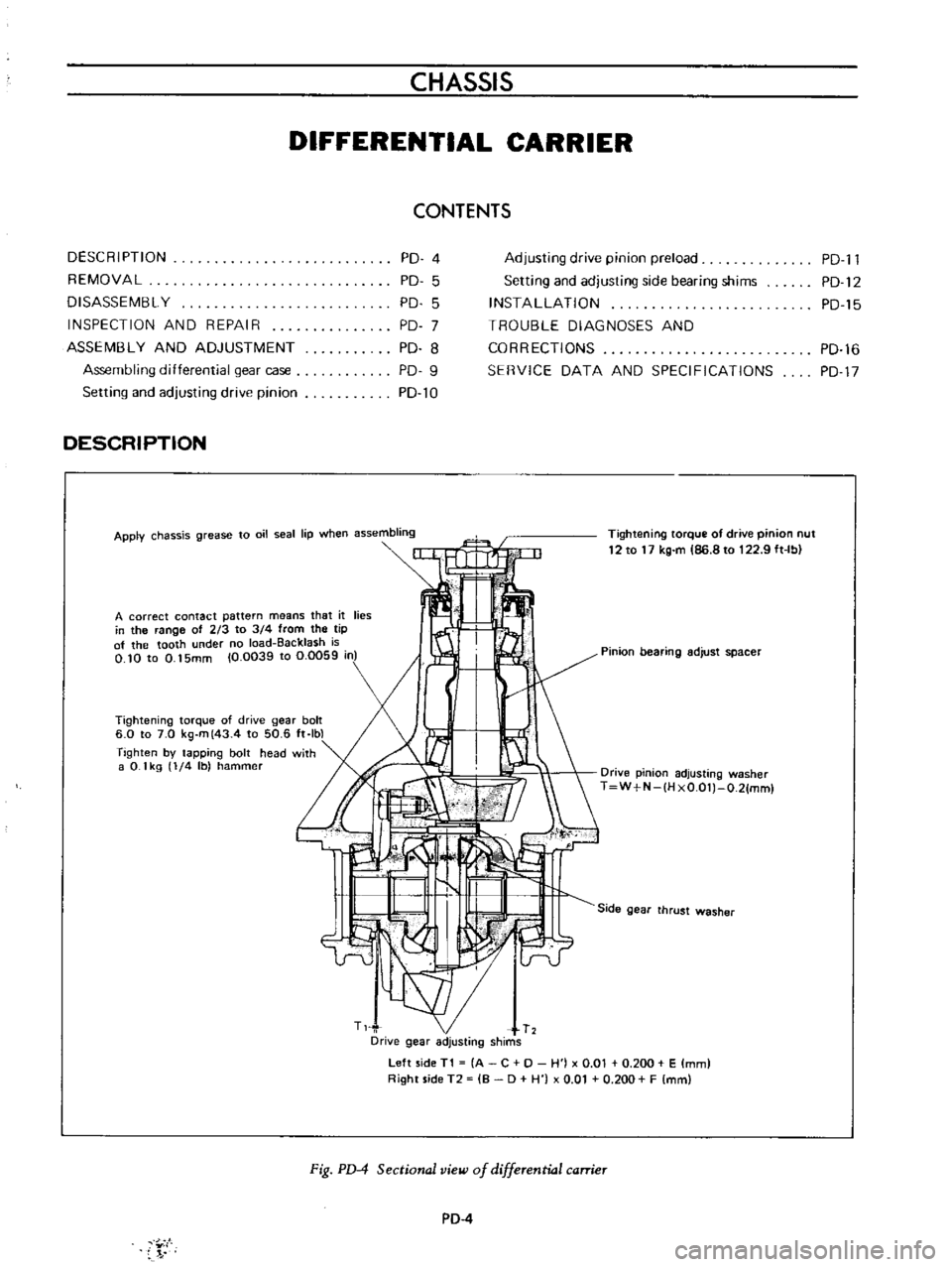
Fig
PD
4
Sectional
view
of
differential
carrier
PD
4
Y
I
PD
l1
PD
12
PD
15
PD
16
PD
17
Page 72 of 513
PROPELLER
SHAFT
DIFFERENTIAL
CARRIER
The
gear
carrier
is
made
of
light
and
strong
aluminum
alloy
metal
and
hypoid
bevel
gear
is
used
Adjust
drive
pinion
bearing
preload
with
non
adjusting
type
spacer
and
pinion
height
and
side
bearing
adjust
ment
with
spacer
shim
s
Millimeter
standardization
stilI
remains
for
all
the
screw
threads
of
this
unit
Therefore
adjustment
figures
stamped
on
screws
adjusting
shims
washers
differential
case
drive
pinion
and
carrier
are
in
millimeters
in
accordance
with
the
millimeter
standardization
of
parts
The
proper
lubrication
to
the
gear
housing
is
necessary
otherwise
it
would
shorten
the
durability
of
the
gear
and
cause
other
troubles
The
lubricant
should
be
checked
each
5
000
km
3
000
miles
and
replenished
each
50
000
km
30
000
miles
The
lubricant
should
be
drained
and
ref11led
at
the
end
of
the
first
1
000
km
600
miles
to
eliminate
any
loose
material
from
the
sump
which
results
from
breaking
Differential
lubricant
should
be
changed
at
least
every
50
000
km
30
000
miles
ConsIderations
should
be
given
to
the
following
matters
I
Nominated
hypoid
gear
oil
must
be
used
2
It
is
prohibited
to
use
any
gear
oil
of
different
viscosity
The
same
brand
must
always
be
selected
3
The
standard
oil
capacity
is
about
0
75
liter
0
198
US
gal
REMOVAL
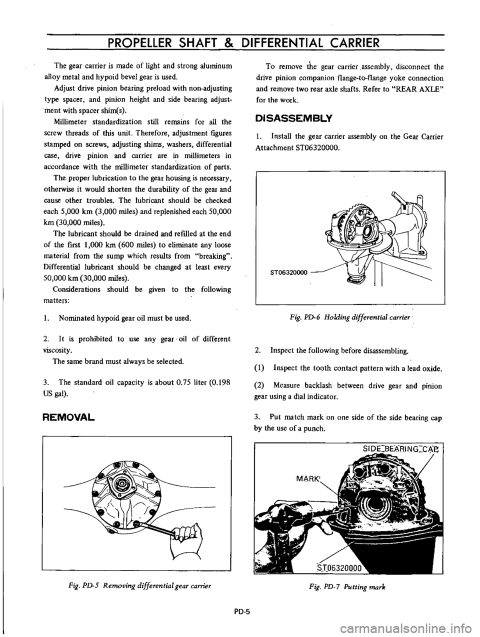
Fig
PD
5
Removing
differential
gear
carrier
To
remove
the
gear
carrier
assembly
disconnect
the
drive
pinion
companion
flange
te
flange
yoke
connection
and
remove
two
rear
axle
shafts
Refer
to
REAR
AXLE
for
the
work
DISASSEMBLY
I
Install
the
gear
carrier
assembly
on
the
Gear
Carrier
Attachment
ST06320000
ST06320000
Fig
PD
6
Holding
differential
camer
2
Inspect
the
following
before
disassembling
I
Inspect
the
tooth
contact
pattern
with
a
lead
oxide
2
Measure
backlash
between
drive
gear
and
pinion
gear
using
a
dial
indicator
3
Put
match
mark
on
one
side
of
the
side
bearing
cap
by
the
use
of
a
punch
SIDCBEMING
c
e
Fig
PD
7
Putting
mark
PD
5
Page 73 of 513
CHASSIS
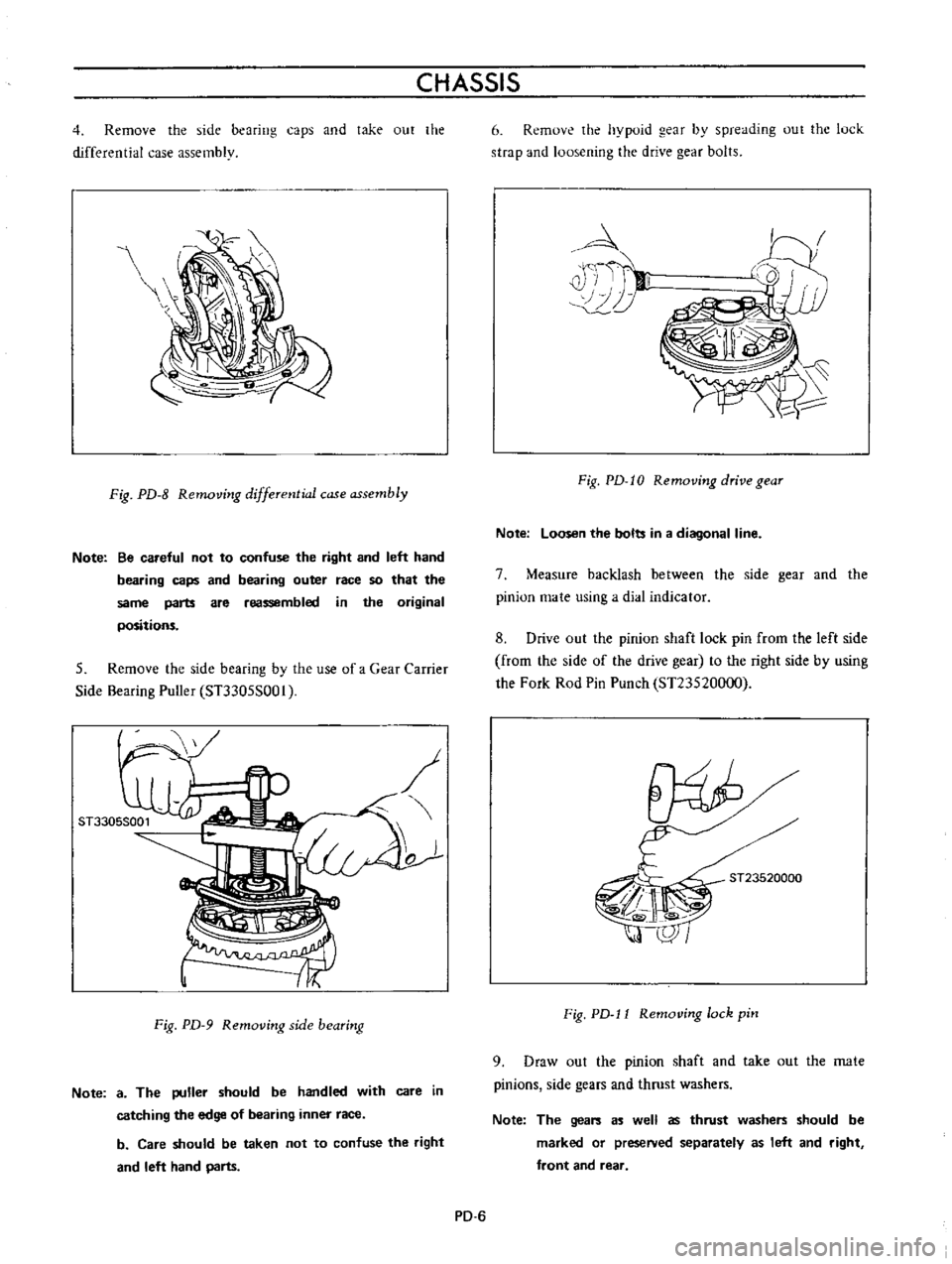
4
Remove
the
side
bearing
caps
and
take
out
the
differential
case
assembly
Fig
PD
8
Removing
differential
case
assembly
Note
Be
careful
not
to
confuse
the
right
and
left
hand
bearing
caps
and
bearing
outer
race
so
that
the
same
parts
are
reassembled
in
the
original
positions
5
Remove
the
side
bearing
by
the
use
of
a
Gear
Carrier
Side
Bearing
Puller
ST3305S001
o
Fig
PD
9
Removing
side
bearing
Note
a
The
puller
should
be
handled
with
care
in
catching
the
edge
of
bearing
inner
race
b
Care
should
be
taken
not
to
confuse
the
right
and
left
hand
parts
6
Remove
the
hypoid
gear
by
spreading
out
the
luck
strap
and
loosening
the
drive
gear
bolts
4
i
T
II
10
Fig
PD
I0
Removing
drive
gear
Note
Loosen
the
bolts
in
a
diagonal
line
7
Measure
backlash
between
the
side
gear
and
the
pinion
mate
using
a
dial
indicator
8
Drive
out
the
pinion
shaft
lock
pin
from
the
left
side
from
the
side
of
the
drive
gear
to
the
right
side
by
using
the
Fork
Rod
Pin
Punch
ST23520000
ST23520000
Fig
PD
l1
Removing
lock
pin
9
Draw
out
the
pinion
shaft
and
take
out
the
mate
pinions
side
gears
and
thrust
washers
Note
The
gears
as
well
as
thrust
washers
should
be
marked
or
preseNed
separately
as
left
and
right
front
and
rear
PD
6
Page 74 of 513
PROPELLER
SHAFT
DIFFERENTIAL
CARRIER
10
Measure
the
initial
turning
torque
drive
pinion
gear
by
using
Drive
Pinion
Preload
Gauge
Sn127S000
11
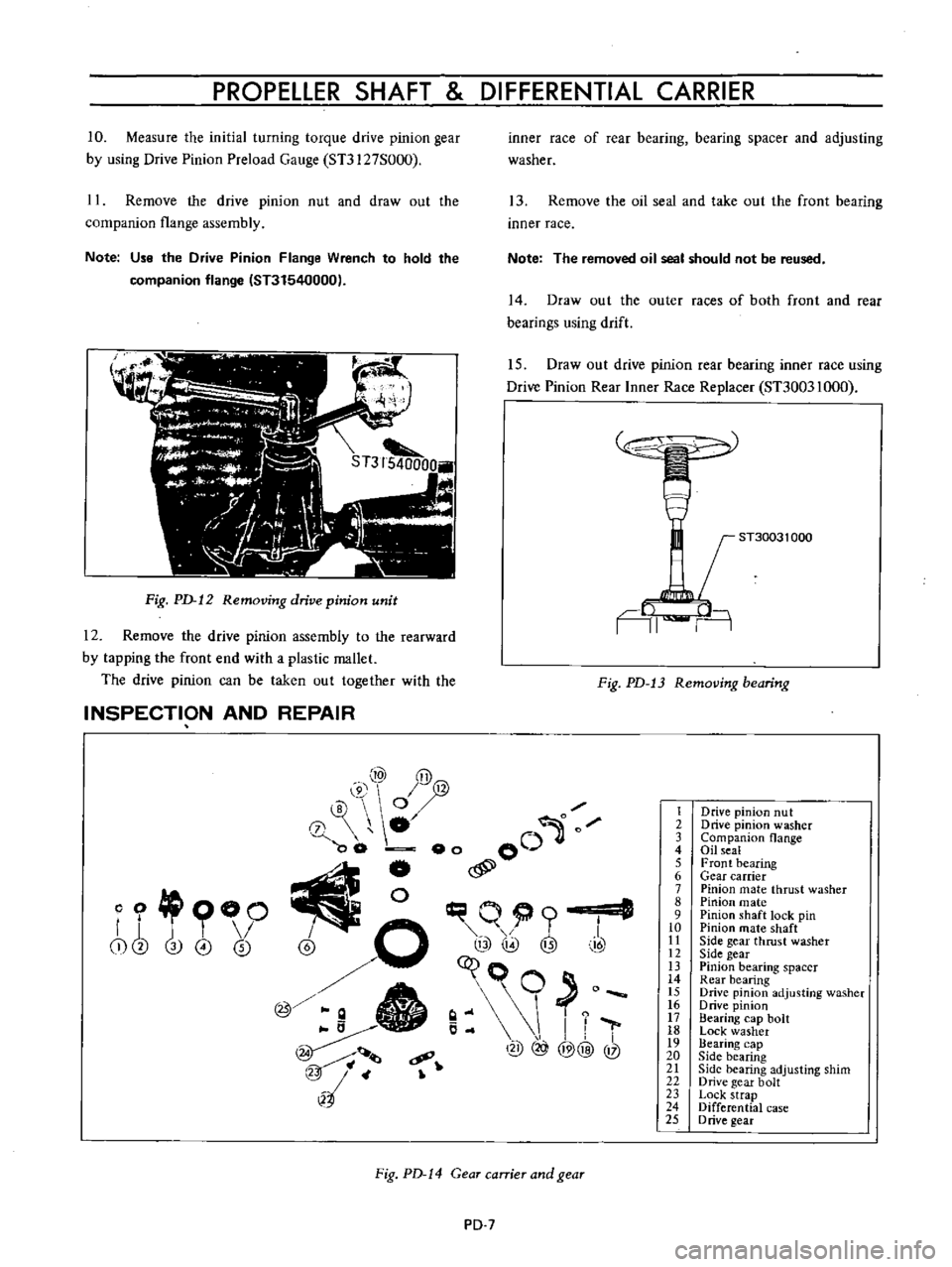
Remove
the
drive
pinion
nut
and
draw
out
the
companion
flange
assembly
Note
Use
the
Drive
Pinion
Flange
Wrench
to
hold
the
companion
flange
IST31540000
Fig
PD
12
Removing
drive
pinion
unit
12
Remove
the
drive
pinion
assembly
to
the
rearward
by
tapping
the
front
end
with
a
plastic
mallet
The
drive
pinion
can
be
taken
out
together
with
the
INSPECTION
AND
REPAIR
inner
race
of
rear
bearing
bearing
spacer
and
adjusting
washer
13
Remove
the
oil
seal
and
take
out
the
front
bearing
inner
race
Note
The
removed
oil
seal
should
not
be
reused
14
Draw
out
the
outer
races
of
both
front
and
rear
bearings
using
drift
15
Draw
out
drive
pinion
rear
bearing
inner
race
using
Drive
Pinion
Rear
Inner
Race
Replacer
ST30031000
ST30031
000
AI
n
Fig
PD
13
Removing
bearing
10
y@
@
0
0
0
00
eo
00
j
l
I
@
o
q@
@
t
I
7
c9
@
@@
@
l2
4
o
OO
r
j
T
I
i
cb
3
0
0
Fig
PD
14
Gear
carrier
and
gear
PD
7
1
2
3
4
S
6
7
8
9
10
II
12
IJ
14
IS
16
17
18
19
20
21
22
23
24
25
Drive
pinion
nut
Drive
pinion
washer
Companion
flange
Oil
seal
Front
bearing
Gear
carrier
Pinion
mate
thrust
washer
Pinion
mate
Pinion
shaft
lock
pin
Pinion
mate
shaft
Side
gear
thrust
washer
Side
gear
Pinion
bearing
spacer
Rear
bearing
Drive
pinion
adjusting
washer
o
rive
pinion
Bearing
cap
bolt
Lock
washer
Bearing
cap
Side
bearing
Side
bearing
adjusting
shim
Drive
gear
bolt
Lock
strap
Differential
case
D
rive
gear
Page 75 of 513
CHASSIS
Before
inspecting
various
parts
thoroughly
wash
them
so
that
damage
and
wear
can
be
easily
detected
Then
proceed
as
follows
Check
gear
teeth
for
scoring
cracking
and
chipping
and
make
sure
that
tooth
pattern
indicates
correct
meshing
depth
If
any
defect
is
evident
replace
parts
as
required
Note
Drive
pinion
and
drive
gear
are
supplied
for
replacement
as
a
set
therefore
should
either
part
be
damaged
replace
as
a
set
Check
the
pinion
gear
shaft
and
pinion
gear
mating
faces
for
scoring
and
signs
of
wear
and
replace
as
required
Follow
the
same
procedure
for
inner
faces
of
side
gear
and
their
seats
on
differential
case
3
Inspect
all
bearing
races
and
rollers
for
scoring
chipping
or
evidence
of
excessive
wear
They
should
be
in
tiptop
condition
not
worn
with
mirror
like
surfaces
Replace
if
there
is
a
doubt
on
their
efficiency
since
an
incorrect
bearing
operation
may
result
in
noisiness
and
gear
seizure
4
Inspect
thrust
washer
faces
Small
defects
can
be
corrected
with
emery
paper
In
ASSEMBLY
AND
AD
JUSTMENT
Tightening
torque
of
side
bearing
cap
bolts
5
to
6kg
m
36
2
to
43
4
ft
lb
co
g
E
E
on
N
case
the
clearance
between
the
side
gear
and
thrust
washer
exceeds
0
2
mm
0
0079
in
replace
the
thrust
washers
Three
kinds
of
thrust
washers
are
available
5
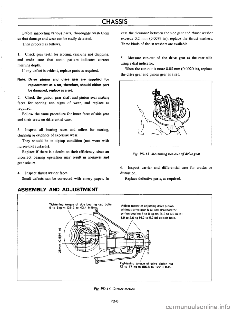
Measure
run
out
of
the
drive
gear
at
the
rear
side
using
a
dial
indicator
When
the
run
out
is
more
0
05
mm
0
0020
in
replace
the
drive
gear
and
pinion
gear
as
a
set
Fig
PD
15
Measuring
run
out
of
drive
gear
6
Inspect
carrier
and
differential
case
for
cracks
or
distortion
Replace
defective
parts
as
required
Adjust
spacer
of
adjusting
drive
pinion
without
drive
gear
oil
seal
Preload
for
pinion
bearing
6
to
8
kg
em
5
2
to
6
9
in
Ib
1
9
to
2
6
kg
4
2
to
5
7
Ib
at
bolt
hole
1
Tightening
torque
of
drive
pinion
nut
12
to
17
kg
m
86
8
to
122
9
ft
Ibl
Fig
PD
16
Carrier
section
PO
8
Page 76 of 513
PROPELLER
SHAFT
DIFFERENTIAL
CARRIER
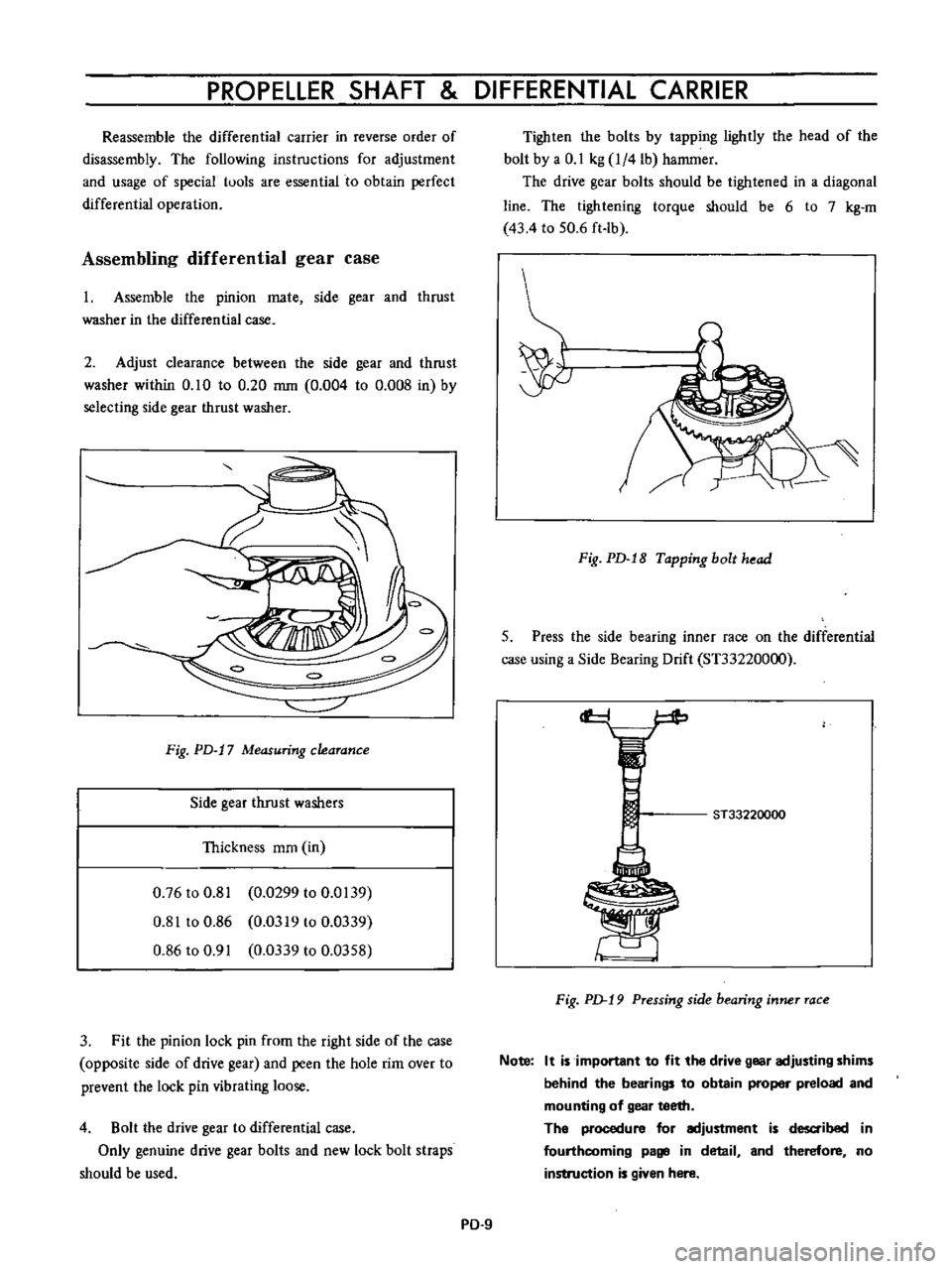
Reassemble
the
differential
carrier
in
reverse
order
of
disassembly
The
following
instructions
for
adjustment
and
usage
of
special
tuols
are
essential
to
obtain
perfect
differential
operation
Assembling
differential
gear
case
1
Assemble
the
pinion
mate
side
gear
and
thrust
washer
in
the
differential
case
2
Adjust
clearance
between
the
side
gear
and
thrust
washer
within
0
10
to
0
20
mm
0
004
to
0
008
in
by
selecting
side
gear
thrust
washer
Fig
PD
17
Measuring
clearance
Side
gear
thrust
washers
Thickness
mm
in
0
76
to
0
81
0
0299
to
0
0139
0
81
to
0
86
0
0319
to
0
0339
0
86
to
0
91
0
0339
to
0
0358
3
Fit
the
pinion
lock
pin
from
the
right
side
of
the
case
opposite
side
of
drive
gear
and
peen
the
hole
rim
over
to
prevent
the
lock
pin
vibrating
loose
4
Bolt
the
drive
gear
to
differential
case
Only
genuine
drive
gear
bolts
and
new
lock
bolt
straps
should
be
used
Tighten
the
bolts
by
tapping
lightly
the
head
of
the
bolt
by
a
0
1
kg
l
4lb
hammer
The
drive
gear
bolts
should
be
tightened
in
a
diagonal
line
The
tightening
torque
should
be
6
to
7
kg
m
43
4
to
50
6
ft
lb
Fig
PD
18
Tapping
bolt
head
5
Press
the
side
bearing
inner
race
on
the
differential
case
using
a
Side
Bearing
Drift
ST33220000
cf
ST33220000
F
ig
p
19
Pressing
side
bearing
inner
race
Note
It
is
important
to
fit
the
drive
gear
adjusting
shims
behind
the
bearings
to
obtain
proper
preload
and
mounting
of
gear
teeth
The
procedure
for
adjustment
is
d
ibed
in
fourthcoming
page
in
detail
and
therefore
no
instruction
is
given
here
PD
9
Page 78 of 513
PROPELLER
SHAFT
DIFFERENTIAL
CARRIER
6
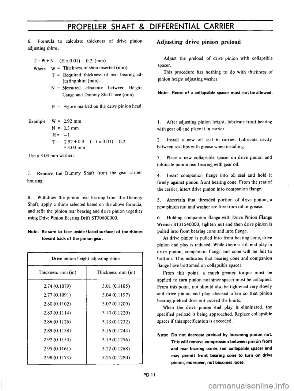
Formula
to
calculate
thickness
of
drive
pinion
adjusting
shims
T
W
N
H
x
0
01
0
2
mm
Where
W
Thickness
of
shim
inserted
mm
T
Required
thickness
of
rear
bearing
ad
justing
shim
mm
N
Measured
clearance
between
Height
Gauge
and
Dummy
Shaft
face
mm
H
Figure
marked
on
the
drive
pinion
head
Example
W
2
92
mm
N
0
3
mm
H
1
T
2
92
0
3
1
x
0
01
0
2
3
03
mm
Use
a
3
04
mm
washer
7
Remove
the
Dummy
Shaft
from
the
gear
carrier
housing
8
Withdraw
the
pinion
rear
bearing
from
the
Dummy
Shaft
apply
a
shims
selected
based
on
the
above
formula
and
refit
the
pinion
rear
bearing
and
drive
pinion
together
using
Drive
Pinion
Bearing
Drift
STJ0600000
Note
Be
sure
to
face
inside
faced
surface
of
the
shimes
toward
back
of
the
pinion
gear
Drive
pinion
height
adjusting
shims
Thickness
mm
in
Thickness
mm
in
2
74
0
1079
2
77
0
i091
2
80
0
1102
2
83
0
1114
2
86
0
1126
2
89
0
1138
2
92
0
1150
2
95
0
1161
2
98
0
1173
3
01
0
1185
3
04
0
1197
3
07
0
1209
3
10
0
i
220
3
13
0
1232
3
16
0
1244
319
0
1256
3
22
0
1268
3
25
0
1280
PD
Adjusting
drive
pinion
preload
Adjust
the
preload
of
drive
pinion
with
collapsible
spacer
This
procedure
has
nothing
to
do
with
thickness
of
pinion
height
adjusting
washer
Note
Reuse
of
a
collapsible
spacer
must
not
be
allowed
After
adjusting
pinion
height
lubricate
front
bearing
with
gear
oil
and
place
it
in
carrier
2
Install
a
new
oil
seal
in
carrier
Lubricate
cavity
between
seal
lips
with
grease
when
installing
3
Place
a
new
collapsible
spacer
on
drive
pinion
and
lubricate
pinion
rear
bearing
with
gear
oil
4
Insert
companion
flange
into
oil
seal
and
hold
it
firmly
against
pinion
fron
bearing
cone
From
the
rear
of
the
carrier
insert
drive
pinion
into
companion
flange
5
Ascertain
that
threaded
portion
of
drive
pinion
a
new
pinion
nut
and
washer
are
free
from
oil
or
grease
6
Holding
companion
flange
with
Drive
Pinion
Flange
Wrench
ST31540000
tighten
nut
and
then
drive
pinion
is
pulled
into
front
bearing
cone
and
into
flange
As
drive
pinion
is
pulled
into
front
bearing
cone
drive
pinion
end
play
is
reduced
While
there
is
still
end
play
in
drive
pinion
companion
flange
and
cone
will
be
felt
to
bottom
This
indicates
that
bearing
cone
and
companion
flange
have
bottomed
on
collapsible
spacer
From
this
point
a
much
greater
torque
must
be
applied
to
turn
pinion
nut
since
spacer
must
be
collapsed
From
this
point
nut
should
also
be
tightened
very
slowly
and
drive
pinion
end
play
checked
often
so
that
pinion
bearing
preload
does
not
exceed
the
limits
When
the
drive
pinion
end
play
is
eliminated
the
specified
preload
is
being
approached
Replace
collapsible
spacer
if
this
specification
is
exceeded
Note
Do
not
decrease
preload
by
loosening
pinion
nut
This
will
remove
compression
between
pinion
front
and
rear
bearing
cones
and
collapsible
spacer
and
may
permit
front
bearing
cone
to
turn
on
drive
pinion
moreover
nut
becomes
loose