fuel filter DATSUN B110 1973 Service Repair Manual
[x] Cancel search | Manufacturer: DATSUN, Model Year: 1973, Model line: B110, Model: DATSUN B110 1973Pages: 513, PDF Size: 28.74 MB
Page 306 of 513
EMISSION
CONTROL
AND
TUNE
UP
EMISSION
CONTROL
SYSTEM
AN
D
ENGINE
TUNE
UP
CONTENTS
BASIC
MECHANICAL
SYSTEM
ET
Checking
and
adjusting
dash
pot
Adjusting
intake
and
exhaust
valve
automatic
transmission
model
only
ET
9
clearances
ET
1
Checking
carburetor
return
spring
ET
9
Checking
and
adjustin9
drive
belt
ET
2
Checking
choke
mechanism
choke
valve
Retightening
cylinder
head
bolts
manifold
and
linkagel
ET
9
nuts
and
carburetor
securing
nuts
ET
2
Checking
anti
dieseling
solenoid
ET
9
Checking
engine
oil
ET
2
Replacing
fuel
filter
ET
10
Replacing
oil
filter
ET
3
Checking
fuel
lines
hoses
pipings
Changing
engine
coolant
L
L
C
ET
3
connections
etc
ET10
Checking
cooling
system
hoses
and
THROTTLE
OPENER
CONTROL
SYSTEM
ET
10
connections
ET
4
Checking
and
adjusting
throttle
opener
ET
13
Checking
vacuum
fittings
hoses
and
TRANSMISSION
CONTROLLED
VACUUM
connections
ET
4
ADVANCE
SYSTEM
ET
17
Checking
engine
compression
ET
4
Checking
electrical
advance
control
system
ET
19
Checking
exhaust
manifold
heat
control
AUTOMATIC
TEMPERATURE
CONTROL
AIR
valve
ET
5
CLEANER
A
T
C
AIR
CLEANER
ET
20
IGNITION
AND
FUEL
SYSTEM
ET
5
Replacing
carburetor
air
cleaner
filter
ET
20
Checking
battery
ET
5
Checking
hot
air
control
valve
ET
20
Checking
and
adjusting
ignition
timing
ET
5
CRANKCASE
EMISSION
CONTROL
Checking
or
replacing
distributor
breaker
SYSTEM
ET
22
point
condenser
and
spark
plugs
ET
6
Checking
or
replacing
PCV
valve
ET
23
Checking
distributor
ignition
wiring
and
Checking
ventilation
hoses
ET
23
ignition
coil
ET
7
EVAPORATIVE
EMISSION
CONTROL
Checking
distributor
cap
and
rotor
ET
7
SYSTEM
ET
23
Adjusting
carburetor
id
Ie
rpm
and
Checking
engine
compartment
hose
mixture
ratio
ET
8
connections
and
fuel
vapor
control
valves
ET
23
Checking
fuel
tank
vacuum
relief
valve
operation
ET
24
BASIC
MECHANICAL
SYSTEM
1
Start
engine
and
run
it
until
it
is
heated
to
operating
temperature
or
at
least
more
than
800C
I760F
of
engine
oil
temperature
then
stop
engine
Adjusting
intake
and
exhaust
valve
clearances
Valve
clearance
adjustment
should
be
made
while
engine
is
stationary
To
adjust
proceed
as
follows
2
Rotate
crankshaft
to
bring
No
1
cylinder
in
top
dead
center
on
its
compression
stroke
3
Remove
valve
rocker
cover
to
gain
access
to
valve
ET
1
Page 315 of 513
ENGINE
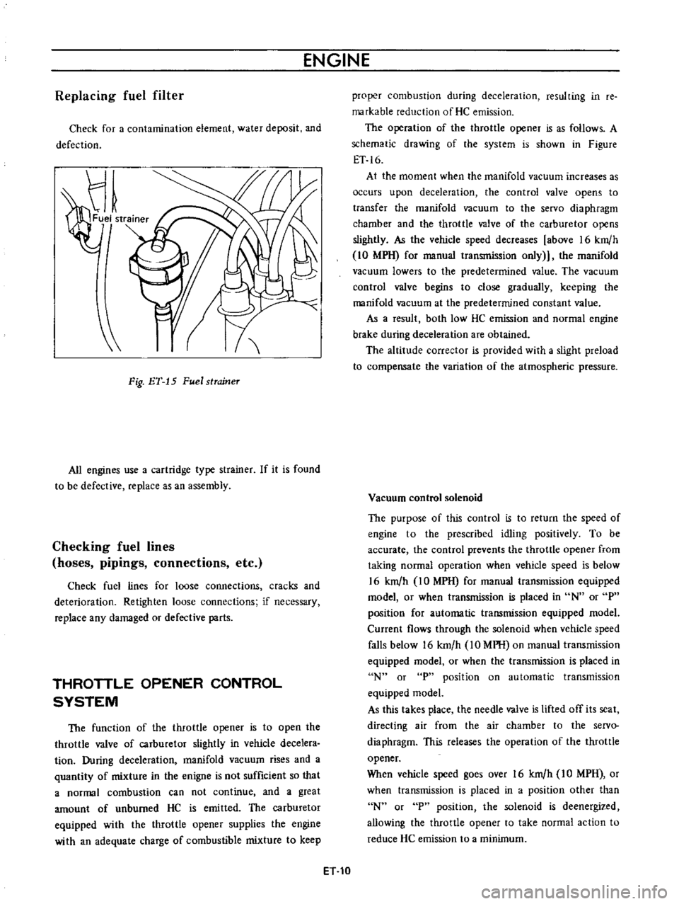
Replacing
fuel
filter
Check
for
a
contamination
element
water
deposit
and
defection
Fig
ET
15
Fuel
strcrineT
All
engines
use
a
cartridge
type
strainer
If
it
is
found
to
be
defective
replace
as
an
assembly
Checking
fuel
lines
hoses
pipings
connections
etc
Check
fuel
lines
for
loose
connections
cracks
and
deterioration
Retighten
loose
connections
if
necessary
replace
any
damaged
or
defective
parts
THROTTLE
OPENER
CONTROL
SYSTEM
The
function
of
the
throttle
opener
is
to
open
the
throttle
valve
of
carburetor
slightly
in
vehicle
decelera
tion
During
deceleration
manifold
vacuum
rises
and
a
quantity
of
mixture
in
the
enigne
is
not
sufficient
so
that
a
normal
combustion
can
not
continue
and
a
great
amount
of
unburned
HC
is
emitted
The
carburetor
equipped
with
the
throttle
opener
supplies
the
engine
with
an
adequate
charge
of
combustible
mixture
to
keep
proper
combustion
during
deceleration
resulting
in
re
markable
reduction
of
He
emission
The
operation
of
the
throttle
opener
is
as
follows
A
schematic
drawing
of
the
system
is
shown
in
Figure
ET
16
At
the
moment
when
the
manifold
vacuum
increases
as
occurs
upon
deceleration
the
control
valve
opens
to
transfer
the
manifold
vacuum
to
the
servo
diaphragm
chamber
and
the
throttle
valve
of
the
carburetor
opens
slightly
As
the
vehicle
speed
decreases
above
16
km
h
10
MPH
for
manual
transmission
only
the
manifold
vacuum
lowers
to
the
predetermined
value
The
vacuum
control
valve
begins
to
close
gradually
keeping
the
manifold
vacuum
at
the
predetermined
constant
value
As
a
result
both
low
HC
emission
and
normal
engine
brake
during
deceleration
are
obtained
The
altitude
corrector
is
provided
with
a
slight
preload
to
compensate
the
variation
of
the
atmospheric
pressure
Vacuum
control
solenoid
The
purpose
of
this
control
is
to
return
the
speed
of
engine
to
the
prescribed
idling
positively
To
be
accurate
the
control
prevents
the
throttle
opener
from
taking
normal
operation
when
vehicle
speed
is
below
16
km
h
IO
MPH
for
manual
transmission
equipped
model
or
when
transmission
is
placed
in
N
or
P
position
for
automatic
transmission
equipped
model
Current
flows
through
the
solenoid
when
vehicle
speed
falls
below
16
km
h
10
MPH
on
manual
transmission
equipped
model
or
when
the
transmission
is
placed
in
N
or
P
position
on
automatic
transmission
equipped
model
As
this
takes
place
the
needle
valve
is
lifted
off
its
seat
directing
air
from
the
air
chamber
to
the
servo
diaphragm
This
releases
the
operation
of
the
throttle
opener
When
vehicle
speed
goes
over
16
km
h
IO
MPH
or
when
transmission
is
placed
in
a
position
other
than
N
or
P
position
the
solenoid
is
deenergized
allowing
the
throttle
opener
to
take
normal
action
to
reduce
He
emission
to
a
minimum
ET
10
Page 325 of 513
ENGINE
Caution
lock
the
front
and
rear
wheels
by
fully
pulling
the
parking
brake
lever
before
con
ducting
this
test
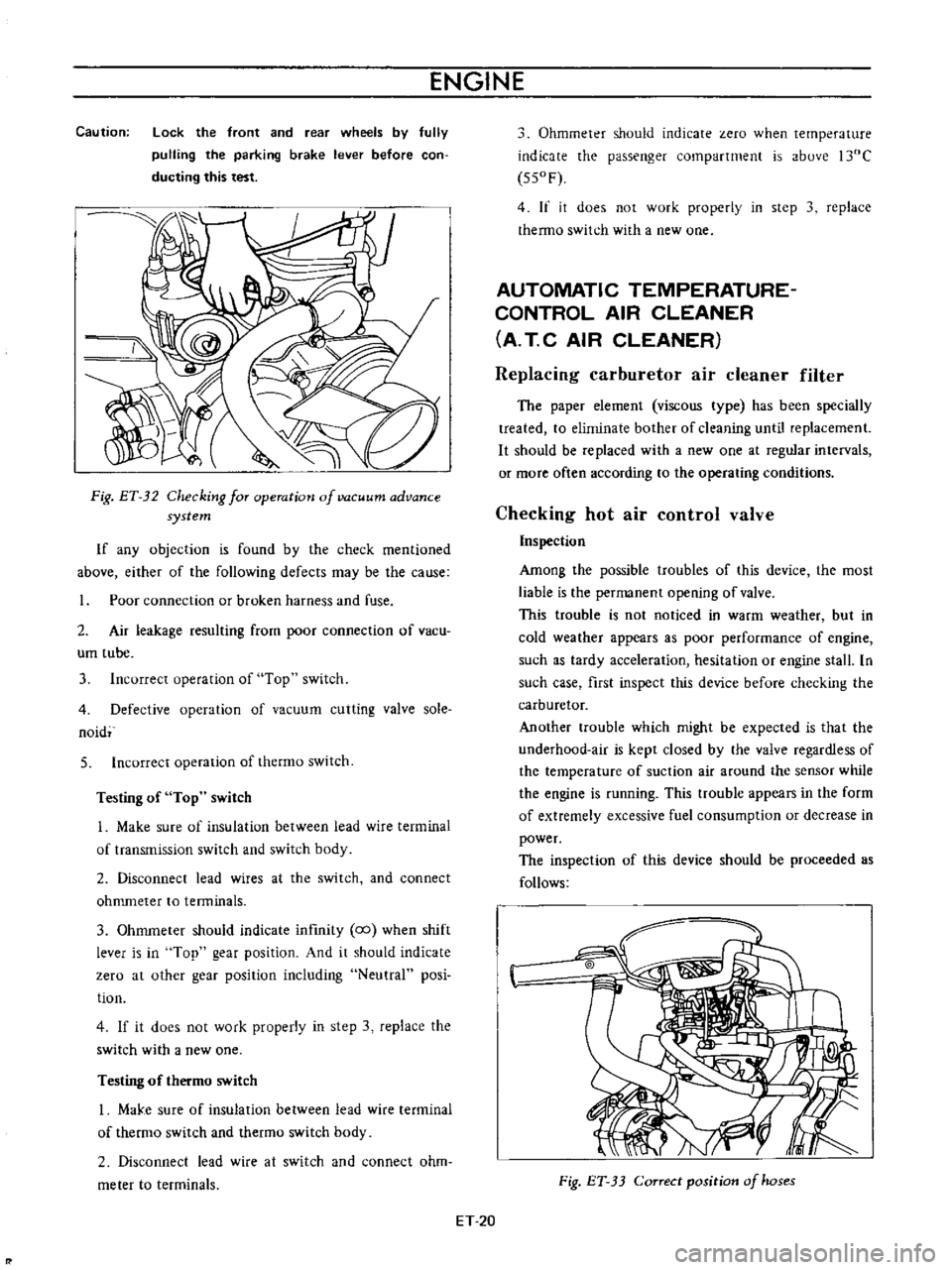
Fig
ET
32
Checking
for
operation
of
vacuum
advance
system
If
any
objection
is
found
by
the
check
mentioned
above
either
of
the
following
defects
may
be
the
cause
Poor
connection
or
broken
harness
and
fuse
2
Air
leakage
resulting
from
poor
connection
of
vacu
um
tube
3
Incorrect
operation
of
Top
switch
4
Defective
operation
of
vacuum
cutting
valve
sole
naid
5
Incorrect
operation
of
thermo
switch
Testing
of
Top
switch
1
Make
sure
of
insulation
between
lead
wire
terminal
of
transmission
switch
and
switch
body
2
Disconnect
lead
wires
at
the
switch
and
connect
ohmmeter
to
tenninals
3
Ohmmeter
should
indicate
infmity
co
when
shift
lever
is
in
Top
gear
position
And
it
should
indicate
zero
at
other
gear
position
including
Neutral
posi
tion
4
If
it
does
not
work
properly
in
step
3
replace
the
switch
with
a
new
one
Testing
of
thermo
switch
I
MaJ
e
sure
of
insulation
between
lead
wire
terminal
of
thermo
switch
and
thetmo
switch
body
2
Disconnect
lead
wire
at
switch
and
connect
ohm
meter
to
terminals
Ohmmeter
should
indicate
zero
when
temperature
indicate
the
passenger
compartment
is
above
l30C
550F
4
If
it
does
not
work
properly
in
step
3
replace
thermo
switch
with
a
new
one
AUTOMATIC
TEMPERATURE
CONTROL
AIR
CLEANER
A
T
C
AIR
CLEANER
Replacing
carburetor
air
cleaner
filter
The
paper
element
viscous
type
has
been
specially
treated
to
eliminate
bother
of
cleaning
until
replacement
It
should
be
replaced
with
a
new
one
at
regular
intervals
or
more
often
according
to
the
operating
conditions
Checking
hot
air
control
valve
Inspection
Among
the
possible
troubles
of
this
device
the
most
liable
is
the
permanent
opening
of
valve
This
trouble
is
not
noticed
in
warm
weather
but
in
cold
weather
appears
as
poor
performance
of
engine
such
as
tardy
acceleration
hesitation
or
engine
stall
In
such
case
first
inspect
this
device
before
checking
the
carburetor
Another
trouble
which
might
be
expected
is
that
the
underhood
air
is
kept
closed
by
the
valve
regardless
of
the
temperature
of
suction
air
around
the
sensor
while
the
engine
is
running
This
ttOuble
appears
in
the
form
of
extremely
excessive
fuel
consumption
or
decrease
in
power
The
inspection
of
this
device
should
be
proceeded
as
follows
Fig
ET
33
Correct
position
of
hoses
ET
20
Page 328 of 513
EMISSION
CONTROL
AND
TUNE
UP
CD
@
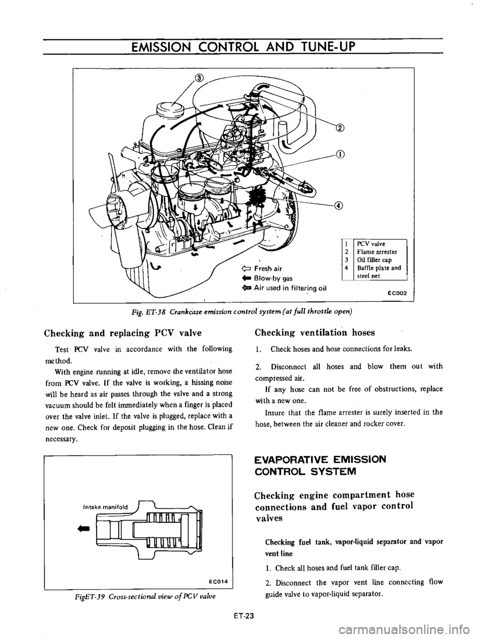
Fresh
air
Blow
by
gas
Air
used
in
filtering
oil
1
PCV
valve
2
Flame
arrester
3
Oil
filler
cap
4
Baffle
plate
and
steel
net
E
C002
Fig
ET
J8
Crankcase
emission
control
system
at
full
throttle
open
Checking
and
replacing
PCV
valve
Test
PCV
valve
in
accordance
with
the
following
me
thod
With
engine
running
at
idle
remove
the
ventilator
hose
from
PCV
valve
If
the
valve
is
working
a
hissing
noise
will
be
heard
as
air
passes
through
the
valve
and
a
strong
vacuum
should
be
felt
immediately
when
a
finger
is
placed
over
the
valve
inlet
If
the
valve
is
plugged
replace
with
a
new
one
Check
for
deposit
plugging
in
the
hose
Clean
if
necessary
Intake
manifold
l
illlr
nnnl
UUUU
l
I
G
EC014
FigET
39
Cross
sectional
view
of
PCV
valve
Checking
ventilation
hoses
I
Check
hoses
and
hose
connections
for
leaks
2
Disconnect
all
hoses
and
blow
them
out
with
compressed
air
If
any
hose
can
not
be
free
of
obstructions
replace
with
a
new
one
Insure
that
the
flame
arrester
is
surely
inserted
in
the
hose
between
the
air
cleaner
and
rocker
cover
EVAPORATIVE
EMISSION
CONTROL
SYSTEM
Checking
engine
compartment
hose
connections
and
fuel
vapor
control
valves
Checking
fuel
tank
vapor
liquid
separator
and
vapor
vent
line
I
Check
all
hoses
and
fuel
tank
ftIler
cap
2
Disconnect
the
vapor
vent
line
connecting
flow
guide
valve
to
vapor
liquid
separator
ET
23
Page 337 of 513
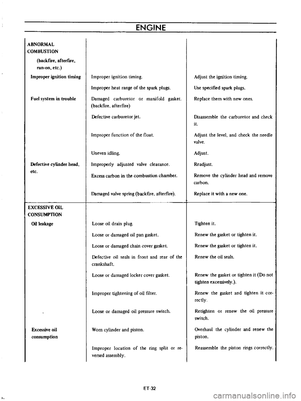
ABNORMAL
COMBUSTION
backfire
afterflfe
run
on
etc
Improper
ignition
timing
Fuel
system
in
trouble
Defective
cylinder
head
etc
EXCESSIVE
OIL
CONSUMPTION
Oil
leakage
Excessive
oil
consumption
ENGINE
Improper
ignition
timing
Improper
heat
range
of
the
spark
plugs
Damaged
carburetor
or
manifold
gasket
backfire
afterflre
Defective
carburetor
jet
Improper
function
of
the
float
Uneven
idling
Improperly
adjusted
valve
clearance
Excess
carbon
in
the
combustion
chamber
Damaged
valve
spring
backfire
afterure
Loose
oil
drain
plug
Loose
or
damaged
oil
pan
gasket
Loose
or
damaged
chain
cover
gasket
Defective
oil
seals
in
front
and
rear
of
the
crankshaft
Loose
or
damaged
locker
cover
gasket
Improper
tightening
of
oil
filter
Loose
or
damaged
oil
pressure
switch
Worn
cylinder
and
piston
Improper
location
of
the
ring
split
or
reo
versed
assembly
ET
32
Adjust
the
ignition
timing
Use
specified
spark
plugs
Replace
them
with
new
ones
Disassemble
the
carburetor
and
check
it
Adjust
the
level
and
check
the
needle
valve
Adjust
Readjust
Remove
the
cylinder
head
and
remove
carbon
Replace
it
with
a
new
one
Tighten
it
Renew
the
gasket
or
tighten
it
Renew
the
gasket
or
tighten
it
Renew
the
oil
seals
Renew
the
gasket
or
tighten
it
Do
not
tighten
excessively
Renew
the
gasket
and
tighten
it
cor
rectly
Retighten
or
renew
the
oil
pressure
switch
Overhaul
the
cylinder
and
renew
the
piston
Reassemble
the
piston
rings
correctly
Page 372 of 513
ENGINE
27
Install
the
oil
pump
with
oil
filter
28
Install
the
alternator
fan
and
fan
belt
29
Install
the
fuel
pump
30
Install
the
distributor
assembly
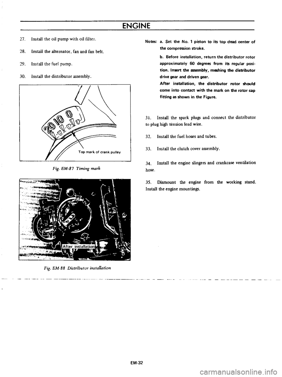
Fig
EM
B7
Timing
maTk
Fig
EM
SS
Distributor
installation
EM
32
Notes
3
Set
the
No
1
piston
to
its
top
dead
center
of
the
compression
stroke
b
Before
installation
return
the
distributor
rotor
approximately
60
degrees
from
its
regular
posi
tion
Insert
the
assembly
meshing
the
distributor
drive
gear
and
driven
gear
After
installation
the
distributor
rotor
should
come
into
contact
with
the
mark
on
the
rotor
cap
fitting
as
shown
in
the
Figure
31
Install
the
spark
plugs
and
connect
the
distributor
to
plug
high
tension
lead
wire
32
Install
the
fuel
hoses
and
tubes
33
Install
the
clutch
cover
assembly
34
Install
the
engine
stingers
and
crankcase
ventilation
hose
35
Dismount
the
engine
from
the
working
stand
Install
the
engine
mountings
Page 379 of 513
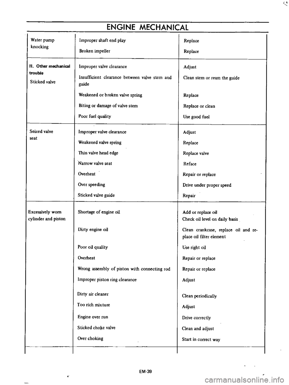
Water
pump
knocking
II
Other
mechanical
trouble
Sticked
valve
Seized
valve
seat
Excessively
worn
cylinder
and
piston
ENGINE
MECHANICAL
Improper
shaft
end
play
Broken
impeller
Improper
valve
clearance
Insufficient
clearance
between
valve
stem
and
guide
Weakened
or
broken
valve
spring
Biting
or
damage
ofvalve
stem
Poor
fuel
quality
Improper
valve
clearance
Weakened
valve
spring
Thin
valve
head
edge
Narrow
valve
seat
Overheat
Over
speeding
Sticked
valve
guide
Shortage
of
engine
oil
Dirty
engine
oil
Poor
oil
quality
Overheat
Wrong
assembly
of
piston
with
connecting
rod
Improper
piston
ring
clearance
Dirty
air
cleaner
Too
rich
mixture
Engine
over
run
Slicked
cho
e
valve
Over
choking
EM
39
Replace
Replace
Adjust
Clean
stem
or
ream
the
guide
Replace
Replace
or
clean
Use
good
fuel
Adjust
Replace
Replace
valve
Reface
Repair
or
replace
Drive
under
proper
speed
Repair
Add
or
replace
oil
Check
oil
level
on
daily
basis
Clean
crankcase
replace
oil
and
re
place
oil
fIlter
element
use
right
oil
Repair
or
replace
Repair
or
replace
Adjust
Clean
periodically
Adjust
Drive
correctly
Clean
and
adjust
Start
in
correct
way
Page 401 of 513
ENGINE
6
f
I
Filter
to
Primary
main
nozzk
18
Secondary
throttle
valve
2
Needle
valve
11
Primary
main
air
bleed
19
Primal
throttle
valve
3
Secondary
slow
jet
12
Primary
slow
air
bleed
20
Idle
nozzle
4
Secondary
slow
air
bleed
13
Primary
slow
jet
2t
By
pass
hole
5
Secondary
main
air
bleed
14
Float
22
Primary
main
jet
6
Secondary
main
nozzle
15
Secondary
emulsion
tube
23
Primary
emulsion
tube
7
Secondary
air
vent
pipe
t6
Secondary
main
jet
24
Power
valve
8
Choke
valve
t7
Auxiliary
alve
25
Level
gauge
9
Primary
air
nt
pipe
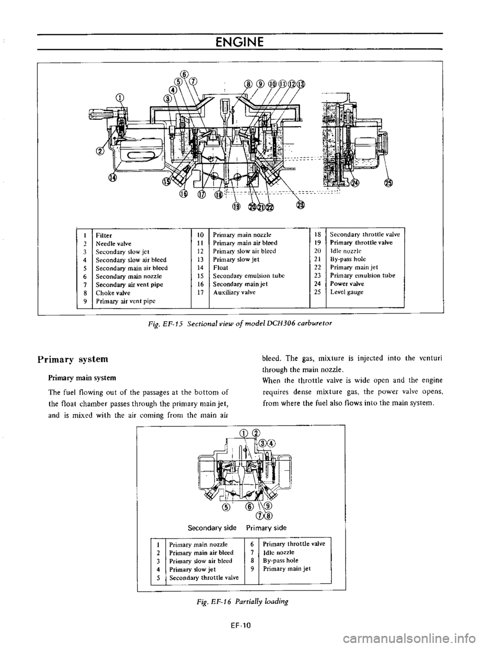
Fig
EF
15
Sectional
view
of
model
DCH306
carburetor
bleed
The
gas
mixture
is
injected
into
the
venturi
through
the
main
nozzle
When
the
throttle
valve
is
wide
open
and
the
engine
requires
dense
mixture
gas
the
power
valve
opens
from
where
the
fuel
also
flows
into
the
main
system
Primary
system
Primary
main
system
The
fuel
flowing
out
of
the
passages
at
the
bottom
of
the
float
chamber
passes
through
the
primary
main
jet
and
is
mixed
with
the
air
coming
from
the
main
air
Secondary
side
Primary
side
1
Primary
main
nozzle
2
Primary
main
air
bleed
3
Primary
slow
air
bleed
4
Primary
slow
jet
5
Secondary
throttle
valve
6
Primary
throttle
valve
7
Idle
nozzle
8
By
pass
hole
9
Primary
main
jet
Fig
EF
16
PaTtially
loading
EF
10
Page 403 of 513
ENGINE
Step
system
The
construction
of
this
system
corresponds
to
the
idling
and
slow
system
of
the
primary
system
This
system
aims
at
the
power
filling
up
of
the
gap
when
fuel
supply
is
transferred
from
the
primary
system
to
the
secondary
system
The
step
port
is
located
near
the
auxiliary
valve
in
its
fully
closed
state
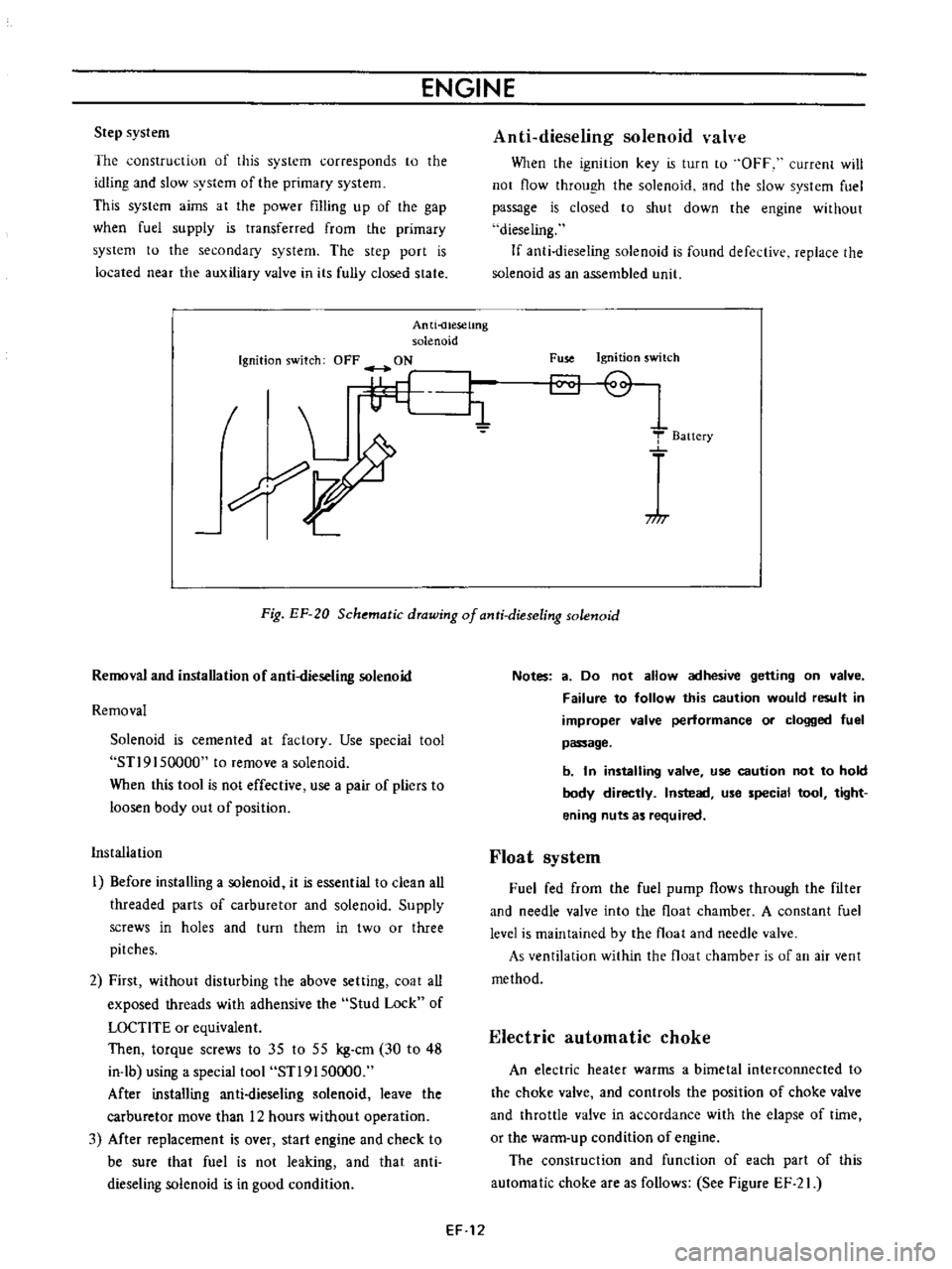
Anti
uesetmg
solenoid
Ignition
switch
OFF
ON
I
L
i1
7
I
Anti
dieseling
solenoid
valve
When
the
ignition
key
is
turn
to
OFF
current
will
not
flow
through
the
solenoid
and
the
slow
system
fuel
passage
is
closed
to
shut
down
the
engine
without
dieseling
If
anti
dieseling
solenoid
is
found
defective
replace
the
solenoid
as
an
assembled
llnit
Fuse
Ignition
switch
T
Baitery
717
Fig
EF
20
Schematic
drawing
of
anti
dieseling
solenoid
Removal
and
installation
of
anti
dieseling
solenoid
Removal
Solenoid
is
cemented
at
factory
Use
special
tool
STl9
I
50000
to
remove
a
solenoid
When
this
tool
is
not
effective
use
a
pair
of
pliers
to
loosen
body
out
of
position
Installation
I
Before
installing
a
solenoid
it
is
essential
to
clean
all
threaded
parts
of
carburetor
and
solenoid
Supply
screws
in
holes
and
turn
them
in
two
or
three
pitches
2
First
without
disturbing
the
above
setting
coat
all
exposed
threads
with
adhensive
the
Stud
Lock
of
LOCTlTE
or
equivalent
Then
torque
screws
to
35
to
55
kg
cm
30
to
48
in
lb
using
a
special
tool
STl9150000
After
installing
anti
dieseling
solenoid
leave
the
carburetor
move
than
12
hours
without
operation
3
Mter
replacement
is
over
start
engine
and
check
to
be
sure
that
fuel
is
not
leaking
and
that
anti
dieseling
solenoid
is
in
good
condition
Notes
a
Do
not
allow
adhesive
getting
on
valve
Failure
to
follow
this
caution
would
result
in
improper
valve
performance
or
clogged
fuel
passage
b
In
installing
valve
use
caution
not
to
hold
body
directly
Instead
use
special
tool
tight
ening
nuts
as
required
Float
system
Fuel
fed
from
the
fuel
pump
flows
through
the
filter
and
needle
valve
into
the
float
chamber
A
constant
fuel
level
is
maintained
by
the
float
and
needle
valve
As
ventilation
within
the
float
chamber
is
of
an
air
vent
method
Electric
automatic
choke
An
electric
heater
warms
a
bimetal
interconnected
to
the
choke
valve
and
controls
the
position
of
choke
valve
and
throttle
valve
in
accordance
with
the
elapse
of
time
or
the
warm
up
condition
of
engine
The
construction
and
function
of
each
part
of
this
automatic
choke
are
as
follows
See
Figure
EF
21
EF
12