engine oil DATSUN PICK-UP 1977 Service Manual
[x] Cancel search | Manufacturer: DATSUN, Model Year: 1977, Model line: PICK-UP, Model: DATSUN PICK-UP 1977Pages: 537, PDF Size: 35.48 MB
Page 506 of 537

Notes
a
The
bubbles
seen
through
the
sight
glass
are
influenced
by
the
ambient
temperature
Since
the
bubbles
are
hard
to
show
up
in
comparatively
low
temperatures
below
200C
6S0
F
it
is
possible
that
a
slightly
larger
amount
of
refrigerant
would
be
filled
if
supplied
according
to
the
sight
glass
Be
sure
to
recheck
the
amount
when
it
exceeds
200C
680F
In
higher
temperature
the
bubbles
are
easy
to
show
up
b
When
the
screen
in
the
receiver
dryer
is
clogged
the
bubbles
will
appear
even
if
the
amount
of
refrig
erant
is
normal
In
this
case
the
outlet
side
pipe
of
the
receiver
dryer
becomes
considerably
cold
PERFORMANCE
TEST
Check
for
the
amount
of
refrigerant
in
the
system
can
be
made
by
meas
uring
pressure
on
discharge
side
The
correct
amount
of
refrigerant
is
in
the
system
if
pressure
on
the
discharge
side
is
within
the
specified
range
For
details
refer
to
Perform
ance
Test
described
later
Overcharging
will
show
up
in
higher
pressure
on
discharge
side
COMPRESSOR
OIL
LEVEL
CHECK
The
oil
used
to
lubricate
compres
sor
circulates
into
system
from
the
oil
sump
while
c9mpressor
is
operating
The
efore
to
correctly
measure
com
pressor
oil
the
amount
of
oil
flowing
to
system
must
be
considered
If
a
considerable
amount
of
leakage
of
refrigerant
gas
happens
the
leakage
of
compressor
oil
is
also
considered
There
will
be
no
compressor
oil
leak
age
from
a
completely
sealed
system
When
system
operates
under
satisfying
condition
the
compressor
oil
level
check
is
unnecessary
When
checking
the
level
of
com
pressor
oil
or
when
replacing
any
component
part
of
the
system
use
the
following
service
procedure
This
fa
cilitates
to
return
oil
to
compressor
I
Operate
compressor
at
engine
idling
speed
1
000
rpm
or
below
with
controls
set
for
maximum
cooling
Air
Conditionin
j
and
high
blower
speed
for
10
to
15
minutes
in
order
to
return
compressor
oil
to
compressor
2
Stop
the
engine
and
discharge
refrigerant
of
system
and
then
remove
compressor
from
the
vehicle
3
Remove
compressor
fIller
plug
Drain
compressor
oil
from
compres
sor
oil
sump
and
measure
the
amount
4
Compressor
oil
is
satisfactory
if
the
following
amount
of
oil
remains
in
the
compressor
Residual
oil
S5
to
128
gr
3
to
4
oz
5
Check
the
cleanliness
of
the
oil
If
the
oil
contains
chips
or
other
foreign
material
clean
oil
5ump
with
new
oil
6
Discard
the
used
oil
and
fili
with
the
same
amount
of
new
oil
Add
oil
if
found
less
than
above
amount
Fig
AC
27
Filler
plug
If
compressor
is
inoperative
due
to
faulty
compressor
or
heavy
loss
of
refrigerant
remove
compressor
and
repair
as
necessary
Then
pour
oil
up
to
correct
level
and
install
on
engine
After
above
steps
have
been
complet
ed
recheck
oil
level
drain
oil
to
correct
level
if
level
is
excessively
high
PERFORMANCE
TEST
The
cooling
performance
of
the
air
conditioner
changes
considerably
with
changes
in
surrounding
conditions
Testing
must
be
performed
using
the
correct
method
This
test
is
used
to
judge
whether
system
is
operating
cor
rectly
and
can
also
be
used
as
a
guide
in
checking
for
problems
I
Park
the
vehicle
indoors
or
in
the
shade
AC
17
2
Open
all
the
windows
of
the
vehicle
fully
However
close
the
doors
3
Open
the
hood
4
Connect
manifold
gauge
to
high
and
low
side
service
valves
of
the
system
Refer
to
Handling
Manifold
Ga
uge
5
Set
fan
control
lever
to
maxi
mum
6
Set
temperature
control
lever
to
max
cool
position
7
Start
the
engine
and
hold
engine
speed
at
1
500
rpm
S
After
the
air
conditioner
has
been
operated
for
about
10
minutes
measure
system
pressures
at
high
pres
sure
discharge
side
and
low
pressure
suction
side
9
Measure
the
temperature
of
dis
charge
air
at
outlet
grille
10
Measure
the
temperature
of
capin
11
Measure
ambient
temperature
and
humidity
one
meter
3
3
ft
away
from
condenser
front
Be
careful
not
to
expose
dry
buib
and
wet
bulb
to
direct
sunlight
12
Check
for
any
abnormalities
by
comparing
the
test
results
with
stand
ard
pressure
in
Performance
Chart
Notes
a
The
pressure
will
change
in
the
followi
g
manner
with
changes
in
conditions
When
blower
speed
is
low
dis
charge
pressure
will
drop
When
the
relative
humidity
of
in
take
air
is
low
discharge
pressure
will
drop
b
The
temperature
will
change
in
the
following
manner
with
changes
in
conditions
When
the
ambient
air
temperature
is
low
the
outlet
air
temperature
will
become
low
If
the
test
reveals
that
there
is
any
abnormality
in
system
pressure
isolate
the
cause
and
repair
by
reference
to
the
Trouble
Diagnoses
and
Cor
rections
Page 510 of 537

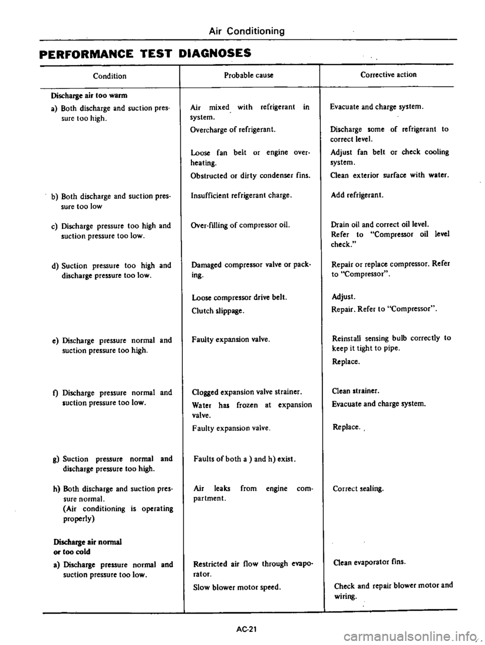
Air
Conditioning
PERFORMANCE
TEST
DIAGNOSES
Condition
Discharge
air
too
warm
a
Both
discharge
and
suction
pres
sure
too
high
b
Both
discharge
and
suction
pres
sure
too
low
c
Discharge
pressure
too
high
and
suction
pressure
too
low
d
Suction
pressure
too
high
and
discharge
pressure
too
low
e
Discharge
pressure
normal
and
suction
pressure
too
high
t
Discharge
pressure
normal
and
luction
pressure
too
low
g
Suction
pressure
normal
and
discharge
pressure
too
high
h
Both
discharge
and
suction
pres
sure
normal
Air
conditioning
is
operating
properly
Discharge
air
normal
or
too
cold
a
Discharge
pressure
normal
and
suction
pressure
too
low
Probable
cause
Air
mixed
with
refrigerant
in
system
Overcharge
of
refrigerant
Loose
fan
belt
or
engine
over
heating
Obstructed
or
dirty
condenser
fins
Insufficient
refrigerant
charge
Over
filling
of
compressor
oil
Damaged
compressor
valve
or
pack
ing
Loose
compressor
drive
belt
Clutch
slippage
Faulty
expansion
valve
Clogged
expansion
valve
strainer
Water
has
frozen
at
expansion
valve
Faulty
expansion
valve
Faults
of
both
a
and
h
exist
Air
leaks
from
engine
com
partment
Restricted
air
flow
through
evapo
ratof
Slow
blower
motor
speed
AC
21
Corrective
action
Evacuate
and
charge
system
Discharge
some
of
refrigerant
to
correct
level
Adjust
fan
belt
or
check
cooling
system
Clean
exterior
surface
with
water
Add
refrigerant
Drain
oil
and
correct
oil
level
Refer
to
Compressor
oil
level
check
Repair
or
replace
compressor
Refer
to
Compressor
Adjust
Repair
Refer
to
Compressor
Reinstall
sensing
bulb
correctly
to
keep
it
tight
to
pipe
Replace
Clean
strainer
Evacuate
and
charge
system
Replace
Correct
sealing
Clean
evaporator
fins
Check
and
repair
blower
motor
and
wiring
Page 515 of 537

2
R
C7
c
L
PJJ
I
8
INSTALLATION
a
c
J
l
i
rp
To
install
compressor
reverse
the
order
of
removal
Observe
the
follow
ing
nhlJo
e
trorf
1001
vom
R
i
n3
Wheliqli
liiAniitg
fiil
l
in
pt
l
witlil
tiiel
sam
efuouiitITof
b11
1fasitlult
used
previously
v
d
rnl
2
Oil
capacity
new
compressor
O
910
1
owt
llllt
blj
f
H
w
s
013
5
rlT
s
0
111
boc
19
bB1rllo
bi2
qqll
no
e
l
bffik
kuanM
mpdi
x
of
Jli
oln
L
il
m
1IlffiiOrb
fler
ot
oldm
F
n
Cheo
f
undeF
r
n
al
1
aQ
r1tIU
Jt
t31
HClJI1
t
JIVU
i
rlUI
1o
ifm
ft
q
t
VI
31U
S
ltlod
bnM
UfO
l
W
kldf
CJiJi
ti
WIf
nl
L
llil
g
ncn
d
oressor
M
et
illpuntinl
botts
if
l9Wul
fb
i
l
fI
I
l
1Ttio
l
qqlJ
necessary
re
Ighten
I
d
210
Air
Conditioning
Tightening
torque
Flexible
hose
to
compressor
dl
t
kg
J
l
IQ
1
Tf
es
oriti
ra
Lbolts
IbP
fo
o15g
m
J
r
f6i
o
20
i
il
f
J
rt
I
r
aGket
engine
Dons
1
1
0
1
1
3
16
5
l11fd
1l
V
f
42
3
3U
llif
Yl
I
u
y
j
3
D
not
remove
IJgs
orflexibie
1i6
e
before
ready
for
immediate
use
4l
di
Wheniiinstallingccomptess
i
turn
it
serWfiPtiffies
SlOt
5
When
connecting
flexible
hose
to
9mPr
ssor
apD
v
a
coat
of
Hfresh
JU
UI
l1Il
t
2
JIUU
uOHltl
r
fl
compressor
0
1
to
fs
aHn
lurfaces
of
1n
1l11
JJ
J
f
PJU
Ht
UlUJ
jJ
joints
AC
26
5
1
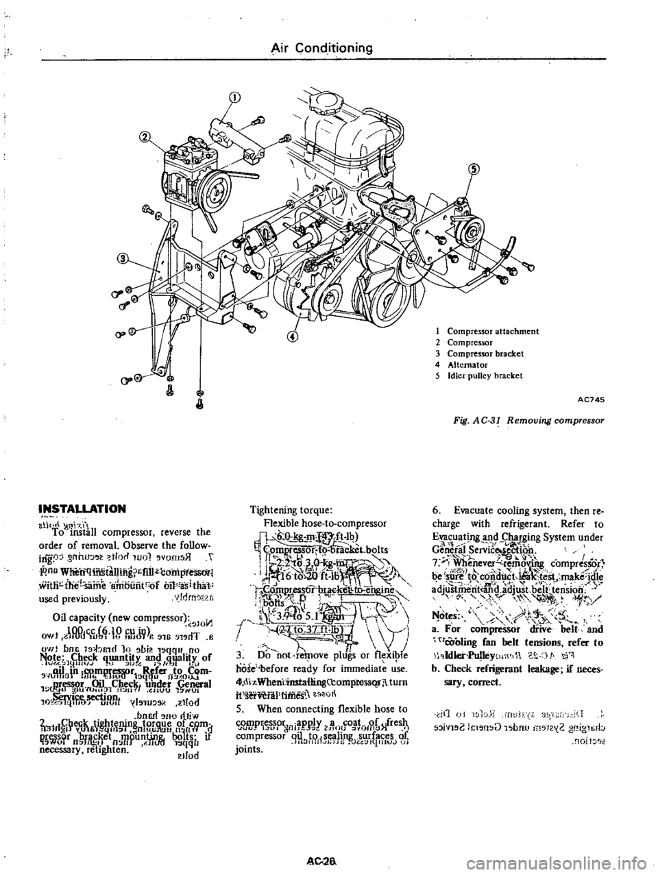
Compressor
attachment
2
Compressor
3
Compressor
bracket
4
AHernator
5
Idler
pulley
bracket
AC745
Fig
AC
31
Removing
compressor
6
Evacuate
cooling
system
then
re
charge
with
refrigerant
Refer
to
Evacuating
and
Charging
System
under
l
r
Gen
efal
Servic
ectioo
f
iI
t
7
F
Whenever
remoV
J
compres
r
be
su
J
t8
C6itiu
t
Ua
t
st
make
idie
mV
i
1rJ
adjustril
rit
and
adjwt
beJf
tension
yv
1
r
Y
N
o
s
9
r
h
v
a
For
compressor
diive
belt
and
tOoling
fan
belt
tensions
refer
to
1
Ildlet
Yt
j
WI
c
S
t
q
b
Cheok
refrigerant
leakage
if
neces
sary
correct
dO
I
wl
Tw
l
rt
f
r2
iVl
2
i
l
n
U
l
bnu
1
1Z
2
gf
ign
rb
nojJ
2
Page 518 of 537

INSPECTION
Evaporator
Check
evaporator
for
leakage
or
damage
If
damaged
replace
Expansion
valve
Check
expansion
valve
for
leakage
or
clogging
If
clogged
clean
filter
in
expansion
valve
If
damaged
replace
RECEIVER
DRYER
AND
PIPING
REMOVAL
AND
INSTAUATION
Receiver
dryer
I
Disconnect
battery
ground
cable
2
Discharge
system
Refer
to
Dis
charging
System
under
General
Service
section
3
Disconnect
compressor
lead
wire
at
connector
4
Disconnect
cooling
pipes
at
joints
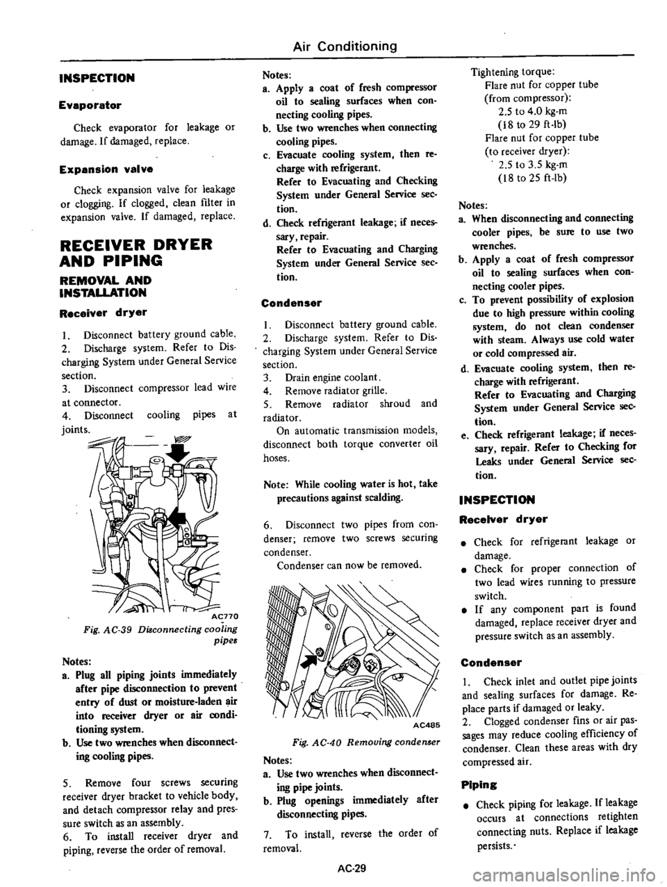
Acno
Fig
AC
39
Diaconnecting
coo
ing
pipes
Notes
a
Plug
all
piping
joints
immediately
after
pipe
disconnection
to
prevent
entry
of
dust
or
moisture
laden
air
into
receiver
dryer
or
air
aJOdi
tioning
system
b
Use
two
wrenches
when
dIsconnect
ing
cooling
pipes
5
Remove
four
screws
securing
receiver
dryer
bracket
to
vehicle
body
and
detach
compressor
relay
and
pres
sure
switch
as
an
assembly
6
To
install
receiver
dryer
and
piping
reverse
the
order
of
removal
Air
Conditioning
Notes
a
Apply
a
coat
of
fresh
compressor
oil
to
sealing
surfaces
when
con
necting
cooling
pipes
b
Use
two
wrenches
when
connecting
cooling
pipes
c
Evacuate
cooling
system
then
re
charge
with
refrigerant
Refer
to
Evacuating
and
Checking
System
under
General
Service
sec
tion
d
Check
refrigerant
leakage
if
neces
sary
repair
Refer
to
Evacuating
and
Charging
System
under
General
Service
See
tion
Condenser
Disconnect
battery
ground
cable
2
Discharge
system
Refer
to
Dis
charging
System
under
General
Service
section
3
Drain
engine
coolant
4
Remove
radiator
grille
5
Remove
radiator
shroud
and
radiator
On
automatic
transmission
models
disconnect
both
torque
converter
oil
hoses
Note
While
cooling
water
is
hot
take
precautions
against
scalding
6
Disconnect
two
pipes
from
con
denser
remove
two
screws
securing
condenser
Condenser
can
now
be
removed
AC485
Fig
AC
40
Removing
conden
er
Notes
a
Use
two
wrenches
when
disconnect
ing
pipe
joints
b
Plug
openings
immediately
after
disconnecting
pipes
7
To
install
reverse
the
order
of
removal
AC
29
Tightening
torque
Flare
nut
for
copper
tube
from
compressor
2
5
to
4
0
kg
m
i8
to
29
ft
Ib
Flare
nut
for
copper
tube
to
receiver
dryer
2
5
to
3
5
kg
m
i8
to
25
ft
lb
Notes
a
When
disconnecting
and
connecting
cooler
pipes
be
sure
to
use
two
wrenches
b
Apply
a
coat
of
fresh
compressor
oil
to
sealing
surfaces
when
con
necting
cooler
pipes
c
To
prevent
possibility
of
explosion
due
to
high
pressure
within
cooling
system
do
not
clean
condenser
with
steam
Always
use
cold
water
or
cold
compressed
air
d
Evacuate
cooling
system
then
re
charge
with
refrigerant
Refer
to
Evacuating
and
Charging
System
under
General
Service
sec
tion
e
Check
refrigerant
leakage
if
neces
sary
repair
Refer
to
Checking
for
Leaks
under
General
Service
sec
tion
INSPECTION
RecelYer
dryer
Check
for
refrigerant
leakage
or
damage
Check
for
proper
connection
of
two
lead
wires
running
to
pressure
switch
If
any
component
part
is
found
damaged
replace
receiver
dryer
and
pressure
switch
as
an
assembly
Condenser
I
Check
inlet
and
outlet
pipe
joints
and
sealing
surfaces
for
damage
Re
place
parts
if
damaged
or
leaky
2
Clogged
condenser
fins
or
air
pas
sages
may
reduce
cooling
efficiency
of
condenser
Clean
these
areas
with
dry
compressed
air
Piping
Check
piping
for
leakage
If
leakage
occurs
at
connections
retighten
connecting
nuts
Replace
if
leakage
persists
Page 532 of 537

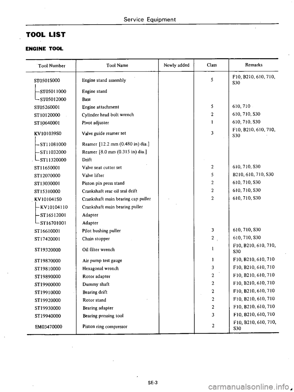
Service
Equipment
TOOL
LIST
ENGINE
TOOL
Tool
Number
Tool
Name
Newly
added
Class
Remarks
ST050
I
SODa
Engine
stand
assembly
5
FIO
B2iO
610
710
S30
tST05011000
Engine
stand
ST050
I
2000
Base
ST05260001
Engine
attachment
5
610
710
STlOl20000
Cylinder
head
bolt
wrench
2
610
710
S30
STl
0640001
Pivot
adjuster
I
610
710
S30
KVIOI039S0
Valve
guide
reamer
set
3
FiO
B210
610
710
S30
STl1081
000
Reamer
12
2
mffi
0
480
in
dia
J
STl1032000
Reamer
8
0
mffi
0
315
in
dia
STl1320000
Drift
STll650001
Valve
seat
cutter
set
2
610
710
S30
STl2070000
Valve
lifter
5
B210
610
710
S30
STl3030001
Piston
pin
press
stand
2
610
710
S30
STl53
10000
Crankshaft
rear
oil
seal
drift
2
610
710
S30
KVI01041S0
Crankshaft
main
bearing
cap
puller
2
610
710
S30
KVIOI04110
Crankshaft
main
bearing
puller
STl6512001
Adapter
STl6701001
Adapter
STl6610001
Pilot
bushing
puller
3
610
710
S30
STl7420001
Chain
stopper
2
610
710
S30
STl9320000
Oil
filter
wrench
FIO
B210
610
710
S30
STl9870000
Air
pump
test
gauge
FI0
B210
610
710
STl98
10000
Hexagonal
wrench
3
FIO
B2iO
610
710
STl9890000
Rotor
adapter
2
FIO
B210
610
710
STl9900000
Dummy
shaft
2
FIO
B210
610
710
STl99
10000
Bearing
drift
2
FIO
B210
610
710
STl9920000
Rotor
stand
2
FIO
B210
610
710
STl9930000
Bearing
adapter
2
FIO
B210
610
710
ST
I
9940000
Bearing
pressing
tool
3
FIO
B210
610
710
EM03470000
Piston
ring
compressor
2
FIO
B210
610
710
S30
SE
3