engine oil DATSUN PICK-UP 1977 Service Manual
[x] Cancel search | Manufacturer: DATSUN, Model Year: 1977, Model line: PICK-UP, Model: DATSUN PICK-UP 1977Pages: 537, PDF Size: 35.48 MB
Page 451 of 537
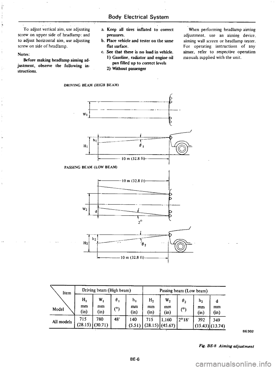
To
adjust
vertical
aim
use
adjusting
screw
on
upper
side
of
headlamp
and
to
adjust
horizontal
aim
use
adjusting
screw
on
side
of
head
lamp
Notes
Before
making
headlarnp
aiming
ad
justment
observe
the
foUowing
in
structions
Body
Electrical
System
a
Keep
aU
tires
inflated
to
correct
pressures
b
Place
vehicle
and
tester
on
the
same
flat
surface
c
See
that
there
is
no
load
in
vehicle
I
Gasoline
radiator
and
engine
oil
pan
filled
up
to
correct
levels
2
Without
passenger
When
performing
headlamp
aiming
adjustment
use
an
aiming
device
aiming
wall
screen
or
headlamp
tester
For
operating
instructions
of
any
aimer
refer
to
respective
operation
manuals
supplied
with
the
unit
DRIVING
BEAM
HIGH
BEAM
L
wt
H
G
hi
i
iiI
PASSING
BEAM
LOW
BEAM
10
m
32
8
ft
W2
H2
10
m
02
8
n
d
20
h2
I
02
I
I
f
10
m
32
8
ft
Driving
beam
High
beam
Passing
beam
Low
beam
HI
WI
01
mm
mm
CO
in
in
I
715
780
48
All
models
28
15
30
71
hI
H2
W2
h2
O2
d
mm
mm
mm
in
in
in
0
140
I
715
11
160
12018
5
51
28
15
45
67
mm
mm
in
in
392
349
is
43
13
74
BE302
Fig
BE
8
Aiming
adjustment
BE
6
Page 461 of 537
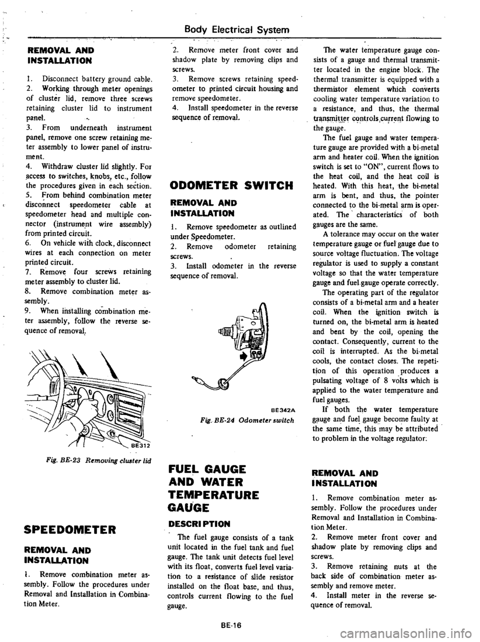
REMOVAL
AND
INSTALLATION
I
Disconnect
battery
ground
cable
2
Working
through
meter
openings
of
cluster
lid
remove
three
screws
retaining
cluster
lid
to
instrument
panel
3
From
underneath
instrument
panel
remove
one
screw
retaining
me
ter
assembly
to
lower
panel
of
instru
ment
4
Withdraw
cluster
lid
slightly
For
ccess
to
switches
knobs
etc
follow
the
procedures
given
in
each
section
5
From
behind
combination
meter
disconnect
speedometer
cable
at
speedometer
head
and
multiple
con
nector
instrume
nt
wire
assembly
from
printed
circuit
6
On
vehicle
with
clock
disconnect
wires
at
each
connection
on
meter
printed
circuit
7
Remove
four
screws
retaining
me
ter
assembly
to
cluster
lid
8
Remov
combination
meter
as
sembly
9
When
installing
combination
me
ter
assembly
follow
the
reverse
se
quence
of
removal
Fig
BE
23
Removing
eluster
lid
SPEEDOMETER
REMOVAL
AND
INSTALLATION
1
Remove
combination
meter
as
sembly
Follow
the
procedures
under
Removal
and
Installation
in
Combina
tion
Meter
Body
Electrical
System
2
Remove
meter
front
cover
and
shadow
plate
by
removing
clips
and
screws
3
Remove
screws
retaining
speed
ometer
to
printed
circuit
housing
and
remove
speedometer
4
Install
speedometer
in
the
reverse
sequence
of
removal
ODOMETER
SWITCH
REMOVAL
AND
INSTALLATION
I
Remove
speedometer
as
outlined
under
Speedometer
2
Remove
odometer
retaining
screws
3
Install
odometer
in
the
reverse
sequence
of
removal
BE342A
Fig
BE
24
Odometerswitch
FUEL
GAUGE
AND
WATER
TEMPERATURE
GAUGE
DESCRI
PTION
The
fuel
gauge
consists
of
a
tank
unit
located
in
the
fuel
tank
and
fuel
gauge
The
tank
unit
detects
fuel
level
with
its
float
converts
fuel
level
varia
tion
to
a
resistance
of
slide
resistor
installed
on
the
float
base
and
thus
controls
current
flowing
to
the
fuel
gauge
BE16
The
water
temperature
gauge
con
sists
of
a
gauge
and
thermal
transmit
ter
located
in
the
engine
block
The
thermal
transmitter
is
equipped
with
a
thermistor
element
which
converts
cooling
water
temperature
variation
to
a
resistance
and
thus
the
thermal
tr
t
c
rtrols
cUfTent
flowing
to
the
gauge
The
fuel
gauge
and
water
tempera
ture
gauge
are
provided
with
a
bi
metal
arm
and
heater
coil
When
the
ignition
switch
is
set
to
ON
current
flows
to
the
heat
coil
and
the
heat
coil
is
heated
With
this
heat
the
bi
metal
arm
is
bent
and
thus
the
pointer
connected
to
the
bi
metal
arm
is
oper
ated
The
characteristics
of
both
gauges
are
the
same
A
tolerance
may
occur
on
the
water
temperature
gauge
or
fuel
gauge
due
to
source
voltage
fluctuation
The
voltage
regulator
is
used
to
supply
a
constant
voltage
so
that
the
water
temperature
gauge
and
fuel
gauge
operate
correctly
The
operating
part
of
the
regulator
consists
of
a
bi
metal
arm
and
a
heater
coil
When
the
ignition
switch
is
turned
on
the
bi
metal
arm
is
heated
and
bent
by
the
coil
opening
the
contact
Consequently
current
to
the
coil
is
interrupted
As
the
bi
metal
cools
the
contact
closes
The
repeti
tion
of
this
operation
produces
a
pulsating
voltage
of
8
volts
which
is
applied
to
the
water
temperature
and
fuel
gauges
If
both
the
water
temperature
gauge
and
fuel
gauge
become
faulty
at
the
same
time
this
may
be
attributed
to
problem
in
the
voltage
regulator
REMOVAL
AND
INSTALLATION
1
Remove
combination
meter
as
sembly
Follow
the
procedures
under
Removal
and
Installation
in
Combina
tion
Meter
2
Remove
meter
front
cover
and
shadow
plate
by
removing
clips
and
screws
3
Remove
retaining
nuts
at
the
back
side
of
combination
meter
as
sembly
and
remove
meter
4
Install
meter
in
the
reverse
se
quence
of
removal
Page 462 of 537
Fuse
M
Body
Electrical
System
YR
Meter
voltage
regulator
Water
temperature
gauge
BE261
Circuit
diagram
of
fuel
gauge
and
water
temperature
gauge
pressure
falls
below
0
4
to
0
6
kg
cm2
5
7
to
8
5
psi
Under
normal
opera
tion
when
the
engine
is
stationary
the
ligh
glows
with
the
ignition
switch
turned
on
When
the
e
gine
is
running
and
oil
pressure
reaches
the
above
range
the
circuit
opens
and
the
light
goes
out
Ignition
switch
YW
B
1
Y
I
Fusible
link
YW
t
Thermal
transmitter
L
Fig
BE
25
OIL
PRESSURE
WARNING
LAMP
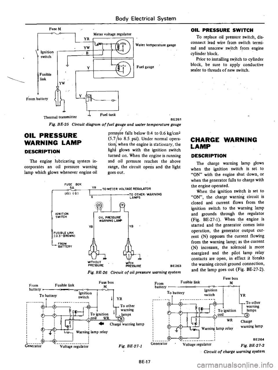
DESCRIPTION
The
engine
lubricating
system
in
corporates
an
oil
pressure
warning
lamp
which
glows
whenever
engine
oil
FUSE
BOX
SA
IGJ
G
YR
I
G
IGNITION
SWITCH
YB
I
FUSIBLE
LINK
O
J
BROWN
lffi
l
f
r@
Fuel
gauge
Fuel
tank
TO
METER
VOLTAGE
REGULATOR
TO
OTHER
WARNING
lAMPS
jt
Oil
PRESSURE
WARNING
LAhlP
YB
tl
PRESSURE
PRESSURE
FROM
BATTERY
BE263
Fig
BE
26
Circuit
of
oil
prelSure
warning
system
Fusible
link
Fuse
box
M
OIL
PRESSURE
SWITCH
To
replace
oil
pressure
switch
dis
connect
lead
wire
from
switch
termi
nal
and
unscrew
switch
from
engine
cylinder
block
Prior
to
installing
switch
to
cylinder
block
be
sure
to
apply
conductive
sealer
to
threads
of
new
switch
CHARGE
WARNING
LAMP
DESCRIPTION
The
charge
warning
lamp
glows
when
the
ignition
switch
is
set
to
ON
with
the
engine
shut
down
or
when
the
generator
falls
to
charge
with
the
engine
operated
When
the
ignition
switch
is
set
to
ON
the
charge
warning
circuit
is
closed
and
current
flows
from
the
ignition
switch
to
the
warning
lamp
and
grounds
through
the
regulator
Fig
BE
27
1
When
the
engine
is
started
and
the
generator
comes
into
operation
the
generator
output
cur
rent
N
opposes
th
current
flowing
from
the
warning
lamp
as
the
current
N
increases
the
solenoid
is
more
energized
and
the
pilot
lamp
relay
contacts
are
open
in
effect
it
oreaks
the
warning
circuit
ground
connection
and
the
lamp
goes
out
Fig
BE
27
2
Fusible
link
Fuse
box
M
From
battery
To
battery
Ig
ition
ru
nu
swllch
A
A
To
other
warning
h
To
ignition
IQlamps
i
J
r
coil
WR
t
I
j
Charge
warning
lamp
T
T
I
War
lamp
relay
J
I
Generator
v
it
ge
e
g
bt
From
battery
To
battery
Ignition
witch
J
i
L
r
t
ft
ignition
r
Glj
fCOil
WR
f
I
Warning
lamp
relay
Generator
Voltage
regulator
I
YR
Fig
BE
27
1
BE17
YR
UTO
other
warrung
lamps
Charge
warning
lamp
BE264
Fig
BE
27
2
Circuit
of
charge
warning
system
Page 465 of 537
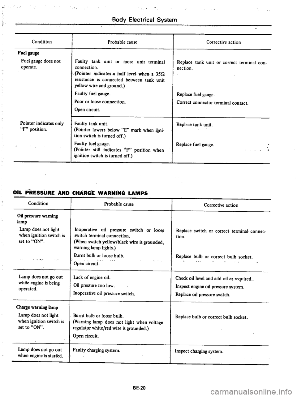
Condition
Fuel
gauge
Fuel
gauge
does
not
operate
Pointer
indicates
only
F
position
Body
Electrical
System
Probable
cause
Faulty
tank
unit
or
loose
unit
terminal
connection
pointer
indicates
a
half
level
when
a
35U
resistance
is
connected
between
tank
unit
yellow
wire
and
ground
Faulty
fuel
gauge
Poor
or
loose
cormection
Open
circuit
Faulty
tank
unit
pointer
lowers
below
E
mark
when
igni
tion
switch
Is
turned
off
Faulty
fuel
gauge
pointer
still
indicates
F
position
when
ignition
switch
is
turned
off
OIL
P
RESSURE
AND
CHARGE
WARNING
LAMPS
Condition
Oil
pressure
wamiug
lamp
Lamp
does
not
light
when
ignition
switch
is
set
to
ON
Lamp
does
not
go
out
while
engine
is
being
operated
OIarge
warning
lamp
Lamp
does
not
light
when
ignition
switch
is
set
to
ON
Lamp
does
not
go
out
when
engine
is
started
Probable
cause
Inoperative
oil
pressure
switch
or
loose
switch
terminal
connection
When
switch
yellow
black
wire
is
grounded
warning
lamp
lights
Burnt
bulb
or
loose
bulb
Open
circuit
Lack
of
engine
oil
Oil
pressure
too
low
Inoperative
oil
pressure
switch
Burnt
bulb
or
loose
bulb
Warning
lamp
does
not
light
when
voltage
regulator
white
red
wire
is
grounded
Open
circuit
Faulty
charging
system
BE
20
Corrective
action
Replace
tank
unit
or
correct
terminal
con
nection
Replace
fuel
gauge
Conect
connector
terminal
contact
Replace
tank
unit
Replace
fuel
gauge
Corrective
action
Replace
switch
OJ
correct
terminal
connee
tion
Replace
bulb
or
correct
bulb
socket
Check
oil
level
and
add
oil
as
required
Inspect
engine
oil
pressure
system
Replace
oil
pressure
switch
Replace
bulb
or
correct
bulb
socket
Inspect
charging
system
Page 475 of 537
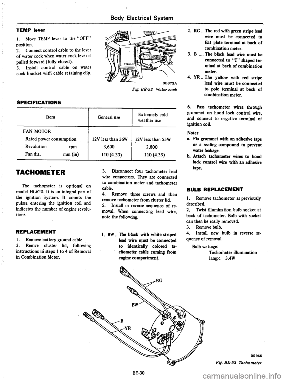
TEMP
lever
1
Move
TEMP
lever
to
the
OFF
position
2
Connect
control
cable
to
the
lever
of
water
ock
when
water
cock
lever
is
pulled
forward
fully
closed
3
Install
control
cable
on
water
cock
bracket
with
cable
retaining
clip
SPECIFICATIONS
Item
FAN
MOTOR
Rated
power
consumption
Revolution
rpm
Fan
dia
mm
in
TACHOMETER
The
tachometer
is
optional
on
model
HL620
It
is
an
integral
part
of
the
ignition
system
It
counts
the
pulses
entering
the
ignition
coil
and
indicates
the
number
of
engine
revolu
tions
REPLACEMENT
I
Remove
battery
ground
cable
2
Remve
cluster
lid
following
instructions
iri
steps
I
to
4
of
Removal
in
Combination
Meter
Body
Electrical
System
BE872A
Fig
BE
52
Water
cock
General
use
Extremely
cold
weather
use
2
RG
The
red
with
green
stripe
lead
wire
must
be
connected
to
flat
plate
terminal
at
back
of
combination
meter
3
B
The
black
lead
wire
must
be
connected
to
T
shaped
ter
minal
at
back
of
combination
meter
4
YR
The
yellow
with
red
stripe
lead
wire
must
be
connected
to
pole
terminal
at
back
of
combination
meter
6
Pass
tachllmeter
wires
through
grommet
on
hood
lock
control
wire
and
connect
to
negative
terminal
of
ignition
coil
Notes
a
Fix
grommet
with
an
adhesive
tape
or
a
sealing
compound
to
prevent
water
leakage
b
Attach
tachometer
wires
to
hood
lock
control
wire
with
an
adhesive
tape
BULB
REPLACEMENT
I
Remove
tachometer
as
previously
described
2
Twist
illumination
bulh
socket
at
back
of
tachometer
Bulb
with
socket
can
then
be
easily
removed
3
Remove
bulb
4
Install
new
bulb
in
reverse
se
quence
of
removal
Bulb
wattage
Tachometer
illumination
lamp
3
4W
12V
less
than
36W
3
600
110
433
12V
less
than
SSW
2
SOO
110
4
33
3
Disconnect
four
tachometer
lead
wire
connectors
They
are
connected
to
combination
meter
and
tachometer
cable
4
Remove
three
screws
and
then
remove
tachometer
from
cluster
lid
5
Install
in
reverse
sequence
of
re
moval
When
connecting
lead
wire
note
the
following
1
BW
The
black
with
white
striped
lead
wire
must
be
connected
to
identically
colored
ta
chometer
cable
coming
from
engine
compartment
BE
30
BE965
Fig
BE
53
Tachometer
Page 480 of 537
Body
Electrical
System
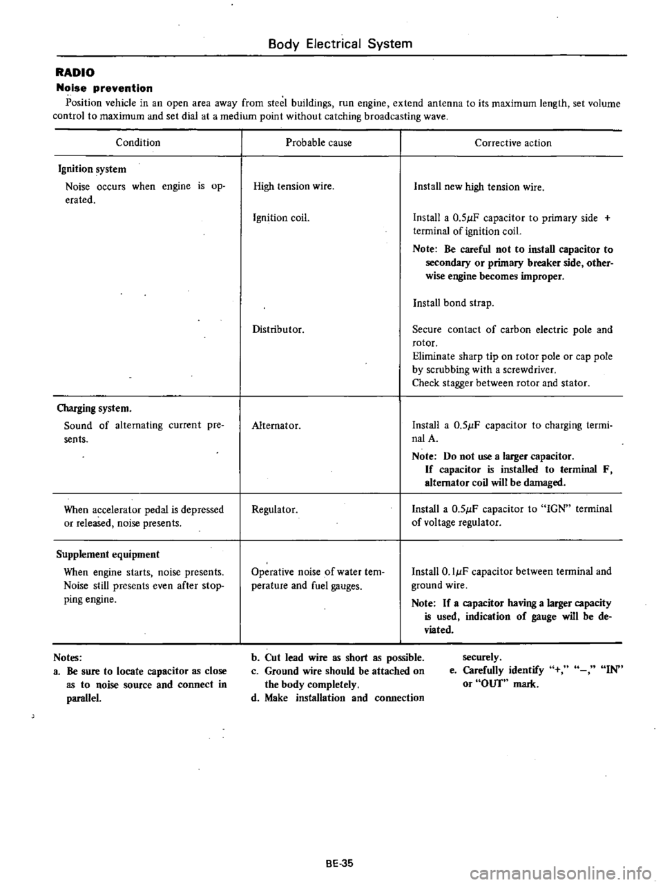
RADIO
Noise
prevention
Position
vehicle
in
an
open
area
away
from
steel
buildings
run
engine
extend
antenna
to
its
maximum
length
set
volume
control
to
maximum
and
set
dial
at
a
medium
point
without
catching
broadcasting
wave
Condition
Ignition
system
Noise
occurs
when
engine
is
op
erated
Charging
system
Sound
of
alternating
current
pre
sents
When
accelerator
pedal
is
depressed
or
released
noise
presents
Supplement
equipment
When
engine
starts
noise
presents
Noise
still
presents
even
after
stop
ping
engine
Notes
a
Be
sure
to
locate
capacitor
as
close
as
to
noise
source
and
connect
in
parallel
Probable
cause
Corrective
action
High
tension
wire
Install
new
high
tension
wire
Ignition
coil
Install
a
0
51lF
capacitor
to
primary
side
terminal
of
ignition
coil
Note
Be
careful
not
to
install
capacitor
to
secondary
or
primary
breaker
side
other
wise
engine
becomes
improper
Install
bond
strap
Distributor
Secure
contact
of
carbon
electric
pole
and
rotor
Eliminate
sharp
tip
on
rotor
pole
or
cap
pole
by
scrubbing
with
a
screwdriver
Check
stagger
between
rotor
and
stator
Alternator
Install
a
0
51lF
capacitor
to
charging
termi
nalA
Note
Do
not
use
a
larger
capacitor
If
capacitor
is
installed
to
terminal
F
alternator
coil
will
be
damaged
Regulator
Install
a
0
51lF
capacitor
to
IGN
terminal
of
voltage
regulator
Operative
noise
of
water
tem
perature
and
fuel
gauges
Install
O
IIlF
capacitor
between
terminal
and
ground
wire
Note
If
a
capacitor
having
a
larger
capacity
is
used
indication
of
gauge
will
be
de
viated
b
Cut
lead
wire
as
short
as
possible
c
Ground
wire
should
be
attached
on
the
body
completely
d
Make
installation
and
connection
securely
e
Carefully
identify
or
OUT
mark
IN
BE
35
Page 481 of 537

CD
m
Cl
@
D
@
I
j
1
To
instrument
harness
IS
To
battery
30
To
check
connector
2
To
full
transistor
amplifier
16
To
fusible
link
3t
To
headlamp
L
U
type
2
California
models
only
17
To
engine
harness
No
2
32
To
sido
marker
lamp
L
B
3
To
hood
switch
18
To
alternator
33
To
front
combination
lamp
L
H
4
To
engine
compartment
lamp
1
9
To
front
combination
lamp
R
n
34
To
horn
Low
ll
l
S
To
washer
motor
20
To
headlamp
R
H
type
2
3S
To
horn
High
l
l
0
6
To
auto
choke
heater
relay
1
To
side
marker
lamp
R
n
36
To
B
C
D
D
cut
olenoid
California
models
7
To
detector
dri
e
counter
22
To
headlamp
R
B
type
1
only
Non
Califunia
model
except
for
Canada
23
To
ground
37
To
block
tcrminal
distributor
California
8
To
ignition
relay
California
models
only
i4
To
thermal
transmitter
models
only
9
To
floor
sensor
relay
California
modeb
only
is
To
distributor
Non
California
models
only
38
To
ignition
coil
Non
California
models
only
n
10
To
inhibitor
relay
A
T
only
26
To
8
C
D
D
cut
solenoid
Non
California
39
To
condenser
t
II
To
head
lamp
relay
models
only
40
To
ignition
coil
and
resistor
@
12
To
horn
relay
27
To
fuel
cut
solenoid
California
models
only
OJ
v
m
13
To
voltage
regulator
28
To
auto
choke
heater
g
e
14
To
cooler
cable
29
To
headlamp
L
R
type
1
OJ
to
o
Q
m
r0
C
1
i
Ql
CIl
Il
l
3
Page 484 of 537

m
W
D
to
l
l
0
c
l
l
s
Q
3
For
Automatic
Transmission
LB
B
For
Manual
Transmission
m
For
Automatic
Transmission
COLOR
CODE
B
Black
BI
Brown
G
Green
L
Blue
Lg
Light
green
R
Red
W
White
Y
Yellow
BW
Black
with
white
stripe
LgR
Light
green
with
red
stripe
BY
RB
RB
B
WB
RB
YB
2
RB
I
B
1
BW
r
BY
LB
For
Automatic
Transmission
to
o
c
m
r0
O
O
Dl
For
Manual
Transmission
@
CJ
lti
3
RB
fB
BY
YB
RB@RB
YB
BY
1
To
kickdown
solenoid
fOT
Automatic
Transmission
2
To
reverse
switch
for
Manual
Tranmission
3
To
inhibitor
switch
for
Automatic
Transmission
4
To
oil
pressure
switch
5
To
starter
motor
6
To
engine
room
harness
for
Manual
Transmission
7
To
engine
room
harness
for
Automatic
Transmission
Page 486 of 537

@
BG
B
LW
LW
B
L
AL
l
J
YA
CD
m
LW
4
ft
GL
LR
t4
B
t
R
LG
4D
It
GW
BW
GW
L
@
ii
b
l
l
l
lD
m
en
lD
A
A
G
Ri
G
L
Non
California
except
Canada
I
G
GR
13
L
R
j
M
T
only
GL
A
T
only
To
engine
compartment
harness
Non
california
except
Canada
G
r
wRfl
Lt
IIY
LIB
l
ll
RY
R
oIll
CD
o
c
m
o
O
II
fJl
1
3
Page 497 of 537
REFRIGERAi
H
R
12
COMPRESSOR
OIL
MAINTENANCE
PERIODIC
MAINTENANCE
AND
SEASON
IN
INSPECTION
GENERAL
SERVICE
INSTRUCTION
SAFETY
PRECAUTIONS
EV
ACUA
TlNG
AND
CHARGING
SYSTEM
HANDLING
MANIFOLD
GAUGE
HANDLING
SERVICE
VALVE
HANDLING
CAN
TAP
DISCHARGING
SYSTEM
REFRIGERANT
R
12
The
refrigerant
used
in
the
air
conditioner
is
generally
called
Re
frigerant
12
R
12
No
other
refrig
erant
than
the
above
refrigerant
should
be
used
This
refrigerant
is
usually
available
in
a
small
can
or
a
cylinder
In
either
case
it
is
liquefied
under
high
pressure
in
the
container
Refrigerant
evaporates
easily
has
a
low
evaporation
point
and
moreover
since
the
latent
heat
of
the
refrigerant
is
large
it
can
abSorb
a
large
amount
of
heat
wh
err
e
vaporating
Extreme
care
must
be
exercised
when
handling
the
refrigerant
COMPRESSOR
OIL
The
SUNISO
5GS
or
SUNISO
351
should
be
used
as
refrigeration
lubricant
Mixing
of
the
two
is
allowable
The
refrigeration
lubricant
should
be
used
to
assure
the
successful
com
pressor
operation
Use
of
oils
other
than
recommended
or
mixing
of
the
oil
with
other
oils
would
cause
chemical
reaction
or
lead
to
lowered
viscosity
or
deficient
lubrication
The
oil
absorbs
moisture
as
it
con
tacts
the
air
This
points
out
the
need
for
care
not
to
expose
it
to
atmos
phere
for
an
extended
period
of
time
Air
Conditioning
GENERAL
SERVICE
CONTENTS
EVACUATING
SYSTEM
CHARGING
REFRIGERANT
CHECKING
FOR
LEAKS
HALIDE
LEAK
DETECTOR
ELECTRIC
LEAK
DETECTOR
REFRIGERANT
LEVEL
CHECK
SIGHT
GLASS
PERFORMANCE
TEST
COMPRESSOR
OIL
LEVEL
CHECK
PERFORMANCE
TEST
REFRIGERANT
LEAKS
AC
8
AC
8
AC
8
AC
8
AC
8
AC
9
AC
9
AC
9
AC10
AC
11
AC
12
MAINTENANCE
PERIODIC
MAINTENANCE
AND
SEASON
IN
INSPECTION
Both
periodic
maintenance
and
season
in
inspection
are
most
essential
to
enable
the
air
conditioner
to
give
full
performance
Perform
the
following
checks
Start
engine
and
check
refrigerant
level
through
sight
glass
on
receiver
dryer
For
details
refer
to
relative
topics
under
Refrigerant
Level
Check
2
Check
the
entire
sysiein
for
sign
of
refrigerant
leaks
Refer
to
relative
topics
under
Checking
for
Leaks
and
Refrigerant
Leaks
If
any
trace
of
oil
is
noted
at
and
around
connection
fittings
it
is
a
sure
indication
that
refrigerant
is
leaking
This
condition
can
be
corrected
easily
by
retightening
the
joints
If
any
joint
on
line
is
suspected
of
small
amount
of
leakage
use
a
leak
detector
to
locate
leaking
points
3
Check
compressor
drive
belts
for
proper
deflection
Season
off
Observe
the
following
maintenance
tips
to
allow
the
air
conditioner
to
operate
normally
in
the
next
season
I
Keep
the
entire
system
free
from
AC
8
AC12
AC
13
AC15
AC15
AC16
AC
16
AC16
AC
17
AC17
AC
17
AC18
refrigerant
leakage
by
periodically
checking
for
refrigerant
gas
leak
even
out
of
season
2
Turn
the
compressor
for
10
minutes
at
least
once
a
month
by
running
the
engine
at
1
500
rpm
c
ENERAL
SERVICE
INSTRUCTION
The
servicing
of
the
air
conditioner
should
be
carried
out
only
by
well
trained
servicemen
This
chapter
de
scribes
essential
points
of
servicing
Jf
a
Jarge
amount
of
dirt
and
sand
enter
the
system
they
will
be
carried
with
refrigerant
and
may
clog
the
system
or
scratch
rotating
parts
This
points
out
the
need
for
care
in
servicing
the
system
That
is
disconnecting
joints
should
be
carried
out
in
a
dean
place
Water
should
not
be
allowed
to
get
inside
the
system
The
refrigerant
does
not
readily
mix
with
water
However
the
presence
of
even
a
minute
amount
of
water
will
cause
a
chemical
reaction
at
high
tem
perature
which
will
in
turn
produce
hydrochloric
acid
HCl
Since
hydrochloric
acid
is
highly
corro
sive
to
metals
the
aluminum
and
copper
piping
etc
will
become
corroded
and
the
refrigeration
system
will
become
clogged