cooling DATSUN PICK-UP 1977 User Guide
[x] Cancel search | Manufacturer: DATSUN, Model Year: 1977, Model line: PICK-UP, Model: DATSUN PICK-UP 1977Pages: 537, PDF Size: 35.48 MB
Page 91 of 537
DESCRIPTION
COOLANT
LEVEL
DRAINING
AND
FLUSHING
THE
COOLING
SYSTEM
WATER
PUMP
REMOVAL
AND
INSTALLATION
DISASSEMBLY
INSPECTION
AND
ADJUSTMENT
TORQUE
COUPLING
REMOVAL
AND
INSTALLATION
DESCRIPTION
The
cooling
system
is
of
the
con
ventional
pressure
type
A
centrifugal
pump
installed
on
the
timing
chain
cover
serves
to
circulate
the
coolant
The
pressure
type
radiator
filler
cap
installed
on
the
radiator
operates
the
cooling
system
at
higher
than
atmos
pheric
pressure
The
higher
pressure
raises
the
boiling
point
of
the
coolant
and
in
Cooling
System
COOLING
SYSTEM
CONTENTS
CO
2
CO
2
OISASSEMBL
Y
INSPECTION
TEM
COUPLlNG
INSPECTION
THERMOSTAT
REMOVAL
AND
INSTALLATION
INSPECTION
RADIATOR
REMOVAL
AND
INSTALLATION
INSPECTION
CO
2
CO
2
CO
3
CO
3
CO
3
CO
3
CO
4
creases
the
cooling
efficiency
of
the
radiator
When
the
thermostat
is
closed
the
coolant
remains
in
the
cylinder
head
and
block
for
swift
warming
up
of
the
engine
After
it
reaches
normal
oper
ating
temperature
the
coolant
circu
lates
through
the
radiator
The
cooling
fan
drive
is
of
a
coupling
type
COOLANT
LEVEL
The
coolant
level
should
be
check
ed
and
maintained
at
SO
mm
1
97
in
below
the
upper
face
of
filler
neck
when
the
engine
is
cold
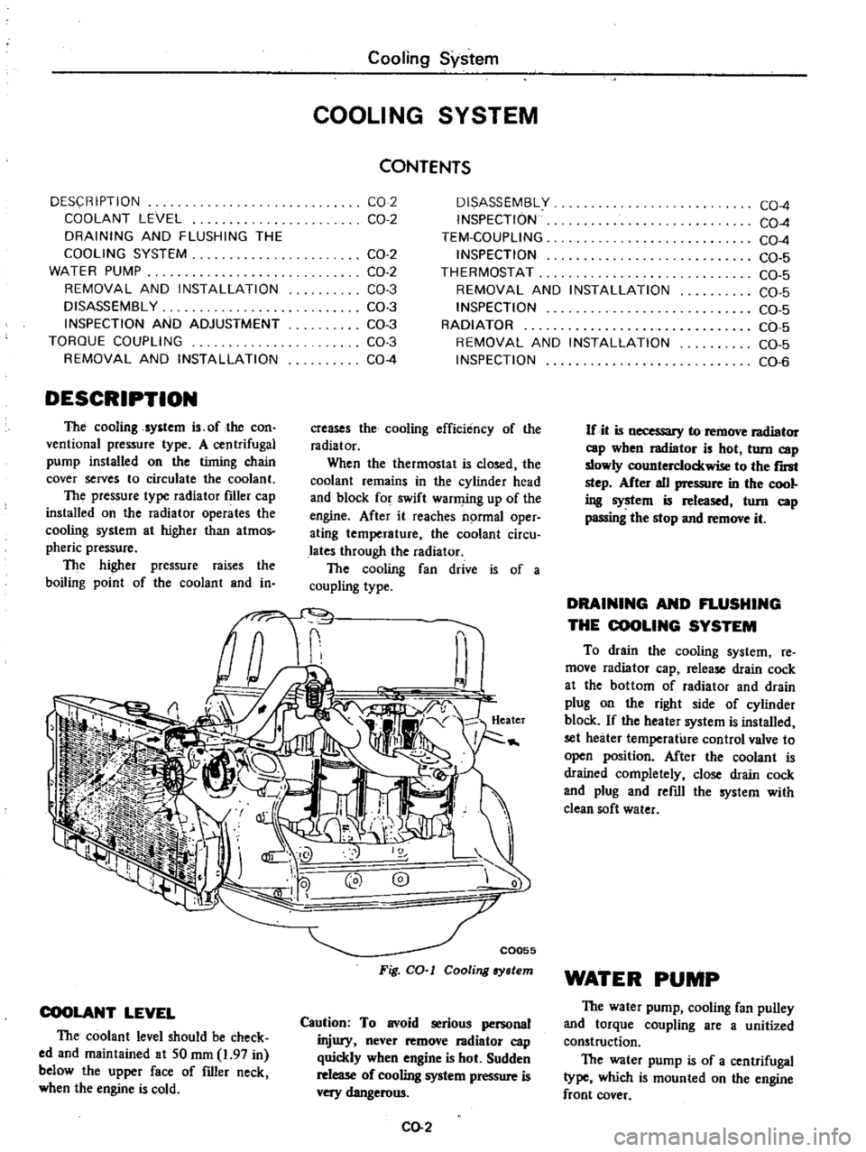
C0055
Fig
CO
I
Cooling
ry
lem
Caution
To
avoid
serious
personal
injury
never
remove
I3diator
cap
quickly
when
engine
is
hot
Sudden
release
of
cooling
system
pressure
is
very
dangerous
CO
2
CO
4
CO
4
CO
4
CO
5
CO
5
CO
5
CO
5
CO
5
CO
5
CO
6
If
it
is
necessary
to
remove
radiator
cap
wben
radiator
is
hot
turn
cap
slowly
counterclockwise
to
the
r
step
After
all
pressure
in
the
cool
ing
system
is
released
tom
cap
passing
the
stop
and
remove
it
DRAINING
AND
FLUSHING
THE
COOLING
SYSTEM
To
drain
the
cooling
system
re
move
radiator
cap
release
drain
cock
at
the
bottom
of
radiator
and
drain
plug
on
the
right
side
of
cylinder
block
If
the
heater
system
is
installed
set
heater
temperature
control
valve
to
open
position
After
the
coolant
is
drained
completely
close
drain
cock
and
plug
and
refill
the
system
with
clean
soft
water
WATER
PUMP
The
water
pump
cooling
fan
pulley
and
torque
coupling
are
a
unitized
construction
The
water
pump
is
of
a
centrifugal
type
which
is
mounted
on
the
engine
front
cover
Page 92 of 537
The
pump
shaft
is
supported
by
a
double
row
of
ball
bearings
press
fit
in
an
aluminum
die
cast
pump
body
The
bearings
are
permanently
lubricated
and
sealed
to
prevent
loss
of
lubricant
and
entry
of
dirt
The
pump
is
provided
with
an
impeller
which
turns
on
a
steel
shaft
The
steel
shaft
rotates
together
with
the
torque
coupling
wheeL
The
volute
chamber
is
built
in
the
engine
front
cover
assembly
The
inlet
of
the
pump
is
connected
to
the
radiator
s
lower
tank
by
a
hose
i
o
CQ047
Fig
CO
2
Water
pump
and
engine
front
cover
REMOVAL
AND
INSTALLATION
Removal
in
to
a
clean
con
assembly
I
CQ048
Fig
CO
3
Removing
water
pump
Installation
1
Be
sure
to
clean
the
gasket
sur
faces
in
contact
with
pump
and
front
cover
Always
use
new
gaskets
when
installing
pump
assembly
Be
sure
to
tighten
bolts
Cooling
System
Tightening
torque
0
4
to
0
5
kg
m
3
0
to
3
6
ft
lb
2
Fill
cooling
system
and
check
for
leaks
at
pump
3
Install
fan
blade
and
tighten
at
taching
bolts
securely
Install
belt
and
adjust
for
specified
tension
4
Operate
the
engine
at
fast
idling
and
recheck
for
leaks
5
Install
fan
shrouds
Note
Ensure
that
clearance
between
shroud
and
Can
is
even
at
any
place
DISASSEMBLY
Water
pump
is
made
of
aluminum
and
its
bearing
outer
race
is
of
a
press
fit
type
For
this
reason
water
pump
should
not
be
disassembled
INSPECTION
AND
ADJUSTMENT
Inspection
Inspect
pump
assembly
for
the
fol
lowing
conditions
and
replace
if
nee
essary
1
Badly
rusted
or
corroded
body
as
sembly
and
vane
2
Excessive
end
play
or
roughness
of
bearings
in
operation
3
Reduced
cooling
efficiency
due
to
deteriorated
silicone
oil
4
Oil
leakage
in
torque
coupling
Adjustment
Fan
belt
should
be
properly
ad
justed
at
all
times
A
tight
belt
causes
wear
of
alternator
and
water
pump
bearings
A
loose
belt
brings
about
improper
cooling
fan
water
pump
and
alternator
operation
Check
the
belt
slack
between
alter
nator
and
fan
pulley
by
force
of
10
kg
22
lb
Slackness
of
fan
belt
8
to
12
mm
0
31
to
0
47
in
If
adjustment
is
necessary
loosen
bolt
retaining
alternator
adjusting
bar
to
alternator
Move
alternator
toward
or
away
from
engine
until
the
correct
tension
is
obtained
TORQUE
COUPLING
Except
air
conditioner
equipped
models
The
torque
coupling
keeps
the
fan
speed
at
2
500
rpm
rated
or
below
to
conserve
horsepower
at
high
engine
speed
It
also
helps
reduce
fan
noise
to
a
minimum
during
high
speed
opera
tion
This
unit
is
filled
with
a
special
silicone
oil
used
as
a
fluid
coupling
which
controls
the
fan
speed
Silicone
oil
can
not
be
replenished
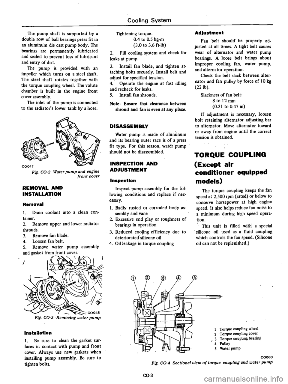
1
Torque
coupling
wheel
2
Torque
coupling
cover
3
Torque
coupling
bearing
4
Pulley
5
Water
pump
C0060
Fig
CO
4
Sectional
view
of
torque
coupling
and
water
pump
00
3
Page 93 of 537
REMOVAL
AND
INSTALLATION
To
replace
the
torque
coupling
follow
the
same
procedure
as
in
the
water
pump
The
torque
coupling
can
not
be
separated
from
the
water
pump
Cooling
System
DISASSEMBLY
The
torque
coupling
is
so
designed
that
it
can
not
be
disassembled
INSPECTION
Inspect
torque
coupling
for
oil
leakage
If
necessary
replace
TEM
COUPLl
G
For
air
conditioner
equipped
models
Tem
coupling
is
a
type
of
fan
coupling
which
is
provided
with
a
temperature
control
system
The
conventional
coupling
always
slips
the
fan
at
a
high
speed
under
a
constant
ratio
regardless
of
the
engine
cooling
requirement
The
slipping
ratio
of
the
Tern
coupling
however
is
properly
changed
with
the
cooling
requirement
ON
denotes
that
cooling
is
re
quired
and
the
fan
operates
up
to
about
2
150
rpm
When
high
cooling
is
not
required
during
cold
season
with
the
engine
warmed
up
etc
the
oper
w
6
I
1
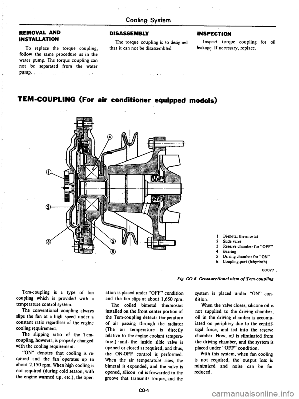
Bi
metal
thermostat
2
Slide
valve
3
Reserve
chamber
for
OFF
4
Bearing
5
Driving
chamber
for
ON
6
ouplingpart
labyrinth
coon
Fig
CO
5
CrQM
sectional
view
of
Tem
coupling
ation
is
placed
under
OFF
condition
and
the
fan
slips
at
about
1
650
rpm
The
coiled
bimetal
thermostat
installed
on
the
front
center
portion
of
the
Tem
coupling
detects
temperature
of
air
passing
through
the
radiator
The
air
temperature
is
directly
relative
to
the
engine
coolant
tempera
ture
and
the
inside
slide
valve
is
opened
or
closed
as
required
and
thus
the
ON
OFF
control
is
performed
When
the
air
temperature
rises
the
bimetal
is
expanded
and
the
valve
is
opened
silicon
oil
is
forwarded
to
the
groove
that
transmits
torque
and
the
CO
4
system
is
placed
under
ON
con
dition
When
the
valve
closes
silicone
oil
is
not
supplied
to
the
driving
chamber
oil
in
the
driving
chamber
is
accumu
lated
on
periphery
due
to
the
centrif
ugal
force
and
led
into
the
reserve
chamber
Now
oil
is
eliminated
from
the
driving
chamber
and
the
system
is
placed
under
OFF
condition
With
this
system
when
fan
cooling
is
not
required
the
output
loss
is
minimized
and
noise
can
be
far
reduced
Page 94 of 537
Conventional
COUplin9
WATER
PUMP
SPEED
F
Z
Tern
coupling
WATER
PUMP
SPEED
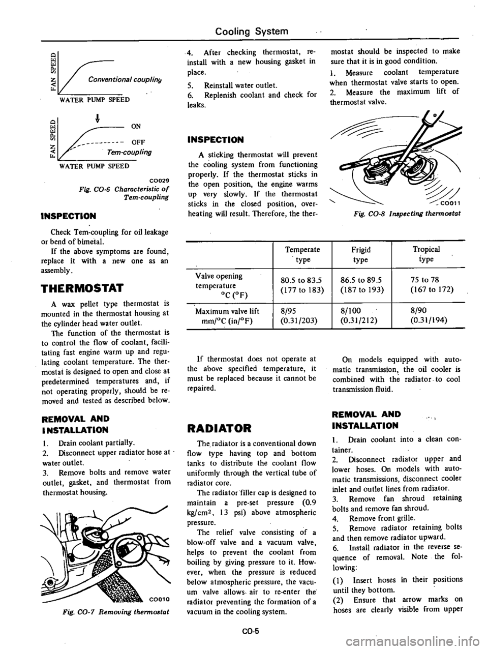
C0029
Fig
CO
6
Characteristic
of
Tern
coupling
INSPECTION
Check
Tem
coupling
for
oil
leakage
or
bend
of
bimetal
If
the
above
symptoms
are
found
replace
it
with
a
new
one
as
an
assembly
THERMOSTAT
A
wax
pellet
type
thermostat
is
mounted
in
the
thermostat
housing
at
the
cylinder
head
water
outlet
The
function
of
the
thermostat
is
to
control
the
flow
of
coolant
facili
tating
fast
engine
warm
up
and
regu
lating
coolant
temperature
The
ther
mostat
is
designed
to
open
and
close
at
predetermined
temperatures
and
if
not
operating
properly
should
be
re
moved
and
tested
as
described
below
REMOVAL
AND
INSTALLATION
I
Drain
coolant
partially
2
Disconnect
upper
radiator
hose
at
water
outlet
3
Remove
bolts
and
remove
water
outlet
gasket
and
thermostat
from
thermostat
housing
Fig
CO
7
Removing
therm06t
t
Cooling
System
4
After
checking
thermostat
re
install
with
a
new
housing
gasket
in
place
5
Reinstall
water
outlet
6
Replenish
coolant
and
check
for
leaks
INSPECTION
A
sticking
thermostat
will
prevent
the
cooling
system
from
functioning
properly
If
the
thermostat
sticks
in
the
open
position
the
engine
warms
up
very
slowly
If
the
thermostat
sticks
in
the
closed
position
over
heating
will
result
Therefore
the
ther
mostat
should
be
inspected
to
make
sure
that
it
is
in
good
condition
1
Measure
coolant
temperature
when
thermostat
valve
starts
to
open
2
Measure
the
maximum
lift
of
thermostat
valve
Fig
CO
S
Impecting
therm06t
t
Temperate
Frigid
Tropical
type
type
iype
Valve
opening
80
5
to
83
5
86
5
to
89
5
75
to
78
temperature
177
to
183
187
to
193
167
to
172
oC
OF
Maximum
valve
lift
8
95
8
1
00
8
90
mm
oC
in
F
0
31
203
0
31
212
0
31
194
If
thermostat
does
not
operate
at
the
above
specified
temperature
it
must
be
replaced
because
it
cannot
be
repaired
RADIATOR
The
radiator
is
a
conventional
down
flow
type
having
top
and
bottom
tanks
to
distribute
the
coolant
flow
uniformly
through
the
vertical
tube
of
radiator
core
The
radiator
filler
cap
is
designed
to
maintain
a
pre
set
pressure
0
9
kg
cm2
13
psi
above
atmospheric
pressure
The
relief
valve
consisting
of
a
blow
off
valve
and
a
vacuum
valve
helps
to
prevent
the
coolant
from
boiling
by
giving
pressure
to
it
How
ever
when
the
pressure
is
reduced
below
atmospheric
pressure
the
vacu
um
valve
allows
air
to
re
enter
the
radiator
preventing
the
formation
of
a
vacuum
in
the
cooling
system
CO
5
On
models
equipped
with
auto
matic
transmission
the
oil
cooler
is
combined
with
the
radiator
to
cool
transmission
fluid
REMOVAL
AND
INSTALLATION
Drain
coolant
into
a
clean
con
tainer
2
Disconnect
radiator
upper
and
lower
hoses
On
models
with
auto
matic
transmissions
disconnect
cooler
inlet
and
outlet
lines
from
radiator
3
Remove
fan
shroud
retaining
bolts
and
remove
fan
shroud
4
Remove
front
grille
5
Remove
radiator
retaining
bolts
and
then
remove
radiator
upward
6
Install
radiator
in
the
reverse
se
quence
of
removal
Note
the
fol
lowing
I
Insert
hoses
in
their
positions
until
they
bottom
2
Ensure
that
arrow
marks
on
hoses
are
clearly
visible
from
upper
Page 95 of 537
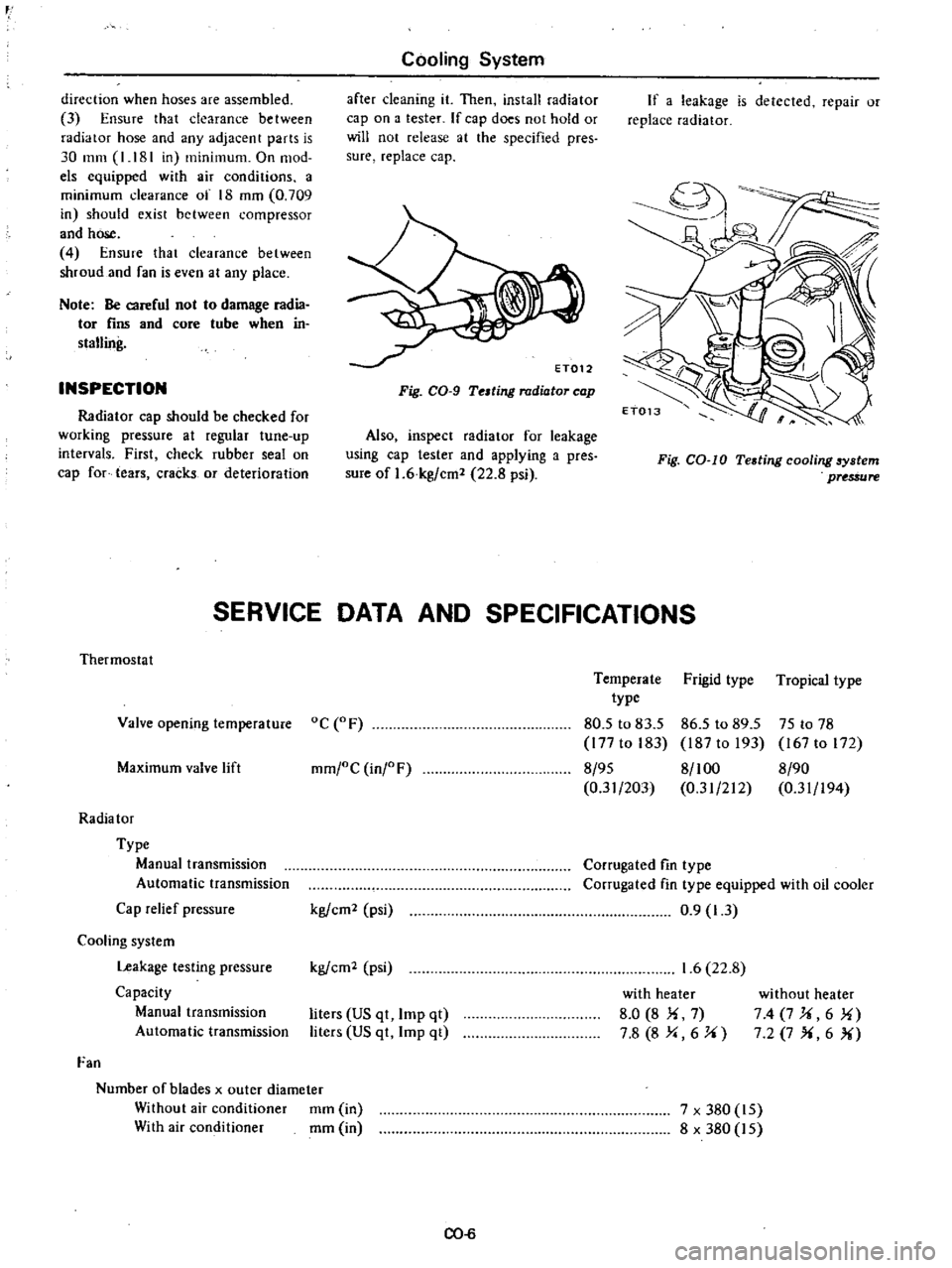
r
direction
when
hoses
are
assembled
3
Ensure
that
clearance
between
radiator
hose
and
any
adjacent
parts
is
30
mm
I
181
in
minimum
On
mod
els
equipped
with
air
conditions
a
minimum
clearance
of
18
mm
0
709
in
should
exist
between
compressor
and
hose
4
Ensure
that
clearance
between
shroud
and
fan
is
even
at
any
place
Note
Be
careful
not
to
damage
radia
tor
fins
and
core
tube
when
in
stalling
INSPECTION
Radiator
cap
should
be
checked
for
working
pressure
at
regular
tune
up
intervals
First
check
rubber
seal
on
cap
for
tears
cracks
or
deterioration
Cooling
System
after
cleaning
it
Then
install
radiator
cap
on
a
tester
If
cap
does
not
hold
or
will
not
release
at
the
specified
pres
sure
replace
cap
Fig
CO
9
Telting
radiator
cap
Also
inspect
radiator
for
leakage
using
cap
tester
and
applying
a
pres
sure
of
1
6
kg
cm
22
8
psi
If
a
leakage
is
detected
repair
or
replace
radiator
Fig
CO
IO
Testing
cooling
6ystem
pUS
ure
SERVICE
DATA
AND
SPECIFICATIONS
Thermostat
Valve
opening
temperature
oC
F
Maximum
valve
lift
mm
oC
inj
F
Radia
tor
Type
Manual
transmission
Automatic
transmission
Cap
relief
pressure
Cooling
system
Leakage
testing
pressure
Capacity
Manual
transmission
Automatic
transmission
Fan
Number
of
blades
x
outer
diameter
Without
air
conditioner
mm
in
With
air
conditioner
mm
in
kg
em
psi
kg
em
psi
liters
US
qt
Imp
qt
liters
US
qt
Imp
qt
CO
6
Temperate
Frigid
type
Tropical
type
type
80
5
to
83
5
86
5
to
89
5
75
to
78
177
to
183
187
to
193
167
to
172
8
95
8
100
8
90
0
31
203
0
31
212
0
31
194
Corrugated
fin
type
Corrugated
fin
type
equipped
with
oil
cooler
0
9
1
3
1
6
22
8
with
heater
8
0
8
Ii
7
7
8
8
Y
6
J
i
without
heater
74
7J
i6
1i
7
2
7
X
6
X
7
x
380
15
8
x
380
15
Page 96 of 537
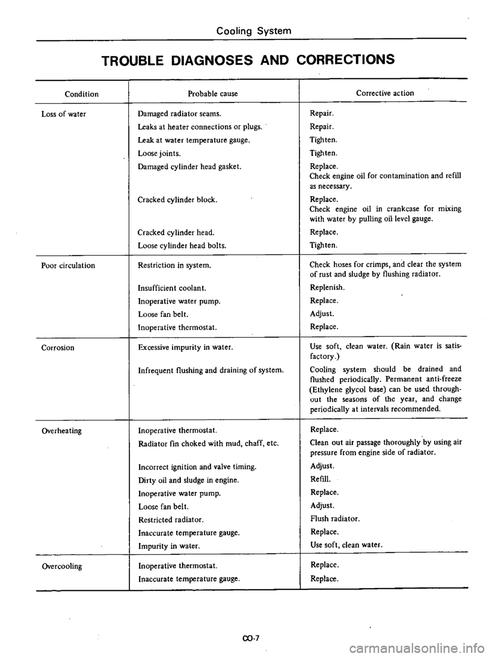
Condition
Loss
of
water
Poor
circulation
Corrosion
Overheating
Overcooling
Cooling
System
TROUBLE
DIAGNOSES
AND
CORRECTIONS
Probable
cause
Damaged
radiator
seams
Leaks
at
heater
connections
or
plugs
Leak
at
water
temperature
gauge
Loose
joints
Damaged
cylinder
head
gasket
Cracked
cylinder
block
Cracked
cylinder
head
Loose
cylinder
head
bolts
Restriction
in
system
Insufficient
coolant
Inoperative
water
pump
Loose
fan
belt
Inoperative
thermostat
Excessive
impurity
in
water
Infrequent
flushing
and
draining
of
system
Inoperative
thermostat
Radiator
fin
choked
with
mud
chaff
etc
Incorrect
ignition
and
valve
timing
Dirty
oil
and
sludge
in
engine
Inoperative
water
pump
Loose
fan
belt
Restricted
radiator
Inaccurate
temperature
gauge
Impurity
in
water
Inoperative
thermostat
Inaccurate
temperature
gauge
CO
7
Corrective
action
Repair
Repair
Tigh
ten
Tighten
Replace
Check
engine
oil
for
contamination
and
refill
as
necessary
Replace
Check
engine
oil
in
crankcase
for
mixing
with
water
by
pulling
oil
level
gauge
Replace
Tighten
Check
hoses
for
crimps
and
clear
the
system
of
rust
and
sludge
by
flushing
radiator
Replenish
Replace
Adjust
Replace
Use
soft
clean
water
Rain
water
is
satis
factory
Cooling
system
should
be
drained
and
flushed
periodically
Permanent
anti
freeze
Ethylene
glycol
base
can
be
used
through
out
the
seasons
of
the
year
and
change
periodically
at
intervals
recommended
Replace
Clean
out
air
passage
thoroughly
by
using
air
pressure
from
engine
side
of
radiator
Adjust
Refill
Replace
Adjust
Flush
radiator
Replace
Use
soft
clean
water
Replace
Replace
Page 314 of 537
Using
the
tester
check
the
two
black
yellow
BY
wires
from
the
in
hibitor
switch
in
the
ranges
N
and
I
and
the
tw
re
d
black
RBj
wir
s
in
the
range
R
for
continuity
Turn
range
select
lever
in
both
directions
from
each
lever
set
position
and
check
each
continuity
range
It
is
normal
if
the
electricity
is
on
while
the
lever
is
within
an
angle
of
about
30
on
both
sides
from
each
lever
set
line
How
ever
if
its
continl
ity
range
is
obvious
ly
unequal
on
both
sides
adjustment
is
required
If
any
malfunction
is
found
un
screw
the
fastening
nut
of
the
range
selector
lever
and
two
fastening
bolts
of
the
switch
body
and
then
remove
the
machine
screw
under
the
switch
body
Adjust
the
manual
shaft
correct
ly
to
the
position
N
by
means
of
the
selector
lever
When
the
slot
of
the
shaft
becomes
vertical
the
detent
works
to
position
the
shaft
correctly
with
a
clicking
sound
MSlVe
the
switch
slightly
asj
Je
so
that
the
screw
hole
will
be
aligned
with
the
pin
hole
of
the
internal
rotor
combined
with
the
manual
shaft
and
check
their
alignment
by
inserting
a
1
5
mm
0
059
in
diameter
pin
into
the
holes
If
the
alignment
is
correct
fasten
the
switch
body
with
the
bolts
pull
out
the
pin
tighten
up
the
screw
in
the
hole
and
fasten
the
selector
lever
as
before
Check
the
continuity
again
with
the
tester
If
the
malfunc
tion
still
remains
replace
the
inhibitor
switch
Chcck
whether
the
reverse
lamp
and
the
starter
motor
operate
normal
ly
in
these
ranges
If
Ihere
is
any
lrouble
first
check
the
linkage
If
no
fault
is
found
in
the
linkage
check
the
inhibitor
switch
Separate
the
manual
lever
from
Ihe
remote
control
selector
rod
and
turn
the
range
selcct
lever
to
N
Note
In
the
position
N
the
slot
of
the
manual
shaft
is
vertical
STALL
TEST
The
purpose
of
this
test
is
to
check
the
transmission
and
engine
for
trou
ble
by
measuring
the
maximum
num
bers
of
revolutions
of
the
engine
while
Automatic
Transmission
vehicle
is
held
in
a
stalled
condition
The
carburctor
is
in
full
throttle
opera
tion
with
the
selector
lever
in
ranges
f
2
and
I
respectively
Com
pare
the
measured
results
with
the
slandard
values
Components
to
be
tested
and
test
items
I
Clutches
brake
and
band
in
trans
mission
for
slipping
2
Torque
converter
for
proper
fune
tioning
3
Engine
for
overall
properly
STALL
TEST
PROCEDURES
Before
Icsting
c
heck
the
engine
oil
and
torque
converter
oil
warm
up
the
engine
cooling
water
to
suitable
tem
perature
by
running
at
1
200
rpm
with
the
selector
lever
in
the
range
P
for
several
minutes
Warm
up
the
torque
converter
oil
to
suitable
temperature
6010
1000C
140
to
2l20F
I
Mount
the
engine
tachometer
at
a
location
that
allows
good
visibility
fro
the
dri
er
s
seat
and
put
a
mark
on
specified
revolutions
on
the
meter
2
Secure
the
front
and
rear
wheels
with
chocks
and
apply
the
hand
brake
Be
sure
to
depress
the
brake
pedal
fumly
with
the
left
foot
before
de
pressing
the
accelerator
pedal
3
Throw
the
selector
lever
into
the
range
1
4
Slowly
depress
the
accelerator
pedal
until
the
throttle
valvc
is
fully
opened
Quickly
read
and
record
the
engine
revolution
when
the
engine
begins
to
rotate
steadily
and
then
release
the
accelerator
pedal
5
Shift
the
selector
lever
to
N
and
operate
the
engine
at
approxi
mately
1
200
rpm
for
more
than
one
minute
to
cool
down
the
torque
con
ver
ter
oil
and
coolant
6
Make
similar
stall
tests
in
ranges
2
I
and
RIO
Note
The
stall
test
operation
as
speci
f
d
in
item
4
should
be
I
l3de
wiihin
five
seconds
If
it
takes
too
long
the
oil
deteriorates
an
the
clutches
brake
and
band
are
ad
versely
affected
Sufficient
cooling
time
should
be
given
between
each
AT
5O
test
for
the
four
ranges
0
2
I
and
R
JUDGEMENT
High
stall
revolution
more
than
standard
revolution
If
the
engine
revolution
in
stall
condition
is
higher
than
the
standard
values
it
indicates
that
one
or
more
clutches
in
the
transmission
are
slipping
and
therefore
no
further
test
is
required
For
the
following
abnormalities
the
respective
causes
are
presumed
High
rpm
in
all
ranges
low
Iine
pressure
High
rpm
in
D
2
and
I
and
normal
rpm
in
R
Rear
clutch
slipping
High
rpm
in
0
and
normal
rpm
in
I
clutch
slipping
High
rpm
in
R
only
Front
clutch
or
low
and
reverse
brake
slipping
To
determine
which
is
slipping
front
clutch
or
low
and
reverse
brake
a
road
test
is
nceded
If
whilc
coasting
after
starting
with
the
lever
in
1
range
engine
braking
does
not
work
properly
the
low
and
reverse
brake
is
slipping
Otherwise
the
front
clutch
is
slipping
Slipping
of
the
band
brake
is
diffi
cult
to
ascertain
However
if
it
occurs
with
the
lever
in
2
range
engine
revolution
increases
Jp
to
thesarne
level
as
in
I
strange
It
is
impossible
to
check
it
in
the
stall
test
2
and
One
way
2
Standard
stall
revolution
If
the
engine
revolution
in
stall
condition
is
within
the
standard
values
the
control
elements
are
nor
mally
operating
in
the
ranges
0
2
I
and
R
Also
tIle
engine
and
one
way
clutch
of
the
torque
converter
are
normal
in
performance
and
operation
The
one
way
clutch
of
the
torque
converter
however
sometimes
sticks
This
is
determined
in
the
road
test
3
Lower
stall
revolution
than
stand
ard
revolution
If
the
engine
revolution
in
stall
condition
is
lower
than
the
standard
Page 323 of 537
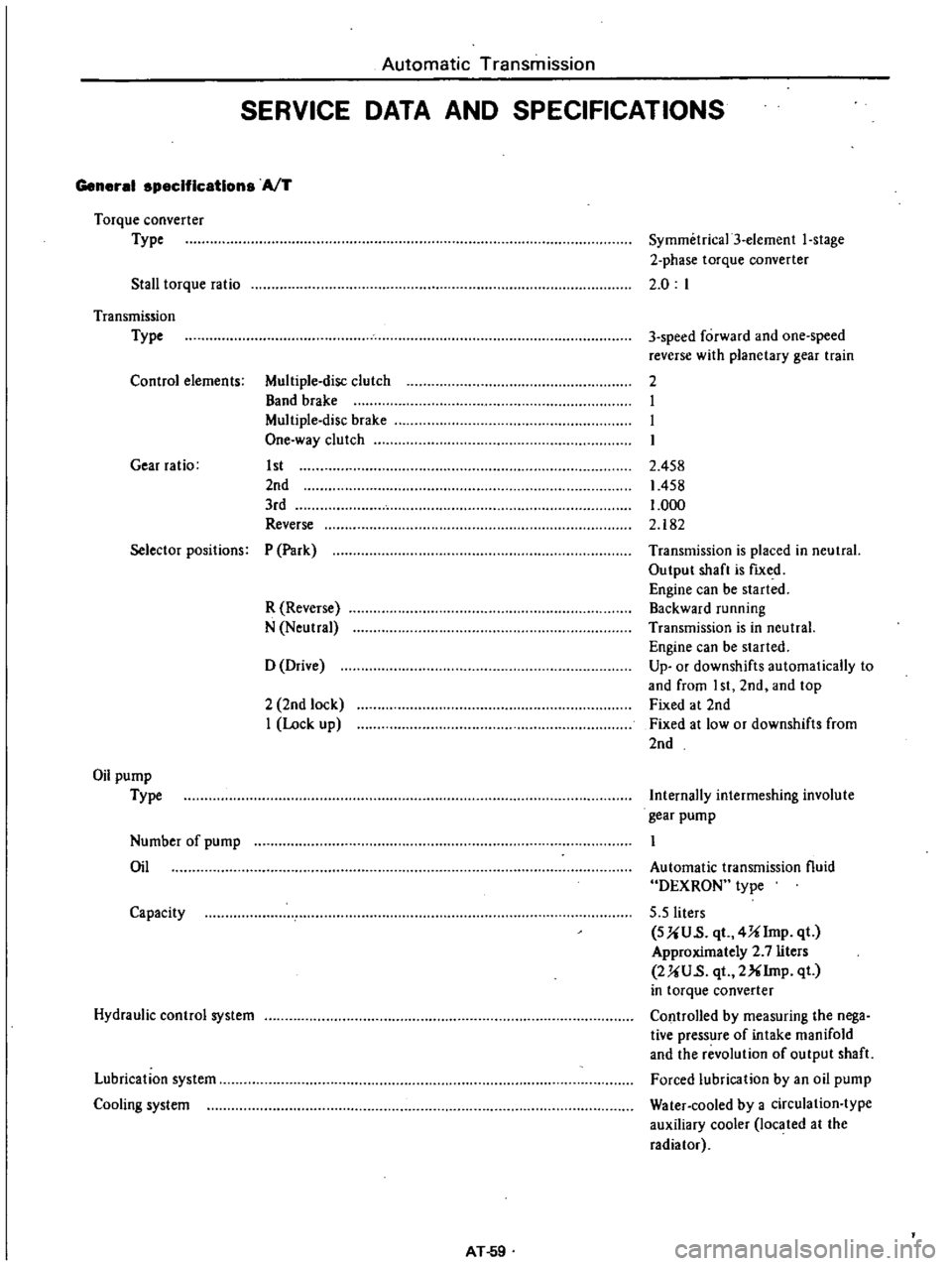
Automatic
Transmission
SERVICE
DATA
AND
SPECIFICATIONS
General
specifications
AfT
Torque
converter
Type
Stall
torque
ratio
Symmetrica13
element
I
stage
2
phase
torque
converter
2
0
I
Transmission
Type
Control
elements
Multiple
disc
clutch
Band
brake
Multiple
disc
brake
One
way
clutch
Gear
ratio
1st
2nd
3rd
Reverse
3
speed
forward
and
one
speed
reverse
with
planetary
gear
train
2
I
I
I
2
458
1458
1
000
2
182
Selector
positions
P
Park
R
Reverse
N
Neutral
Transmission
is
placed
in
neutral
Output
shaft
is
fIXed
Engine
can
be
started
Backward
running
Transmission
is
in
neutral
Engine
can
be
started
Up
or
downshifts
automatically
to
and
from
I
st
2nd
and
top
Fixed
at
2nd
Fixed
at
low
or
downshifts
from
2nd
o
Drive
2
2nd
lock
I
Lock
up
Oil
pump
Type
Internally
intermeshing
involute
gear
pump
Number
of
pump
Oil
Automatic
transmission
fluid
DEXRON
type
5
5
liters
SUU
s
qt
4Ulmp
qt
Approximately
2
7
liters
2UU
s
qt
2XIrnp
qt
in
torque
converter
Controlled
by
measuring
the
nega
tive
pressure
of
intake
manifold
and
the
revolution
of
output
shaft
Forced
lubrication
by
an
oil
pump
Water
cooled
by
a
circulation
type
auxiliary
cooler
located
at
the
radiator
Capacity
Hydraulic
control
system
Lubrication
system
Cooling
system
AT
59
Page 428 of 537
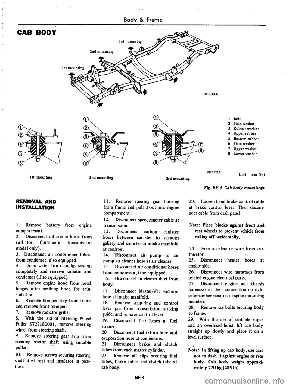
CAB
BODY
Body
Frame
Ist
mounting
2nd
mounting
1
Bolt
2
Plain
washer
3
Rubber
washer
4
Upper
rubber
5
Bottom
rubber
6
Plain
w
er
7
Upper
washer
8
Lower
washer
1st
mounting
REMOVAL
AND
INSTALLATION
Remove
battery
from
engine
compartment
2
Disconnect
oil
cooler
hoses
from
radiator
automatic
transmission
model
only
3
Disconnect
air
conditioner
tubes
from
condenser
if
so
equipped
4
Drain
water
from
cooling
system
completely
and
remove
radiator
and
condenser
if
so
equipped
5
Remove
engine
hood
from
hood
hinges
after
scribing
hood
for
rein
stallation
6
Remove
bumper
stay
from
frame
and
remove
front
bumper
7
Remove
radiator
grille
8
With
the
aid
of
Steering
Wheel
Puller
ST27
180001
remove
steering
wheel
from
steering
shaft
9
Remove
steering
gear
arm
from
steering
sector
shaft
using
suitable
puller
10
Remove
screws
securing
steering
shaft
dust
seat
and
insulator
in
posi
tion
2nd
mounting
3rd
mounting
II
Remove
steering
gear
housing
from
frame
and
pull
it
out
into
engine
compartment
12
Disconnect
speedometer
cable
at
transmission
1
3
Disconnect
carbon
canister
hoses
between
canister
to
vacuum
gallery
and
canister
to
intake
manifold
at
canister
14
Disconnect
air
pump
to
air
pump
air
cleaner
hose
at
air
cleaner
15
Disconnect
air
conditioner
hoses
from
compressor
if
so
equipped
16
Disconnect
air
cleaner
duct
from
body
17
Disconnect
Master
Vac
vacuum
hose
at
intake
manifold
18
Remove
snap
ring
and
control
lever
pin
from
transmission
striking
guide
and
remove
control
lever
19
Disconnect
fuel
hoses
at
fuel
strainer
20
Disconnect
fuel
return
hose
and
evaporation
hose
at
connectors
21
Disconnect
brake
and
clutch
tubes
from
each
master
cylinder
22
Remove
all
clips
securing
fuel
tubes
brake
tubes
and
clutch
tube
at
cab
body
BF
4
BF472A
Unit
mm
in
Fig
BF
4
Cab
body
mountings
23
Loosen
hand
brake
control
cable
at
brake
control
lever
Then
discon
nect
cable
from
dash
panel
Note
Place
blocks
against
front
and
rear
wheels
to
prevent
vehicle
from
rolling
off
accidentally
24
Free
accelerator
wire
from
car
buretor
25
Disconnect
heater
hoses
at
engine
side
26
Disconnect
wire
harnesses
from
related
engine
electrical
parts
27
Disconnect
engine
and
chassis
harnesses
at
their
connection
on
right
sidemember
near
rear
engine
mounting
member
28
Remove
six
bolts
securing
body
to
frame
29
With
the
use
of
suitable
ropes
and
an
overhead
hoist
lift
cab
body
straight
up
slowly
and
place
it
on
a
level
surface
Note
In
lifting
up
cab
body
use
care
not
to
dash
it
against
engine
or
rear
body
Cab
body
weighs
approxi
mately
220
kg
485
Ib
Page 461 of 537
REMOVAL
AND
INSTALLATION
I
Disconnect
battery
ground
cable
2
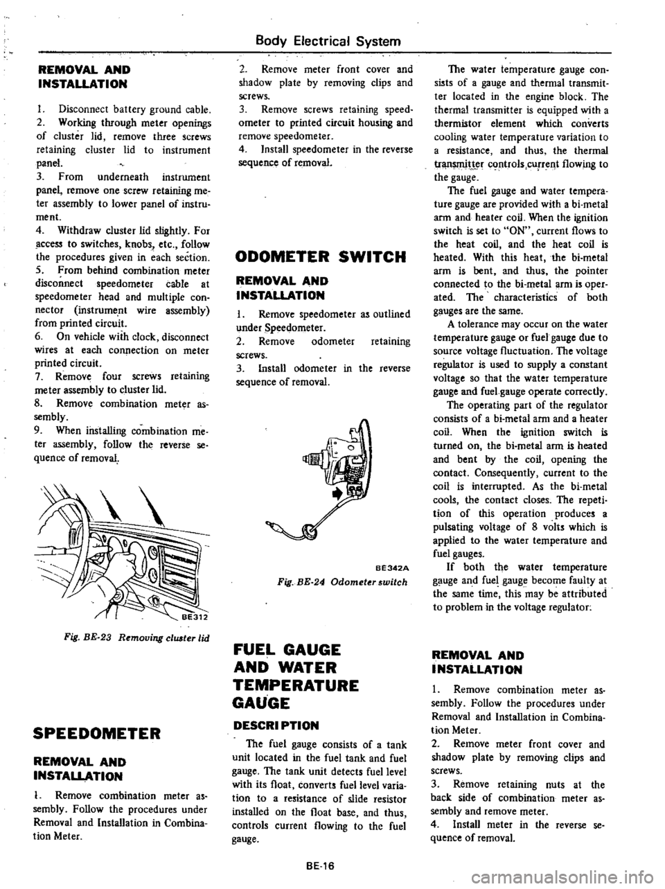
Working
through
meter
openings
of
cluster
lid
remove
three
screws
retaining
cluster
lid
to
instrument
panel
3
From
underneath
instrument
panel
remove
one
screw
retaining
me
ter
assembly
to
lower
panel
of
instru
ment
4
Withdraw
cluster
lid
slightly
For
ccess
to
switches
knobs
etc
follow
the
procedures
given
in
each
section
5
From
behind
combination
meter
disconnect
speedometer
cable
at
speedometer
head
and
multiple
con
nector
instrume
nt
wire
assembly
from
printed
circuit
6
On
vehicle
with
clock
disconnect
wires
at
each
connection
on
meter
printed
circuit
7
Remove
four
screws
retaining
me
ter
assembly
to
cluster
lid
8
Remov
combination
meter
as
sembly
9
When
installing
combination
me
ter
assembly
follow
the
reverse
se
quence
of
removal
Fig
BE
23
Removing
eluster
lid
SPEEDOMETER
REMOVAL
AND
INSTALLATION
1
Remove
combination
meter
as
sembly
Follow
the
procedures
under
Removal
and
Installation
in
Combina
tion
Meter
Body
Electrical
System
2
Remove
meter
front
cover
and
shadow
plate
by
removing
clips
and
screws
3
Remove
screws
retaining
speed
ometer
to
printed
circuit
housing
and
remove
speedometer
4
Install
speedometer
in
the
reverse
sequence
of
removal
ODOMETER
SWITCH
REMOVAL
AND
INSTALLATION
I
Remove
speedometer
as
outlined
under
Speedometer
2
Remove
odometer
retaining
screws
3
Install
odometer
in
the
reverse
sequence
of
removal
BE342A
Fig
BE
24
Odometerswitch
FUEL
GAUGE
AND
WATER
TEMPERATURE
GAUGE
DESCRI
PTION
The
fuel
gauge
consists
of
a
tank
unit
located
in
the
fuel
tank
and
fuel
gauge
The
tank
unit
detects
fuel
level
with
its
float
converts
fuel
level
varia
tion
to
a
resistance
of
slide
resistor
installed
on
the
float
base
and
thus
controls
current
flowing
to
the
fuel
gauge
BE16
The
water
temperature
gauge
con
sists
of
a
gauge
and
thermal
transmit
ter
located
in
the
engine
block
The
thermal
transmitter
is
equipped
with
a
thermistor
element
which
converts
cooling
water
temperature
variation
to
a
resistance
and
thus
the
thermal
tr
t
c
rtrols
cUfTent
flowing
to
the
gauge
The
fuel
gauge
and
water
tempera
ture
gauge
are
provided
with
a
bi
metal
arm
and
heater
coil
When
the
ignition
switch
is
set
to
ON
current
flows
to
the
heat
coil
and
the
heat
coil
is
heated
With
this
heat
the
bi
metal
arm
is
bent
and
thus
the
pointer
connected
to
the
bi
metal
arm
is
oper
ated
The
characteristics
of
both
gauges
are
the
same
A
tolerance
may
occur
on
the
water
temperature
gauge
or
fuel
gauge
due
to
source
voltage
fluctuation
The
voltage
regulator
is
used
to
supply
a
constant
voltage
so
that
the
water
temperature
gauge
and
fuel
gauge
operate
correctly
The
operating
part
of
the
regulator
consists
of
a
bi
metal
arm
and
a
heater
coil
When
the
ignition
switch
is
turned
on
the
bi
metal
arm
is
heated
and
bent
by
the
coil
opening
the
contact
Consequently
current
to
the
coil
is
interrupted
As
the
bi
metal
cools
the
contact
closes
The
repeti
tion
of
this
operation
produces
a
pulsating
voltage
of
8
volts
which
is
applied
to
the
water
temperature
and
fuel
gauges
If
both
the
water
temperature
gauge
and
fuel
gauge
become
faulty
at
the
same
time
this
may
be
attributed
to
problem
in
the
voltage
regulator
REMOVAL
AND
INSTALLATION
1
Remove
combination
meter
as
sembly
Follow
the
procedures
under
Removal
and
Installation
in
Combina
tion
Meter
2
Remove
meter
front
cover
and
shadow
plate
by
removing
clips
and
screws
3
Remove
retaining
nuts
at
the
back
side
of
combination
meter
as
sembly
and
remove
meter
4
Install
meter
in
the
reverse
se
quence
of
removal