engine coolant DATSUN PICK-UP 1977 User Guide
[x] Cancel search | Manufacturer: DATSUN, Model Year: 1977, Model line: PICK-UP, Model: DATSUN PICK-UP 1977Pages: 537, PDF Size: 35.48 MB
Page 153 of 537
E
G
R
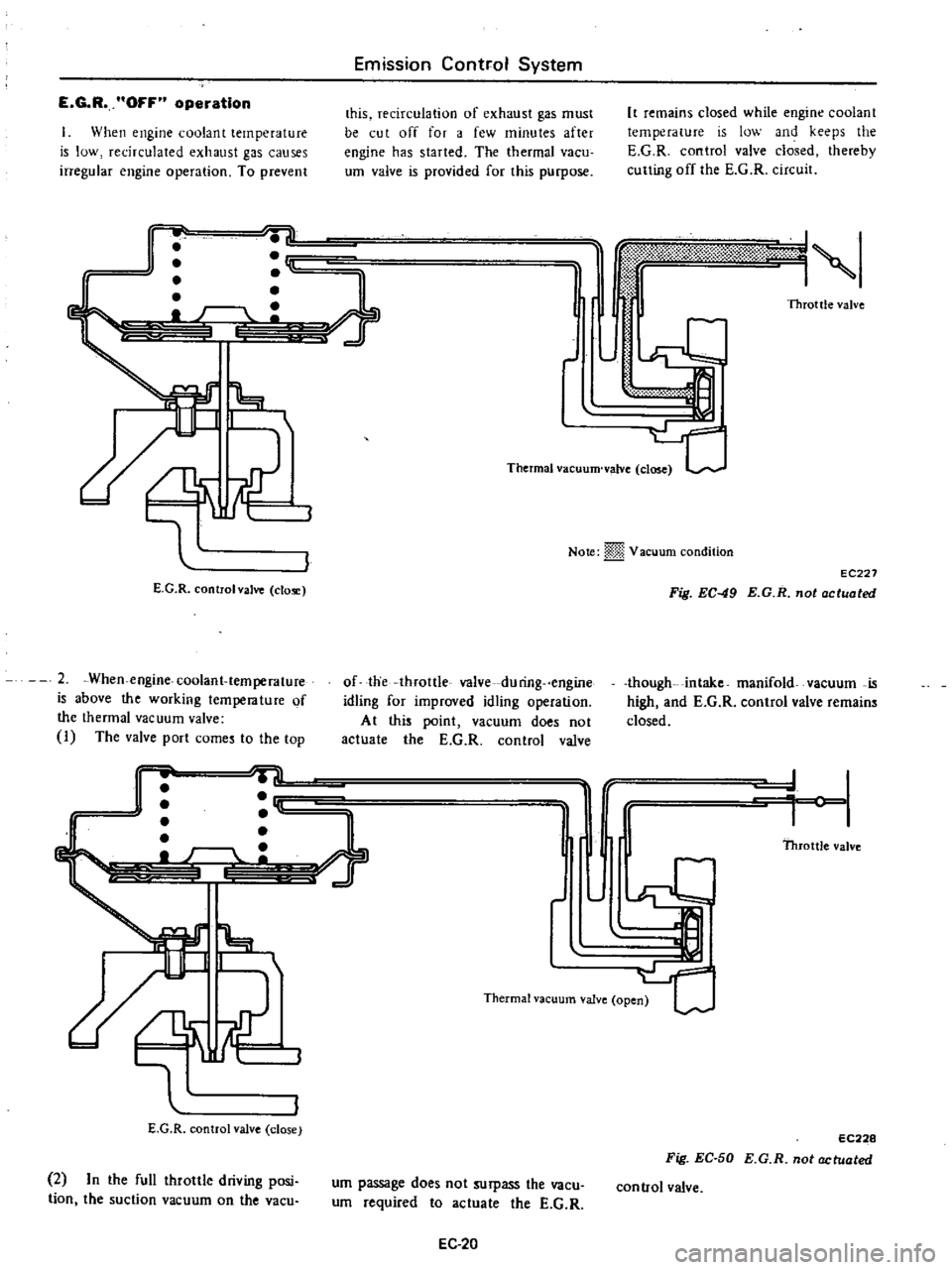
OFF
operation
When
engine
coolant
temperature
is
low
recirculated
exhaust
gas
causes
irregular
engine
operation
To
prevent
Emission
Control
System
this
recirculation
of
exhaust
gas
must
be
cut
off
for
a
few
minutes
after
engine
has
started
The
thermal
vacu
um
valve
is
provided
for
this
purpose
r
rn
11
L
e
7
E
G
R
controlval
le
clo
2
When
engine
coolant
temperature
is
above
the
working
temperature
of
the
thermal
vacuum
valve
I
The
valve
port
come
to
the
top
J
It
remains
closed
while
engine
coolant
temperature
is
low
and
keeps
the
E
G
R
control
valve
closed
thereby
culling
off
the
E
G
R
circuit
I
lW
jS
1
Throttle
valve
Thermal
vacuum
valve
close
j
Note
m
Vacuum
condition
of
the
throttle
valve
du
ring
engine
idling
for
improved
idling
operation
At
this
point
vacuum
does
not
actuate
the
E
G
R
control
valve
r
T
D
L
t
i
q
II
E
G
R
control
valve
close
2
In
the
full
throttle
driving
posi
tion
the
suction
vacuum
on
the
vacu
JllrI
Thermal
vacuum
valve
ope
um
passage
does
not
surpass
the
vacu
um
required
to
actuate
the
E
G
R
EC
20
EC227
Fig
EC
49
E
G
R
not
actuated
though
intake
manifold
vacuum
is
high
and
E
G
R
control
valve
remain
closed
l
Throttle
valve
EC228
Fig
EC
50
E
G
R
nol
actualed
control
valve
Page 154 of 537
6
Thermal
vacuum
valve
Open
E
G
R
control
valve
Close
E
G
R
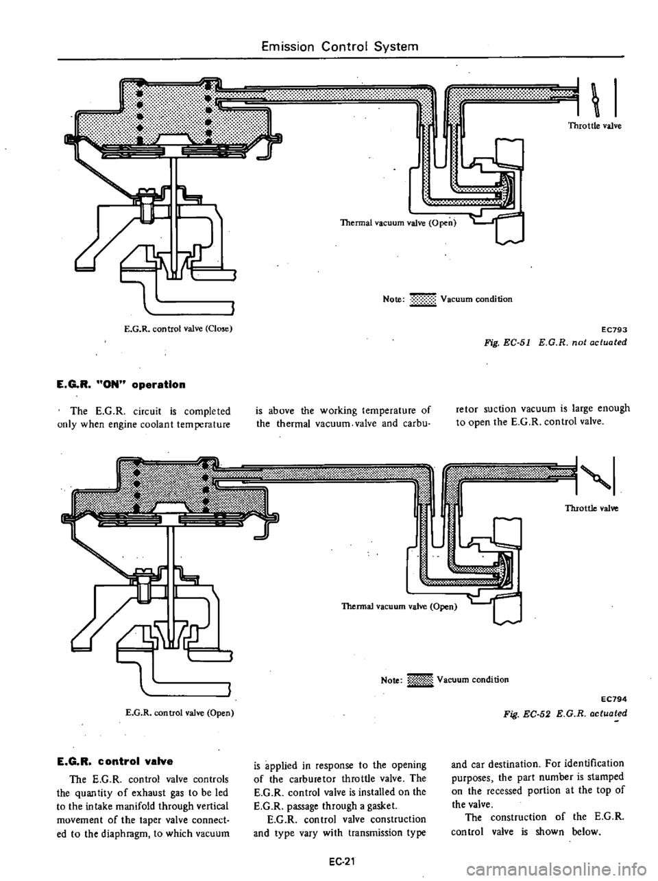
ON
operation
The
E
G
R
circuit
is
completed
only
when
engine
coolant
temperature
Emission
Control
System
I
I
Note
Vacuum
condition
EC793
Fig
EC
51
E
G
R
not
actuated
is
above
the
working
temperature
of
the
thermal
vacuum
valve
and
carbu
retor
suction
vacuum
is
large
enough
to
open
the
E
G
R
control
valve
Y
m
l
fj
t1f
1t
3
0
l
P
@
0
f
Y
f
1
i0
W
g
1
i3
iiA
d
m
E
N
ti
n
k
i
l
i
Throttle
valve
n
L
r
E
G
R
control
valve
Open
E
G
R
control
valva
The
E
G
R
control
valve
controls
the
quantity
of
exhaust
gas
to
be
led
to
the
intake
manifold
through
vertical
movement
of
the
taper
valve
connect
ed
to
the
diaphragm
to
which
vacuum
Thermal
vacuum
valve
Open
Note
iiiI
Vacuum
condition
EC794
Fig
EC
52
E
G
R
actuated
is
applied
in
response
to
the
opening
of
the
carburetor
throttle
valve
The
E
G
R
control
valve
is
installed
on
the
E
G
R
passage
through
a
gasket
E
G
R
con
trol
valve
construction
and
type
vary
with
transmission
type
and
car
destination
For
identification
purposes
the
part
number
is
stamped
on
the
recessed
portion
at
the
top
of
the
valve
The
construction
of
the
E
G
R
control
valve
is
shown
below
EC
21
Page 156 of 537
1
1
I
I
I
1
v
v
I
I
I
I
I
I
I
I
I
I
I
I
I
I
I
I
I
I
I
I
I
L
0
I
Magnet
coil
Detector
drive
counter
REMOVAL
AND
INSTALLATION
Remove
air
cleaner
before
removing
E
G
R
control
system
For
removal
and
installation
of
air
cleaner
refer
to
Air
Cleaner
section
Page
EF
S
Removal
I
E
G
R
control
valve
After
removing
the
following
parts
the
E
G
R
controi
valve
can
be
dis
mounted
Vacuum
hose
thermal
vacuum
valve
to
E
G
R
control
valve
E
G
R
control
valve
mounting
nut
Note
To
remove
vacuum
hose
flat
ten
clip
connecting
vacuum
hose
to
E
G
R
control
valve
and
pull
the
hose
off
with
hand
Emission
Control
System
Ignition
switch
E
G
R
warning
lamp
f
1
Ignition
switch
start
position
Fuse
1
A
Odometer
switch
r
I
I
I
I
v
I
I
I
i
lQ
U
1
mi
L
J
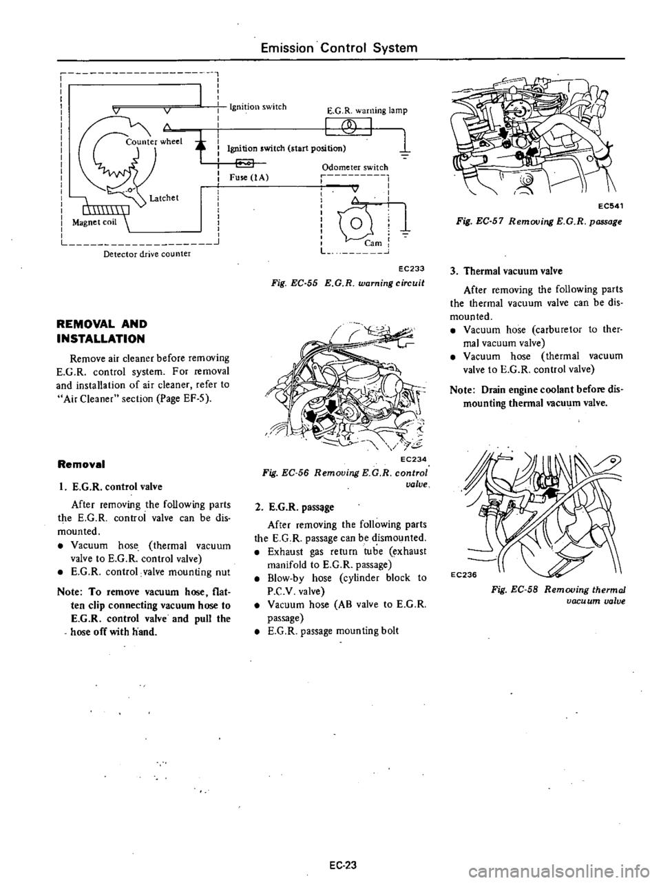
EC233
Fig
EC
55
E
G
R
warning
circuit
EC234
Fig
EC
56
Removing
KG
R
control
valve
2
E
G
R
pass
ge
After
removing
the
following
parts
the
E
G
R
passage
can
be
dismounted
Exhaust
gas
return
tube
exhaust
manifold
to
E
G
R
passage
B1ow
by
hose
cylinder
block
to
P
C
v
valve
Vacuum
hose
AB
valve
to
E
G
R
passage
E
G
R
passage
mounting
bolt
EC
23
EC541
Fig
EC
57
Removing
E
G
R
passage
3
Thermal
vacuum
valve
After
removing
the
following
parts
the
thermal
vacuum
valve
can
be
dis
mounted
Vacuum
hose
carburetor
to
ther
mal
vacuum
valve
Vacuum
hose
thermal
vacuum
valve
to
E
G
R
control
valve
Note
Drain
engine
coolant
before
dis
mounting
thermal
vacu
m
valve
Fig
EC
58
Removing
thermal
vacu
um
valve
Page 158 of 537
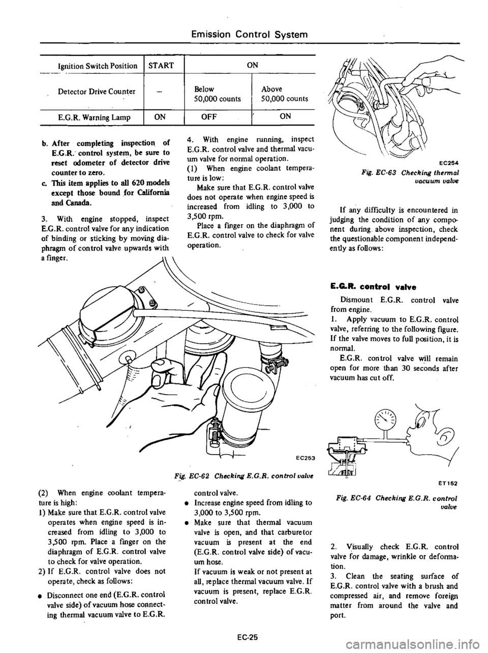
Ignition
Switch
Position
START
Detector
Drive
Counter
E
G
R
Warning
Lamp
ON
b
After
completing
inspection
of
E
G
R
control
system
be
sure
to
reset
odometer
of
detector
drive
counter
to
zero
c
This
item
applies
to
all
620
models
except
those
bound
for
California
and
Canada
3
With
engine
stopped
inspect
E
G
R
control
valve
for
any
indication
of
binding
or
sticking
by
moving
dia
phragm
of
control
valve
upwards
with
a
finger
2
When
engine
coolant
tempera
ture
is
high
I
Make
sure
that
E
G
R
control
valve
operates
when
engine
speed
is
in
creased
from
idling
to
3
000
to
3
500
rpm
Place
a
fmger
on
the
diaphragm
of
E
G
R
control
valve
to
check
for
valve
operation
2
If
E
G
R
control
valve
does
not
operate
check
as
follows
Disconnect
one
end
E
G
R
control
valve
side
of
vacuum
hose
connect
ing
thermal
vacuum
valve
to
E
G
R
Emission
Control
System
ON
Below
50
000
counts
Above
50
000
counts
OFF
ON
4
With
engine
running
inspect
E
G
R
control
valve
and
thermal
vacuo
um
valve
for
normal
operation
1
When
engine
coolant
tempera
ture
is
low
Make
sure
that
E
G
R
control
valve
does
not
operate
when
engine
speed
is
increased
from
idling
to
3
000
to
3
500
rpm
Place
a
fmger
on
the
diaphragm
of
E
G
R
control
valve
to
check
for
valve
operation
EC253
Fig
EC
62
Checking
E
G
R
control
valve
control
valve
Increase
engine
speed
from
idling
to
3
000
to
3
500
rpm
Make
su
re
that
thermal
vacu
um
valve
is
open
and
that
carburetor
vacuum
is
present
at
the
end
E
G
R
control
valve
side
of
vacu
um
hose
If
vacuum
is
weak
or
not
present
at
all
replace
thermal
vacuum
valve
If
vacuum
is
present
replace
E
G
R
control
valve
EC
25
EC254
Fig
EC
63
Checking
lhermal
vacuum
valve
If
any
difficulty
is
encountered
in
judging
the
condition
of
any
compo
nent
during
above
inspection
check
the
questionable
component
independ
ently
as
follows
E
G
R
control
valve
Dismount
E
G
R
control
valve
from
engine
I
Apply
vacuum
to
E
G
R
control
valve
referring
to
the
following
figure
If
the
valve
moves
to
full
position
it
is
normal
E
G
R
control
valve
will
remain
open
for
more
than
30
seconds
after
vacuum
has
cut
off
la
ET152
Fig
EC
64
Checking
E
G
R
control
ualue
2
Visually
check
E
G
R
control
valve
for
damage
wrinkle
or
defonna
tion
3
Clean
the
seating
surface
of
E
G
R
control
valve
with
a
brush
and
compressed
air
and
remove
foreign
matter
from
around
the
valve
and
port
Page 159 of 537
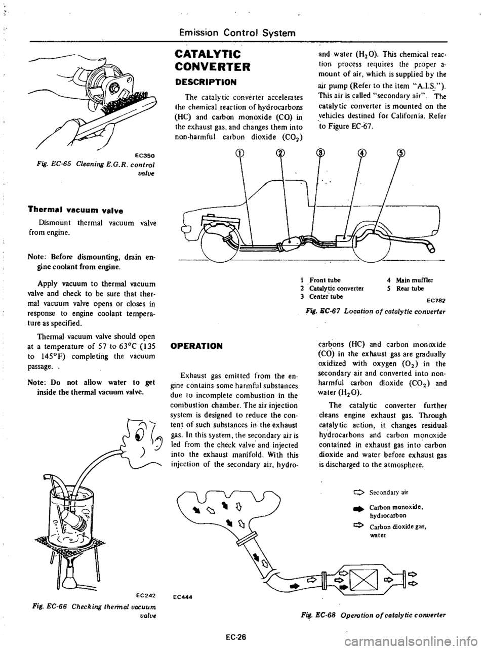
EC350
Fig
EC
65
Cleaning
E
G
R
control
valve
Thermal
vacuum
valve
Dismount
thermal
vacuum
valve
from
engine
Note
Before
dismounting
drain
en
gine
coolant
from
engine
Apply
vacuum
to
thermal
vacuum
valve
and
check
to
be
sure
thaI
ther
mal
vacuum
valve
opens
or
closes
in
response
to
engine
coolant
tempera
ture
as
specified
Thermal
vacuum
valve
should
open
at
a
temperature
of
57
to
630C
135
to
1450F
completing
the
vacuum
passage
Note
Do
not
allow
water
to
get
inside
the
thermal
vacuum
valve
EC242
Fig
EC
66
Checking
hennal
vacuum
valve
Emission
Control
System
CATALYTIC
CONVERTER
DESCRIPTION
The
catalytic
converter
accelerates
the
chemical
reaction
of
hydrocarbons
HC
and
carbon
monoxide
CO
in
the
exhaust
gas
and
changes
them
into
non
harmful
carbon
dioxide
C02
OPERATION
Exhaust
gas
emitted
from
the
en
gine
contains
some
harmful
substances
due
to
incomplete
combustion
in
the
combustion
chamber
The
air
injection
system
is
designed
to
reduce
the
con
tent
of
such
substances
in
the
exhaust
gas
In
this
system
the
secondary
air
is
led
from
the
check
valve
and
injected
into
the
exhaust
manifold
With
this
injection
of
the
secondary
air
hydro
EC444
EC
26
and
water
H20
This
chemical
reac
tion
process
requires
the
proper
a
mount
of
air
which
is
supplied
by
the
air
pump
Refer
to
the
item
AJ
S
This
air
is
caUed
secondary
air
The
catalytic
converter
is
mounted
on
the
vehicles
destined
for
California
Refer
to
Figure
EC
67
3
4
1
Front
tube
2
Catalyti
converter
3
Center
tube
4
Main
muffler
5
Rear
tube
EC782
Fig
EC
67
Location
of
catalytic
converter
car
ons
He
and
carbon
monoxide
CO
in
the
exhaust
gas
are
gradually
oxidized
with
oxygen
02
in
the
secondary
air
and
converted
into
non
harmful
carbon
dioxide
C02
and
water
H20
The
catalytic
converter
further
cleans
engine
exhaust
gas
Through
catalytic
action
it
changes
residual
hydrocarbons
and
carbon
monoxide
contained
in
exhaust
gas
into
carbon
dioxide
and
water
before
exhaust
gas
is
discharged
to
the
atmosphere
c
Secondary
air
Carbon
monoxide
hydrocarbon
Carbon
dioxide
gas
water
F
EC
68
Operution
of
catalytic
corwerter
Page 219 of 537
Engine
Removal
Installation
ENGINE
REMOVAL
AND
INSTAllATION
REMOVAL
INSTALLATION
ENGINE
MOUNTING
INSULATORS
REMOVAL
It
is
much
easier
to
remove
engine
and
transmission
as
a
single
unit
than
to
remove
them
separately
After
re
moval
engine
can
be
separated
from
transntission
assembly
Notes
a
Be
sure
to
hoist
engine
and
jack
up
transmission
in
a
safe
manner
b
Use
fender
cove
to
protect
vehicle
body
1
Remove
battery
2
Scribe
hood
hinge
location
for
proper
reinstallation
and
remove
hood
Note
Have
an
assistant
help
you
so
as
to
prevent
damage
to
body
3
Drain
radiator
coolant
4
Disconnect
upper
and
lower
radiator
hoses
from
engine
5
Remove
two
oil
cooler
hoses
from
lower
end
of
radiator
Auto
ma
tic
transmission
models
only
6
Remove
radiator
shroud
7
Remove
four
bolts
securing
radia
tor
and
detach
radiator
Note
Always
tighten
securing
bolt
at
upper
right
hand
side
together
with
body
harness
terminal
8
Remove
carburetor
air
cleaner
as
follows
Remove
fresh
air
duct
Remove
hot
air
duct
Loosen
air
cleaner
band
bolt
and
air
cleaner
supporting
bolts
Disconnect
air
cleaner
ta
air
pump
hose
Disconnect
air
cleaner
to
rocker
cover
hose
at
rocker
cover
Disconnect
air
cleaner
to
air
control
valve
hose
California
models
only
CONTENTS
ER
2
ER
3
ER
3
FRONT
INSULATOR
REAR
INSULATOR
TIGHTENING
TORQUE
ER
4
ER
4
ER
4
Disconnect
air
deaner
to
A
B
valve
hose
Disconnect
air
cleaner
ta
vacuum
hoses
Note
Protect
carburetor
from
dust
and
foreign
matter
by
placing
cover
over
air
inlet
opening
9
Disconnect
fuel
pump
to
fuel
fdter
hose
and
return
hose
10
Disconnect
carbon
canister
hose
on
engine
side
II
Disconnect
air
pump
air
C1eaner
to
al
p
p
hose
12
Disconnect
following
cables
wires
and
hoses
Engine
ground
cable
Accelerator
wire
at
carburetor
High
tension
cable
between
ignition
coil
and
distributor
Wire
to
distributor
at
body
ter
minal
Wire
to
oil
pressure
switch
Wires
to
thermal
transmitter
Wires
to
B
C
p
D
cut
solenoid
Non
California
models
only
auto
choke
heater
and
anti
dieseling
solenoid
Wires
to
alternator
Wires
to
starter
motor
Heater
inlet
and
outlet
hoses
if
so
equipped
Vacuum
hose
of
Master
Vac
at
in
taJce
manifold
Wires
for
back
up
lamp
switch
Cable
to
speedometer
13
Remove
transmission
control
linkage
from
transmission
Manual
transmission
models
I
Detach
rubber
boot
2
Remove
E
ring
and
control
lever
pin
from
transmission
striking
rod
guide
and
remove
control
lever
ER
2
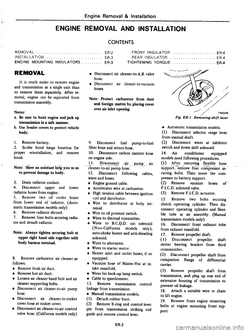
Fig
ER
l
Automatic
transmission
models
I
Disconnect
selector
range
lever
from
manual
shaft
2
Disconnect
wires
at
inhibitor
switch
and
down
shift
solenoid
14
Air
conditioner
equipped
models
need
following
procedures
1
After
removing
flexible
hose
support
remove
four
comi
ressor
se
curing
bolts
Then
move
the
com
pressor
to
battery
support
2
Remove
vacuum
hoses
of
F
LC
D
solenoid
valve
3
Remove
F
LC
D
actuator
15
Remove
two
bolts
securing
clutch
operating
cylinder
Then
dis
connect
operating
cylinder
and
flexi
ble
tube
as
an
assembly
Manual
transmission
models
only
16
Disconnect
front
exhaust
tube
from
exhaust
manifold
17
Remove
propeller
shaft
I
Disconnect
propeller
shaft
center
bearing
bracket
from
third
crossmember
2
Disconnect
propeller
shaft
from
companion
flange
of
differential
carrier
3
Remove
propeller
shaft
from
transmission
and
plug
up
rear
end
of
extension
housing
of
transmission
to
prevent
oil
leakage
18
Attach
a
suitable
wire
or
chain
to
lift
engine
19
Remove
front
engine
mounting
bolts
at
engine
mounting
front
sup
port
Page 314 of 537
Using
the
tester
check
the
two
black
yellow
BY
wires
from
the
in
hibitor
switch
in
the
ranges
N
and
I
and
the
tw
re
d
black
RBj
wir
s
in
the
range
R
for
continuity
Turn
range
select
lever
in
both
directions
from
each
lever
set
position
and
check
each
continuity
range
It
is
normal
if
the
electricity
is
on
while
the
lever
is
within
an
angle
of
about
30
on
both
sides
from
each
lever
set
line
How
ever
if
its
continl
ity
range
is
obvious
ly
unequal
on
both
sides
adjustment
is
required
If
any
malfunction
is
found
un
screw
the
fastening
nut
of
the
range
selector
lever
and
two
fastening
bolts
of
the
switch
body
and
then
remove
the
machine
screw
under
the
switch
body
Adjust
the
manual
shaft
correct
ly
to
the
position
N
by
means
of
the
selector
lever
When
the
slot
of
the
shaft
becomes
vertical
the
detent
works
to
position
the
shaft
correctly
with
a
clicking
sound
MSlVe
the
switch
slightly
asj
Je
so
that
the
screw
hole
will
be
aligned
with
the
pin
hole
of
the
internal
rotor
combined
with
the
manual
shaft
and
check
their
alignment
by
inserting
a
1
5
mm
0
059
in
diameter
pin
into
the
holes
If
the
alignment
is
correct
fasten
the
switch
body
with
the
bolts
pull
out
the
pin
tighten
up
the
screw
in
the
hole
and
fasten
the
selector
lever
as
before
Check
the
continuity
again
with
the
tester
If
the
malfunc
tion
still
remains
replace
the
inhibitor
switch
Chcck
whether
the
reverse
lamp
and
the
starter
motor
operate
normal
ly
in
these
ranges
If
Ihere
is
any
lrouble
first
check
the
linkage
If
no
fault
is
found
in
the
linkage
check
the
inhibitor
switch
Separate
the
manual
lever
from
Ihe
remote
control
selector
rod
and
turn
the
range
selcct
lever
to
N
Note
In
the
position
N
the
slot
of
the
manual
shaft
is
vertical
STALL
TEST
The
purpose
of
this
test
is
to
check
the
transmission
and
engine
for
trou
ble
by
measuring
the
maximum
num
bers
of
revolutions
of
the
engine
while
Automatic
Transmission
vehicle
is
held
in
a
stalled
condition
The
carburctor
is
in
full
throttle
opera
tion
with
the
selector
lever
in
ranges
f
2
and
I
respectively
Com
pare
the
measured
results
with
the
slandard
values
Components
to
be
tested
and
test
items
I
Clutches
brake
and
band
in
trans
mission
for
slipping
2
Torque
converter
for
proper
fune
tioning
3
Engine
for
overall
properly
STALL
TEST
PROCEDURES
Before
Icsting
c
heck
the
engine
oil
and
torque
converter
oil
warm
up
the
engine
cooling
water
to
suitable
tem
perature
by
running
at
1
200
rpm
with
the
selector
lever
in
the
range
P
for
several
minutes
Warm
up
the
torque
converter
oil
to
suitable
temperature
6010
1000C
140
to
2l20F
I
Mount
the
engine
tachometer
at
a
location
that
allows
good
visibility
fro
the
dri
er
s
seat
and
put
a
mark
on
specified
revolutions
on
the
meter
2
Secure
the
front
and
rear
wheels
with
chocks
and
apply
the
hand
brake
Be
sure
to
depress
the
brake
pedal
fumly
with
the
left
foot
before
de
pressing
the
accelerator
pedal
3
Throw
the
selector
lever
into
the
range
1
4
Slowly
depress
the
accelerator
pedal
until
the
throttle
valvc
is
fully
opened
Quickly
read
and
record
the
engine
revolution
when
the
engine
begins
to
rotate
steadily
and
then
release
the
accelerator
pedal
5
Shift
the
selector
lever
to
N
and
operate
the
engine
at
approxi
mately
1
200
rpm
for
more
than
one
minute
to
cool
down
the
torque
con
ver
ter
oil
and
coolant
6
Make
similar
stall
tests
in
ranges
2
I
and
RIO
Note
The
stall
test
operation
as
speci
f
d
in
item
4
should
be
I
l3de
wiihin
five
seconds
If
it
takes
too
long
the
oil
deteriorates
an
the
clutches
brake
and
band
are
ad
versely
affected
Sufficient
cooling
time
should
be
given
between
each
AT
5O
test
for
the
four
ranges
0
2
I
and
R
JUDGEMENT
High
stall
revolution
more
than
standard
revolution
If
the
engine
revolution
in
stall
condition
is
higher
than
the
standard
values
it
indicates
that
one
or
more
clutches
in
the
transmission
are
slipping
and
therefore
no
further
test
is
required
For
the
following
abnormalities
the
respective
causes
are
presumed
High
rpm
in
all
ranges
low
Iine
pressure
High
rpm
in
D
2
and
I
and
normal
rpm
in
R
Rear
clutch
slipping
High
rpm
in
0
and
normal
rpm
in
I
clutch
slipping
High
rpm
in
R
only
Front
clutch
or
low
and
reverse
brake
slipping
To
determine
which
is
slipping
front
clutch
or
low
and
reverse
brake
a
road
test
is
nceded
If
whilc
coasting
after
starting
with
the
lever
in
1
range
engine
braking
does
not
work
properly
the
low
and
reverse
brake
is
slipping
Otherwise
the
front
clutch
is
slipping
Slipping
of
the
band
brake
is
diffi
cult
to
ascertain
However
if
it
occurs
with
the
lever
in
2
range
engine
revolution
increases
Jp
to
thesarne
level
as
in
I
strange
It
is
impossible
to
check
it
in
the
stall
test
2
and
One
way
2
Standard
stall
revolution
If
the
engine
revolution
in
stall
condition
is
within
the
standard
values
the
control
elements
are
nor
mally
operating
in
the
ranges
0
2
I
and
R
Also
tIle
engine
and
one
way
clutch
of
the
torque
converter
are
normal
in
performance
and
operation
The
one
way
clutch
of
the
torque
converter
however
sometimes
sticks
This
is
determined
in
the
road
test
3
Lower
stall
revolution
than
stand
ard
revolution
If
the
engine
revolution
in
stall
condition
is
lower
than
the
standard
Page 472 of 537
Operation
of
the
heater
is
control
led
by
two
control
levers
located
on
the
instrument
panel
and
a
hand
op
erated
knob
on
the
center
of
the
heater
unit
The
AIR
LEVER
controls
the
air
intake
valve
and
or
room
valve
by
its
lever
positions
OFF
DEFROST
and
ROOM
through
the
control
cables
The
air
intake
valve
draws
the
fresh
outside
air
from
the
cowl
top
grille
and
supplies
the
air
into
the
heater
unit
The
room
valve
is
located
at
the
bottom
of
the
heater
unit
The
air
coming
through
the
air
intake
valve
opening
is
forced
through
the
heater
core
to
the
room
valve
where
the
air
is
distributed
to
the
floor
outlet
and
or
defroster
outlets
depending
on
the
position
of
the
room
valve
The
VENT
KNOB
is
directly
linked
to
the
vent
valve
which
provides
fresh
air
for
the
passenger
Push
the
knob
all
the
way
in
to
open
the
valve
The
fresh
ventilating
air
comes
out
of
the
heater
center
outlet
The
TEMP
lever
is
a
dual
pur
pose
control
one
is
for
regulating
the
flow
of
engine
coolant
flowing
into
Body
Electrical
System
the
heater
unit
and
the
other
for
the
operation
of
the
fan
motor
When
the
lever
is
in
the
OFF
position
the
water
cock
is
closed
and
the
circulation
of
engine
coolant
through
the
heater
core
stops
When
the
lever
is
slided
to
any
other
position
than
OFF
the
water
cock
opens
in
proportion
to
the
lever
setting
and
allow
engine
coolant
to
flow
into
heater
core
To
control
the
fan
motor
opera
tion
push
or
pull
the
lever
knob
Two
speeds
are
provided
for
the
fan
motor
by
using
a
three
position
switch
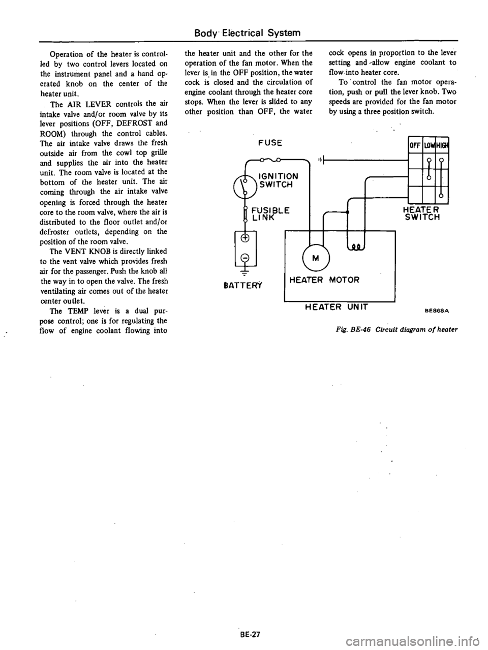
FUSE
IOfF
UlwlHI
ON
1
t
f
SWITCH
u
FUSI
BlE
rl
HEATE
R
LINK
SWITCH
is
G
luJ
BATTERY
HEATER
MOTOR
H
EATER
UN
IT
BE868A
Fig
BE
46
Circuit
diagram
of
heater
8E
27
Page 474 of 537
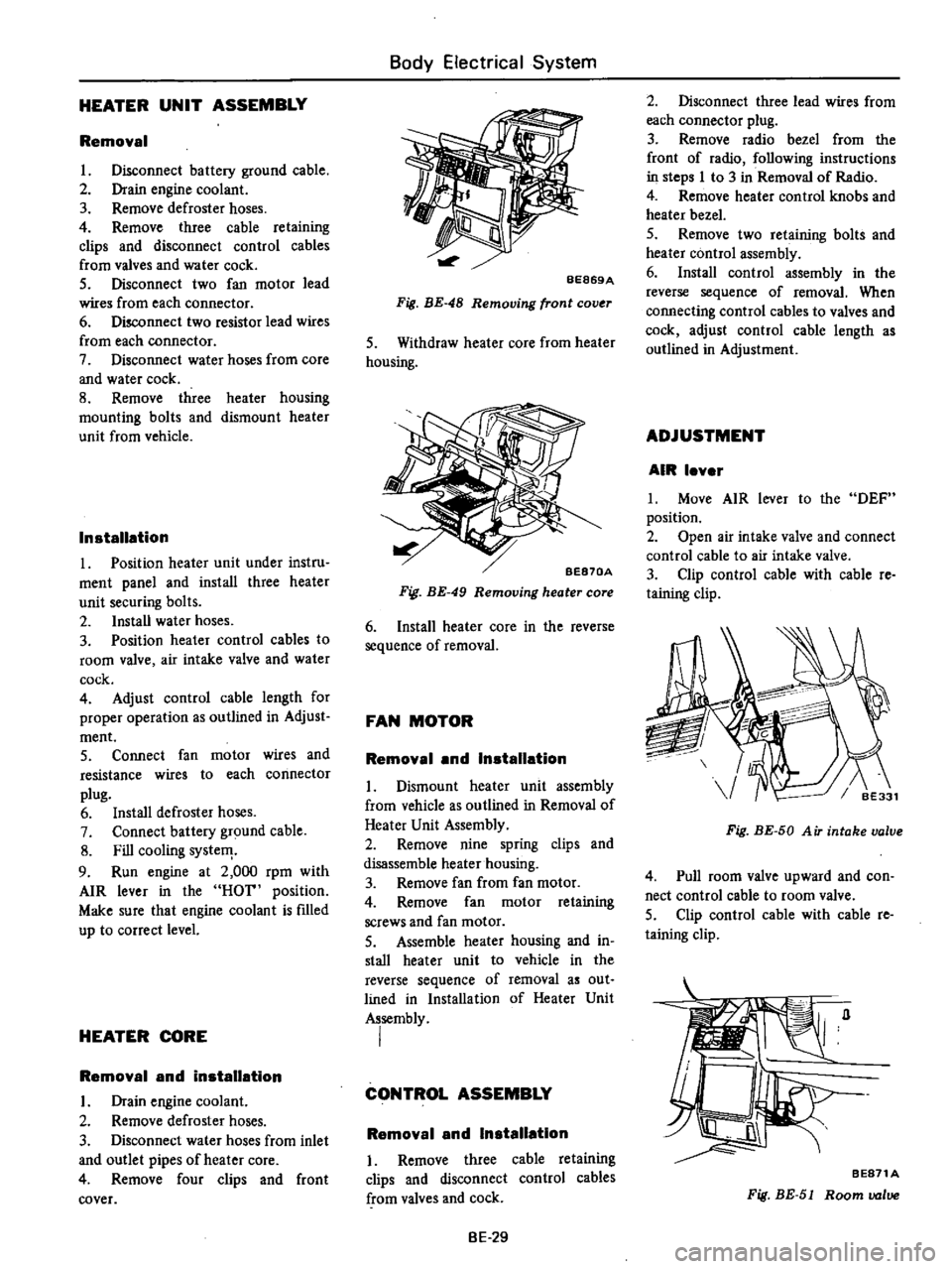
HEATER
UNIT
ASSEMBLY
Removal
L
Disconnect
battery
ground
cable
2
Drain
engine
coolant
3
Remove
defroster
hoses
4
Remove
three
cable
retaining
clips
and
disconnect
control
cables
from
valves
and
water
cock
5
Disconnect
two
fan
motor
lead
wires
from
each
connector
6
Disconnect
two
resistor
lead
wires
from
each
connector
7
Disconnect
water
hoses
from
core
and
water
cock
8
Remove
three
heater
housing
mounting
bolts
and
dismount
heater
unit
from
vehicle
Installation
1
Position
heater
unit
under
instru
ment
panel
and
install
three
heater
unit
securing
bolts
2
Install
water
hoses
3
Position
heater
control
cables
to
room
valve
air
intake
valve
and
water
cock
4
Adjust
control
cable
length
for
proper
operation
as
outlined
in
Adjust
ment
5
Connect
fan
motor
wires
and
resistance
wires
to
each
connector
plug
6
Install
defroster
hoses
7
Connect
battery
ground
cable
8
Fill
cooling
systeIT
9
Run
engine
at
2
000
rpm
with
AIR
lever
in
the
HOT
position
Make
sure
that
engine
coolant
is
fIlled
up
to
correct
level
HEATER
CORE
Removal
and
installation
L
Drain
engine
coolant
2
Remove
defroster
hoses
3
Disconnect
water
hoses
from
inlet
and
outlet
pipes
of
heater
core
4
Remove
four
clips
and
front
cover
Body
Electrical
System
BE869A
Fig
BE
48
Removing
front
cov
r
S
Withdraw
heater
core
from
heater
housing
BE870A
Fig
BE
49
Removing
heater
core
6
Install
heater
core
in
the
reverse
sequence
of
removal
FAN
MOTOR
Removal
and
Installation
L
Dismount
heater
unit
assembly
from
vehicle
as
outlined
in
Removal
of
Heater
Unit
Assembly
2
Remove
nine
spring
clips
and
disassemble
heater
housing
3
Remove
fan
from
fan
motor
4
Remove
fan
motor
retaining
screws
and
fan
motor
S
Assemble
heater
housing
and
in
stall
heater
unit
to
vehicle
in
the
reverse
sequence
of
removal
as
out
lined
in
Installation
of
Heater
Unit
Assembly
I
CONTROL
ASSEMBLY
Removal
and
Installation
I
Remove
three
cable
retaining
clips
and
disconnect
control
cables
from
valves
and
cock
BE
29
2
Disconnect
three
lead
wires
from
each
connector
plug
3
Remove
radio
bezel
from
the
front
of
radio
following
instructions
in
steps
I
to
3
in
Removal
of
Radio
4
Remove
heater
control
knobs
and
heater
bezel
5
Remove
two
retaining
bolts
and
heater
control
assembly
6
Install
control
assembly
in
the
reverse
sequence
of
removal
When
connecting
control
cables
to
valves
and
cock
adjust
control
cable
length
as
outlined
in
Adjustment
ADJUSTMENT
AIR
lever
L
Move
AIR
lever
to
the
DEF
position
2
Open
air
intake
valve
and
connect
control
cable
to
air
intake
valve
3
Clip
control
cable
with
cable
re
taining
clip
Fig
BE
50
A
iT
intake
valve
4
Pull
room
valve
upward
and
con
nect
control
cable
to
room
valve
5
Clip
control
cable
with
cable
re
taining
clip
BE871A
Fig
BE
51
Room
valve
Page 518 of 537
INSPECTION
Evaporator
Check
evaporator
for
leakage
or
damage
If
damaged
replace
Expansion
valve
Check
expansion
valve
for
leakage
or
clogging
If
clogged
clean
filter
in
expansion
valve
If
damaged
replace
RECEIVER
DRYER
AND
PIPING
REMOVAL
AND
INSTAUATION
Receiver
dryer
I
Disconnect
battery
ground
cable
2
Discharge
system
Refer
to
Dis
charging
System
under
General
Service
section
3
Disconnect
compressor
lead
wire
at
connector
4
Disconnect
cooling
pipes
at
joints
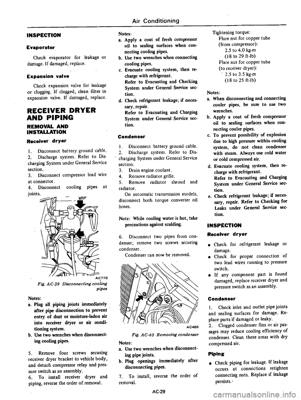
Acno
Fig
AC
39
Diaconnecting
coo
ing
pipes
Notes
a
Plug
all
piping
joints
immediately
after
pipe
disconnection
to
prevent
entry
of
dust
or
moisture
laden
air
into
receiver
dryer
or
air
aJOdi
tioning
system
b
Use
two
wrenches
when
dIsconnect
ing
cooling
pipes
5
Remove
four
screws
securing
receiver
dryer
bracket
to
vehicle
body
and
detach
compressor
relay
and
pres
sure
switch
as
an
assembly
6
To
install
receiver
dryer
and
piping
reverse
the
order
of
removal
Air
Conditioning
Notes
a
Apply
a
coat
of
fresh
compressor
oil
to
sealing
surfaces
when
con
necting
cooling
pipes
b
Use
two
wrenches
when
connecting
cooling
pipes
c
Evacuate
cooling
system
then
re
charge
with
refrigerant
Refer
to
Evacuating
and
Checking
System
under
General
Service
sec
tion
d
Check
refrigerant
leakage
if
neces
sary
repair
Refer
to
Evacuating
and
Charging
System
under
General
Service
See
tion
Condenser
Disconnect
battery
ground
cable
2
Discharge
system
Refer
to
Dis
charging
System
under
General
Service
section
3
Drain
engine
coolant
4
Remove
radiator
grille
5
Remove
radiator
shroud
and
radiator
On
automatic
transmission
models
disconnect
both
torque
converter
oil
hoses
Note
While
cooling
water
is
hot
take
precautions
against
scalding
6
Disconnect
two
pipes
from
con
denser
remove
two
screws
securing
condenser
Condenser
can
now
be
removed
AC485
Fig
AC
40
Removing
conden
er
Notes
a
Use
two
wrenches
when
disconnect
ing
pipe
joints
b
Plug
openings
immediately
after
disconnecting
pipes
7
To
install
reverse
the
order
of
removal
AC
29
Tightening
torque
Flare
nut
for
copper
tube
from
compressor
2
5
to
4
0
kg
m
i8
to
29
ft
Ib
Flare
nut
for
copper
tube
to
receiver
dryer
2
5
to
3
5
kg
m
i8
to
25
ft
lb
Notes
a
When
disconnecting
and
connecting
cooler
pipes
be
sure
to
use
two
wrenches
b
Apply
a
coat
of
fresh
compressor
oil
to
sealing
surfaces
when
con
necting
cooler
pipes
c
To
prevent
possibility
of
explosion
due
to
high
pressure
within
cooling
system
do
not
clean
condenser
with
steam
Always
use
cold
water
or
cold
compressed
air
d
Evacuate
cooling
system
then
re
charge
with
refrigerant
Refer
to
Evacuating
and
Charging
System
under
General
Service
sec
tion
e
Check
refrigerant
leakage
if
neces
sary
repair
Refer
to
Checking
for
Leaks
under
General
Service
sec
tion
INSPECTION
RecelYer
dryer
Check
for
refrigerant
leakage
or
damage
Check
for
proper
connection
of
two
lead
wires
running
to
pressure
switch
If
any
component
part
is
found
damaged
replace
receiver
dryer
and
pressure
switch
as
an
assembly
Condenser
I
Check
inlet
and
outlet
pipe
joints
and
sealing
surfaces
for
damage
Re
place
parts
if
damaged
or
leaky
2
Clogged
condenser
fins
or
air
pas
sages
may
reduce
cooling
efficiency
of
condenser
Clean
these
areas
with
dry
compressed
air
Piping
Check
piping
for
leakage
If
leakage
occurs
at
connections
retighten
connecting
nuts
Replace
if
leakage
persists