height DATSUN PICK-UP 1977 User Guide
[x] Cancel search | Manufacturer: DATSUN, Model Year: 1977, Model line: PICK-UP, Model: DATSUN PICK-UP 1977Pages: 537, PDF Size: 35.48 MB
Page 227 of 537
Stroke
30
mm
Jt
i
I
1
18
in
Sj
1
i
J
o
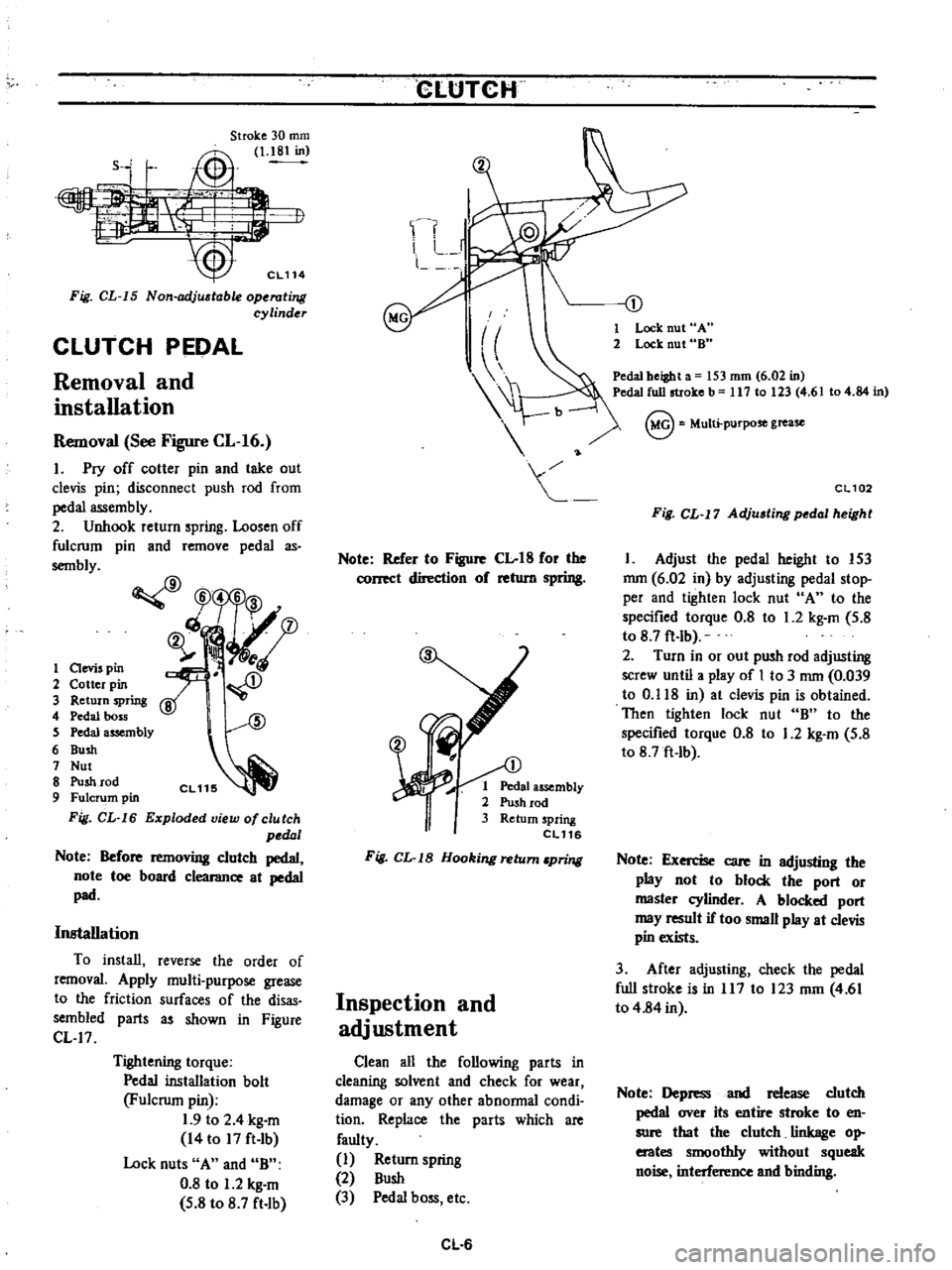
Fig
CL
15
Non
adj
table
operating
cylinder
CLUTCH
PEDAL
Removal
and
installation
Removal
See
Figure
CL
16
1
Pry
off
cotter
pin
and
take
out
clevis
pin
disconnect
push
rod
from
pedal
assembly
2
Unhook
return
spring
Loosen
off
fulcrum
pin
and
remove
pedal
as
sembly
CfJ
W5
6
3
ch
fD
ij
ll
i
A
1
aevis
pin
2
Cotter
pin
3
Return
spring
4
Pedal
boss
S
Pedal
assembly
6
Bush
7
Nut
8
Push
rod
9
Fulcrum
pin
Fig
CL
16
Exploded
view
of
clutch
pedal
Note
Before
removing
clutch
pedal
note
toe
board
clearance
at
pedal
pad
Installation
To
install
reverse
the
order
of
removal
Apply
multi
purpose
grease
to
the
friction
surfaces
of
the
disas
sembled
parts
as
shown
in
Figure
CL
17
Tightening
torque
Pedal
installation
bolt
Fulcrum
pin
1
9
to
2
4
kg
m
14
to
17
ft
Ib
Lock
nuts
A
and
B
0
8
to
1
2
kg
m
5
8
to
8
7
ft
lb
CLtJTCH
Note
Refer
to
Figure
Clot8
for
the
correct
direction
of
return
spring
1
Pedal
assembly
2
Push
rod
3
Return
spring
eL116
Fig
CL
1B
Hooking
return
pring
Inspection
and
adjustment
Clean
all
the
following
parts
in
cleaning
solvent
and
check
for
wear
damage
or
any
other
abnormal
condi
tion
Replace
the
parts
which
are
faulty
1
Return
spring
2
Bush
3
Pedal
boss
etc
CL
6
1
Lock
nut
A
2
Lock
nut
8
Pedal
beiBht
a
53
mm
6
02
in
Pedal
full
stroke
b
117
10
23
4
6
104
84
in
@
Multi
purpose
grease
CL102
Fig
CL
17
Adju
ting
pedal
height
1
Adjust
the
pedal
height
to
153
mm
6
02
in
by
adjusting
pedal
stop
per
and
tighten
lock
nut
A
to
the
specified
torque
0
8
to
1
2
kg
m
5
8
to
8
7
ft
lb
2
Turn
in
or
out
push
rod
adjusting
screw
until
a
play
of
I
to
3
mm
0
039
to
0
118
in
at
clevis
pin
is
obtained
Then
tighten
lock
nut
B
to
the
specified
torque
0
8
to
1
2
kg
m
5
8
to
8
7ft
Ib
Note
Exercise
care
in
adjusting
the
play
not
to
block
the
port
or
master
cylinder
A
blocked
port
may
result
if
too
small
play
at
clevis
pin
exists
3
After
adjusting
check
the
pedal
full
stroke
is
in
117
to
123
mm
4
61
to
4
84
in
Note
Depress
and
release
clutch
pedal
over
its
entire
stroke
to
en
sure
that
the
clutch
linkage
op
erates
smoothly
without
squeak
noise
interference
and
binding
Page 228 of 537
CLUTCH
CYLINDER
MASTER
Removal
and
installation
Removal
I
Remove
clcvis
pin
at
push
rod
2
Disconnect
clutch
tube
from
master
cylinder
and
drain
clutch
fluid
3
Remove
bolts
securing
master
Disassembly
and
assembly
CLUTCH
cylinder
to
the
vehicle
and
dismount
master
cylinder
Note
Remove
dust
cover
from
master
cylinder
body
on
the
side
of
driv
er
s
seat
Installation
To
install
reverse
the
order
of
removal
Closely
observe
the
following
instructions
1
Adjust
pedal
height
by
changing
pedal
stopper
length
Disassembly
1
Remove
dust
cover
and
remove
stopper
ring
from
body
2
Remove
push
rod
and
piston
as
sembly
3
Take
off
piston
cups
4
Remove
spiing
seat
from
piston
and
take
off
supply
valve
if
necessary
See
Figure
CL
19
Note
Discard
piston
cup
supply
valve
and
spring
seat
after
removal
Assembly
To
assemble
reverse
the
order
of
disassembly
Closely
observe
the
fol
lowing
instructions
I
Dip
piston
cup
in
brake
fluid
before
installing
Make
sure
that
it
is
correctly
faced
in
position
2
Apply
a
coating
of
brake
fluid
to
cylinder
and
piston
when
assembling
3
Press
piston
into
spring
seat
when
assembling
CL
7
2
Bleed
air
out
of
hydraulic
system
Tightening
torque
Master
cylinder
to
dash
panel
0
8
to
1
2
kg
m
5
8
to
8
7
ft
lb
Clutch
tube
connector
Flare
nut
1
5
to
1
8
kg
m
II
to
13
ft
lb
3
Using
Flare
Nut
Torque
Wrench
GG94310000
tighten
each
connector
to
the
specified
torque
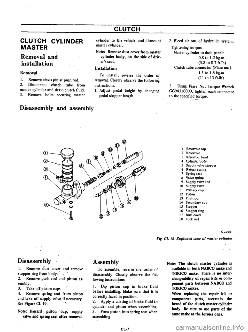
1
Reservoir
cap
2
Reservoir
3
Reservoir
band
4
Cylinder
body
5
Supply
valve
stopper
6
Return
spring
7
Spring
seat
8
Valve
spring
9
Supply
valve
rod
10
Supply
valve
11
Primary
cup
12
Piston
13
Push
rod
14
Secondary
cup
15
Stopper
16
Stopper
ring
17
DU5t
cover
18
Lock
nut
CL265
Fig
CL
19
Exploded
view
of
maater
cylinder
Note
The
clutch
master
cylinder
is
available
in
both
NABCO
make
and
TOKICO
make
There
is
no
inter
changeability
of
repair
kits
or
com
ponent
parts
between
NABCO
and
TOKlCO
makes
When
replacing
the
repair
kit
or
component
parts
ascertain
the
brand
of
the
clutch
IIIBSter
cylinder
body
Be
sure
to
use
parts
of
the
same
make
as
the
former
ones
Page 230 of 537
CLUTCH
SERVICE
DATA
AND
SPECIFICATIONS
Clutch
cover
Clu
tch
cover
type
Diaphragm
spring
to
flywheel
distance
Unevenness
of
diaphragm
spring
toe
height
Full
load
Out
of
flatness
of
pressure
plate
Allowable
refacing
limit
of
pressure
plate
Clutch
disc
Facing
size
Outer
dia
x
inside
dia
x
thickness
Thickness
of
disc
assembly
Free
Compressed
Number
of
torsion
springs
Allowable
minimum
depth
of
rivet
head
from
surface
Allowable
facing
run
out
Allowable
free
play
of
spline
at
the
outer
edge
of
disc
Clutch
pedal
Pedal
height
Play
at
clevis
pin
Full
stroke
Clutch
master
cylinder
Dia
of
master
cylinder
Allowable
maximum
clearance
between
cylinder
and
piston
Clutch
operating
cylinder
Dia
of
operating
cylinder
Tightening
torque
Clutch
assembly
to
flywheel
securing
bolt
Pedal
installation
bolt
Fulcrum
pin
Pedal
stopper
lock
nut
Push
rod
lock
nut
Master
cylinder
to
dash
panel
securing
bolt
Clutch
tube
connector
Flare
nut
Clutch
hose
connector
Operating
cylinder
to
clutch
housing
securing
bolt
Bleeder
screw
mm
in
mm
in
kg
Qb
mm
in
mm
in
Diaphragm
C225S
33
to
35
1
23
to
1
38
less
than
0
5
0
020
400
882
0
1
0
004
1
0
0
040
mm
in
225
x
150
x
3
5
8
86
x
5
91
x
0
138
mm
in
mm
in
8
3
to
8
9
0
327
to
0
350
7
6
to
8
0
0
299
to
0
315
6
0
3
0
012
0
5
0
020
0
4
0
016
mm
in
mm
in
mm
in
mm
in
153
6
02
mm
in
I
to
3
0
039
to
0
118
mm
in
117
to
123
4
61
to
4
84
mm
in
15
87
5
8
mm
in
0
15
0
0059
mm
in
19
05
Yo
kg
m
ft
lb
1
5
to
2
2
lito
16
kg
m
ft
Ib
1
9
to
2
4
14
to
17
kg
m
ft
b
0
8
to
1
2
5
8
to
8
7
kg
m
ft
lb
0
8
to
1
2
5
8
to
8
7
kg
m
ft
Ib
0
8
to
1
2
5
8
to
8
7
kg
m
ft
lb
1
5
to
1
8
11
to
13
kg
m
ft
lb
1
7
to
2
0
12
to
14
kg
m
ft
lb
2
5
to
3
5
18
to
25
kg
m
ft
Ib
0
7
to
0
9
5
1
to
6
5
CL
9
Page 231 of 537
CLUTCH
TROUBLE
DIAGNOSES
AND
CORRECTIONS
Condition
Probable
cause
and
testing
Clutch
slips
Corrective
action
Slipping
of
the
clutch
may
be
noticeable
when
any
of
the
following
symptoms
is
encountered
during
operation
I
Vehicle
will
not
respond
to
engine
speed
during
acceleration
2
Insufficient
vehicle
speed
3
Lack
of
power
during
uphill
driving
Some
of
the
above
conditions
are
also
experienced
when
engine
problem
is
oc
urring
First
de
tennine
whether
engine
or
clutch
is
causing
the
problem
If
slipping
clutch
is
left
unheeded
wear
and
or
overheating
will
occur
on
clutch
facing
until
it
is
no
longer
serviceable
TO
TEST
FOR
SLIPPING
CLlJfCH
proceed
as
follows
During
upgrade
travelling
run
engine
at
about
40
to
50
km
h
25
to
31
MPH
with
gear
shift
lever
in
3rd
speed
position
shift
into
highest
gear
and
at
the
same
time
rev
up
engine
If
clutch
is
slipping
vehicle
will
not
readily
respond
to
depression
of
accelerator
pedal
Clutch
facing
worn
excessively
Oil
or
grease
on
clutch
facing
W
r
d
clut
h
cov
r
pressure
plat
Replace
Replace
tpa
o
e
lace
Dragging
clutch
is
particularly
noticeable
when
shifting
gears
especially
into
low
gear
TO
TEST
FOR
DRAGGING
CLlJfCH
proceed
as
follows
I
Start
engine
Disengage
clutch
Shift
into
reverse
gear
and
then
into
Neutral
Gradually
increase
engine
speed
and
again
shift
into
reverse
gear
If
clutch
is
dragging
gear
grating
is
heard
when
shifting
from
Neutral
into
Reverse
Clutch
drags
2
Stop
engine
and
shift
gear
Conduct
this
test
at
each
gear
position
3
Gears
are
smoothly
shifted
in
step
2
but
drag
when
shifting
to
1st
speed
position
at
idling
a
If
dragging
is
encountered
at
the
end
of
shifting
check
condition
of
synchro
mechanism
in
transmission
b
If
dragging
is
encountered
at
the
beginning
of
shifting
proceed
to
step
4
below
4
Push
change
lever
toward
Reverse
side
depress
pedal
to
check
for
free
travel
a
If
pedal
can
be
depressed
further
check
clutch
condition
b
If
pedal
cannot
be
depressed
further
proceed
to
step
5
below
5
Check
clutch
control
pedal
height
pedal
free
travel
withdrawal
lever
play
etc
If
no
abnonnal
condition
exists
and
if
pedal
cannot
be
depressed
further
check
clutch
condition
Clutch
disc
runout
or
warped
Wear
or
rust
on
hub
splines
in
clutch
disc
Diaphragm
spring
toe
height
out
of
ad
justment
or
toe
tip
worn
Worn
or
improperly
installed
parts
CL10
Repair
or
replace
Clean
and
lubricate
with
grease
or
replace
Adjust
or
replace
Repair
or
replace
Page 232 of 537
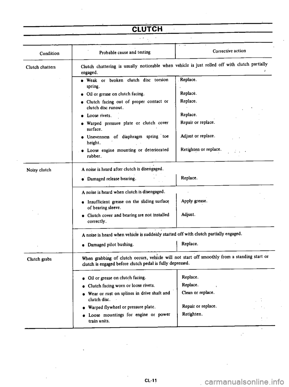
Condition
Clutch
chatters
Noisy
clutch
Clutch
grabs
CLUTCH
Probable
cause
and
testing
Corrective
action
Clutch
chattering
is
usually
noticeable
when
vchicle
is
just
rolled
off
with
clutch
partially
engaged
Weak
or
broken
clutch
disc
torsion
spring
Oil
or
grease
on
clutch
facing
Clutch
facing
out
of
proper
contact
or
clutch
disc
runout
Loose
rivets
Warped
pressure
plate
or
clutch
cover
surface
Unevenness
of
diaphragm
spring
toe
height
Loose
engine
mounting
or
deteriorated
rubber
A
noise
is
heard
after
clutch
is
disengaged
Damaged
release
bearing
A
noise
is
heard
when
clutch
is
disengaged
Insufficient
grease
on
the
sliding
surface
of
bearing
sleeve
Clutch
cover
and
bearing
are
not
installed
correctly
Replace
Replace
Replace
Replace
Repair
or
replace
Adjust
or
replace
Retighten
or
replace
I
Replace
Apply
grease
Adjust
A
noise
is
heard
when
vehicle
is
suddei11y
staited
off
with
clutch
partially
engaged
Damaged
pilot
bushing
I
Replace
When
grabbing
of
clutch
occurs
vehicle
will
not
start
off
smoothly
from
a
standing
start
or
clutch
is
engaged
before
clutch
pedal
is
fully
depressed
Oil
or
grease
on
clutch
facing
Clutch
facing
worn
or
loose
rivets
Wear
or
rust
on
splines
in
drive
shaft
and
clu
tch
disc
Warped
flywheel
or
pressure
plate
Loose
mountings
for
engine
or
power
train
units
CLll
Replace
Replace
Clean
or
replace
Repair
or
replace
Retighten
Page 292 of 537
2
RANGE
2ND
GEAR
Automatic
Transmission
In
2
range
the
gear
rario
is
IOI
keJ
III
the
2nd
forward
speed
In
this
case
the
rear
dutch
is
engaged
and
the
band
brake
holds
the
front
clutch
drum
the
connecting
shell
and
sun
gear
from
rotating
The
power
flow
takes
place
through
the
input
shaft
inlo
the
rear
clutch
and
the
front
internal
gear
With
Ihe
sun
gear
held
stationary
the
front
planetary
gears
rotate
around
the
sun
gear
carrying
the
front
planet
carrier
with
them
The
front
planet
carrier
being
splined
to
the
output
shaft
causes
clockwise
rotation
of
the
OUI
put
shaft
at
a
reduced
speed
compared
to
the
speed
of
the
input
shaft
with
an
increase
in
torque
As
the
low
and
reverse
brake
is
not
engaged
the
clock
wise
rotation
of
the
output
shaft
causes
clockwise
rotation
of
fear
inter
nal
gear
and
the
rear
planet
carrier
also
rotates
around
the
sun
gear
in
a
clockwise
direction
The
one
way
clutch
will
act
to
allow
clockwise
rotation
of
connecting
drum
When
the
manual
valve
V
is
posi
tioned
at
2
the
line
pressure
7
is
introduced
into
the
line
pressure
cir
cuits
I
2
and
4
The
line
pressure
I
is
led
to
the
governor
rear
clutch
and
I
st
2nd
shift
valve
CID
as
in
the
case
of
D
range
The
line
pressure
2
locks
the
second
lock
valve
@and
is
led
to
thc
tightening
side
of
Ihe
band
servo
The
2nd
gear
is
therefore
fixed
regardless
of
vehicle
speed
When
DJ
range
3rd
gear
is
shifted
to
2
range
the
line
pressure
4
enters
Ihe
throttle
back
up
valve
V
and
produces
a
high
pressure
in
the
circuit
17
increasing
thc
throttle
pressure
li
6
The
line
pressure
7
is
therefore
increased
and
quickly
tightens
the
band
N
e
DJ
range
3rd
gear
to
2
range
If
DJ
range
3rd
gear
is
shifled
to
2
range
during
operation
the
manual
valve
V
is
also
shifted
to
A
T078
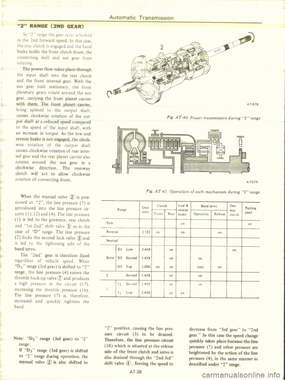
Fig
AT
40
Powu
tTansminion
during
2
H
range
A
1079
Fig
AT
41
Operation
of
each
mechanism
during
2
range
Clutch
Low
Band
ser
o
On
Parking
Gw
Ran8t
utio
w
pa
Front
Rear
brake
Operalion
Release
dutch
Pui
on
on
Revtrs
e
2
182
on
on
on
Neutral
01
Low
2
458
on
on
Drive
02
Second
1
458
Oft
Oft
OJ
Top
1
000
on
on
on
on
1
Second
1
458
on
Oft
12
tocond
1458
on
on
J
tt
Low
2
458
on
on
2
position
causing
the
line
pres
sure
circuit
3
to
be
drained
Therefore
the
line
pressure
circuit
10
which
is
situated
at
the
release
side
of
the
front
clutch
and
servo
is
also
drained
through
the
2nd
3rd
shift
val
e
@
forcing
the
speed
to
AT
28
decrease
from
3rd
gear
to
2nd
gear
In
this
case
the
speed
change
quickly
takes
place
because
the
line
pressure
7
and
other
pressure
are
heightened
by
the
action
of
the
line
pressure
4
in
the
same
manner
as
described
under
2
range
Page 333 of 537
PROPELLER
SHAFT
DIFFERENTIAL
CARRIER
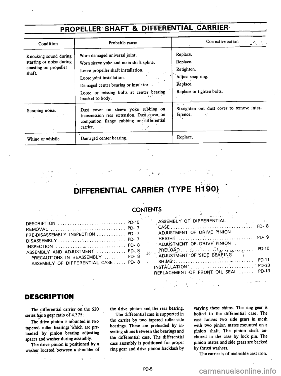
Condition
Probable
cause
Knocking
sound
during
starting
or
noise
during
coasting
on
propeller
shaft
Worn
damaged
universal
joint
Worn
sleeve
yoke
and
main
shaft
spline
Loose
propeller
shaft
installation
Loose
joint
installation
Damaged
center
bearing
or
insulator
Loose
or
missing
bolts
at
center
bearing
bracket
to
body
Scraping
noise
Dust
cover
on
sleeve
yoke
rubbing
on
transmission
rear
extension
Dust
c
ver
on
companion
flange
rubbing
on
differ
mtial
carrier
Whine
or
whistle
Damaged
center
bearing
Corrective
action
Replace
Replace
Retighten
Adjust
snap
ring
Replace
Replace
or
tighten
bolts
Straighten
out
dust
cover
to
remove
inter
ference
Replace
DIFFERENTIAL
CARRIER
TYPE
H190
CONTENTS
DESCRIPTION
REMOVAL
PRE
DISASSEMBLY
INSPECTION
DISASSEMBLY
INSPECTION
ASSEMBLY
AND
ADJUSTMENT
PRECAUTIONS
IN
REASSEMBLY
ASSEMBLY
OF
DIFFERENTIAL
CASE
PD
5
PD
7
PD
7
PD
7
PD
8
PD
PD
8
PD
8
DESCRIPTION
The
differential
carrier
on
the
620
series
has
a
gear
ratio
of
4
37S
The
drive
pinion
is
rnounted
in
two
tapered
roUer
bearings
which
are
pre
loaded
by
pinion
bearing
adjusting
spacer
and
washer
during
assembly
The
drive
pinion
is
positioned
by
a
washer
located
between
a
shoulder
of
ASSEMBl
Y
OF
DIFFERENT
Al
CASE
ADJUSTMENT
OF
DRIVE
PINION
HEIGHT
ADJUSTME
NT
OF
DRIVE
PINION
PRELOAD
t
ADJUST
ENT
OF
SIDE
8EARING
SHIMS
INSTAllATION
REPLACEME
NTOF
FRONT
Oil
SEAL
the
drive
pinion
and
the
rear
bearing
The
differential
case
is
supported
in
the
carrier
by
two
tapered
roller
side
bearings
These
are
preloaded
by
in
serting
shims
between
the
bearings
and
the
differential
case
The
differential
case
assembly
is
positioned
for
proper
ring
gear
and
drive
pinion
backlash
by
PO
5
PD
8
PD
9
PD
lO
PD
11
PD
13
PD
13
varying
these
shims
The
ring
gear
is
bolted
to
the
differential
case
The
case
houses
two
side
gears
in
mesh
with
two
pinion
mates
mounted
on
a
pinion
shaft
The
pinion
shaft
an
chored
in
the
case
by
lock
pin
The
pinion
mates
and
side
gears
are
backed
by
thrust
washers
The
carrier
is
of
malleable
cast
iron
Page 337 of 537
PROPELLER
SHAFT
DifFERENTIAL
CARRIER
Standard
gauge
I
1
Fig
PD
14
Me
uring
bearing
width
8
Press
fit
side
bearing
cone
into
differential
case
using
Differential
Side
Bearing
Drift
ST33230000
and
Adapt
er
ST33061000
t
J
I
ST33230000
io
o1
P0244
Fig
PD
15
ln
talling
side
bearing
cone
ADJUSTMENT
OF
DRIVE
PINION
HEIGHT
Adjust
the
pinion
height
with
washer
provided
between
rear
bearing
inner
race
a
ld
the
back
of
pinion
gear
Press
fit
front
and
rear
bearing
outer
races
into
gear
carrier
using
Drive
Pinion
Ou
ter
Race
Drift
Front
ST306
I
1000
and
Sf30613oo0
Rear
ST306
II
000
and
ST3062I
000
2
Fit
rear
bearing
on
carrier
and
install
Dummy
Shaft
Sf3
I
942000
and
Collar
ST3197oo00
on
rear
bearing
and
place
H
eight
Gauge
ST31941000
on
carrier
ST31941000
PD2
b
Fig
PD
16
Adjusting
pinion
height
3
Measure
the
clearance
N
be
tween
the
tip
end
of
height
gauge
and
the
end
surface
of
dummy
shaft
using
a
thickness
gauge
P0235
Fig
PD
17
Measuring
clearance
4
Tlie
thickness
of
drive
pInIOn
height
adjusting
wa
sh
ers
can
be
ob
tained
from
the
following
formula
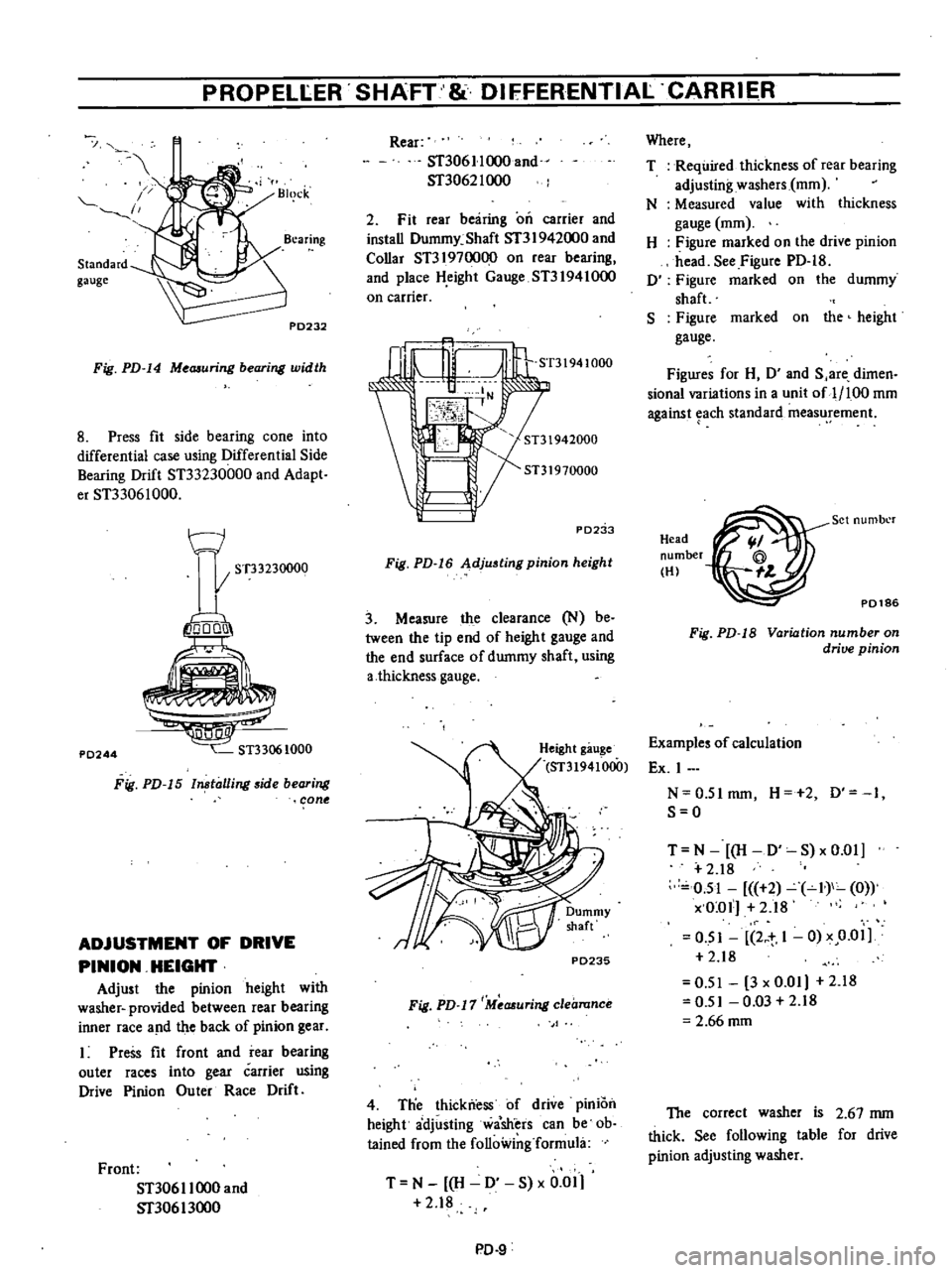
T
N
H
0
S
x
0
01
2
18
PD
9
Where
T
Required
thickness
of
rear
bearing
adjusting
washers
mOl
N
Measured
value
with
thickness
gauge
mOl
H
Figure
marked
on
the
drive
pinion
head
See
Figure
PD
18
0
Figure
marked
on
the
dummy
shaft
S
Figure
marked
on
the
height
gauge
Figures
for
H
0
and
S
are
dimen
sional
variations
in
a
unit
of
1
100
mOl
against
each
standard
measurement
Head
number
HI
P0186
Set
numbl
r
Fig
PD
18
Variation
number
on
drive
pinion
Examples
of
calculation
Ex
I
N
0
5Imm
H
2
0
1
S
O
T
N
H
D
S
xO
01
2
18
0
51
2
I
0
x
O
ol
2
18
O
SI
2
t
1
0
x
0
01
2
18
0
51
3
x
0
01
2
18
0
51
0
03
2
18
2
66
mOl
The
correct
washer
is
2
67
mm
thick
See
following
table
for
drive
pinion
adjusting
washer
Page 340 of 537
PROPELLER
SHAFf
DIFFERENTIAL
CARR
IER
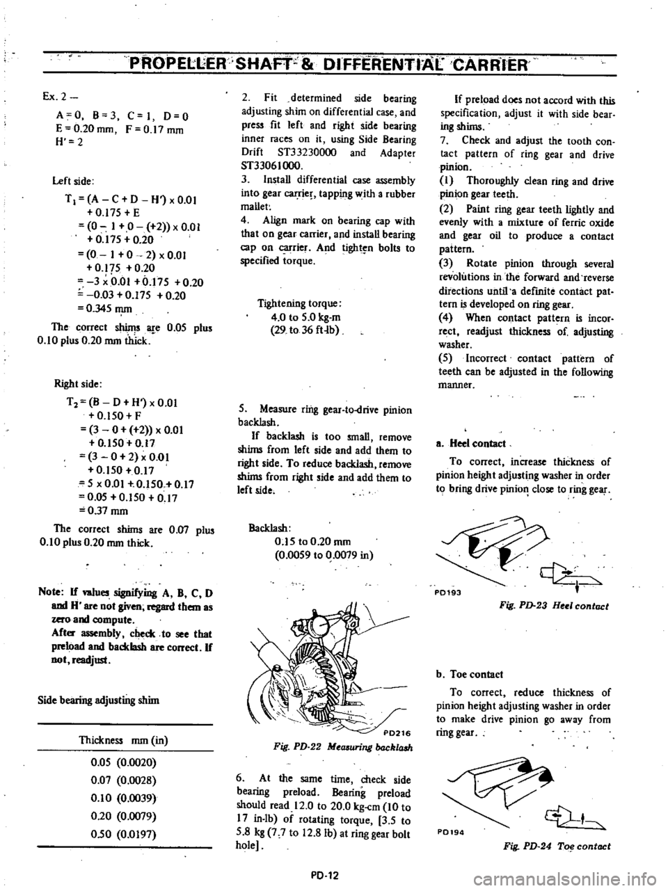
Ex
2
A
0
B
3
C
I
0
0
E
0
20
mOl
F
0
17
mOl
H
2
Left
side
T
I
A
C
D
H
x
om
0
17S
E
0
I
0
2
x
0
01
0
I7S
0
20
0
I
0
2
x
0
01
0
17S
0
20
3
Om
0
17S
0
20
0
03
0
17S
0
20
O
34S
mrn
The
correct
shinjs
are
O
OS
plus
0
10
plus
0
20
mrn
thick
Right
side
T2
B
D
H
xO
0l
O
ISO
F
3
0
2
x
om
O
ISO
0
17
3
0
2
x
om
0
150
0
17
S
x
0
01
0
ISO
0
I7
O
OS
0
1S0
0
17
0
37
mrn
The
correct
shims
are
0
07
plus
0
1
0
plus
0
20
mm
thick
Note
If
w1ues
signifying
A
B
C
0
and
H
are
not
given
regard
them
as
zero
and
compute
Aft
assembly
check
to
see
that
preload
and
backlash
are
correct
If
not
readjust
Side
bearing
adjusting
shim
Thickness
mm
in
O
OS
0
0020
0
07
0
0028
0
1
0
0
0039
0
20
0
0079
0
50
0
0197
2
Fit
determined
side
bearing
adjusting
shim
on
differential
case
and
press
fit
left
and
right
side
bearing
inner
races
on
it
using
Side
Bearing
Drift
ST33230000
and
Adapter
ST33061000
3
Install
differential
case
assembly
into
gear
carrie
tapping
with
a
rubber
mallet
4
Align
mark
on
bearing
cap
with
that
on
gear
carrier
and
install
bearing
cap
on
carrier
And
tight
n
bolts
to
specified
torque
Tightening
torque
4
0
to
S
O
kg
m
29
to
36
fHb
S
Measure
ring
gear
to
drive
pinion
backlash
If
backlash
is
too
small
remove
shims
from
left
side
and
add
them
to
right
side
To
reduce
backlash
remove
shims
from
right
side
and
add
them
to
left
side
Backlash
O
1S
to
0
20
mrn
0
00S9
to
0
0079
in
Fig
PD
22
Mccuuring
back1aah
6
At
the
same
time
check
side
bearing
preload
Bearing
preload
should
read
12
0
to
20
0
kg
cm
10
to
17
in
lb
of
rotating
torque
3
S
to
S
8
kg
7
7
to
12
8
Ib
at
ring
gear
bolt
hole
PD
12
If
preload
does
not
accord
with
this
specification
adjust
it
with
side
bear
ing
shims
7
Check
and
adjust
the
tooth
con
tact
pattern
of
ring
gear
and
drive
pinion
I
Thoroughly
clean
ring
and
drive
pinion
gear
teeth
2
Paint
ring
gear
teeth
lightly
and
evenly
with
a
mixture
of
ferric
oxide
and
gear
oil
to
produce
a
contact
pattern
3
Rotate
pinion
through
several
revolutions
in
the
forward
and
reverse
directions
until
a
defmite
contact
pat
tern
is
developed
on
ring
gear
4
When
contact
pattern
is
incor
rect
readjust
thickness
of
adjusting
washer
S
Incorrect
contact
pattern
of
teeth
can
be
adjusted
in
the
following
manner
a
Heel
contact
To
correct
increase
thickness
of
pinion
height
adjusting
washer
in
order
to
bring
drive
pinio
close
to
ring
gear
P0193
Fig
PD
23
Hul
contact
b
Toe
contact
To
correct
reduce
thickness
of
pinion
height
adjusting
washer
in
order
to
make
drive
pinion
go
away
from
ring
gear
P0194
1
Fig
PD
24
To
contact
Page 347 of 537
PROPELLER
SHAFT
8i
DIFFERENTIALCARRIER
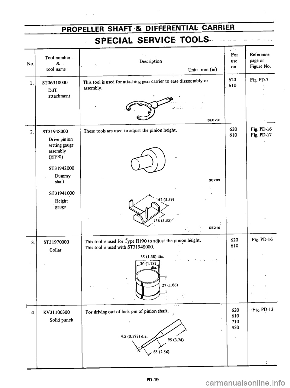
SPECIAL
SERVICE
TOOlS
No
Tool
number
tool
name
I
ST063
10000
Diff
attachment
2
ST3I
94S000
Drive
pinion
setting
gauge
assembly
H190
ST31942000
Dummy
shaft
ST31941000
Height
gauge
3
ST31970000
Collar
4
KV311
00300
Solid
punch
Description
Unit
mOl
in
This
tool
is
used
for
attaching
gear
carrier
to
ease
disassembly
or
assembly
SE023
These
tools
are
used
to
adjust
the
pinion
height
@
SE209
SE210
This
tool
is
used
for
Type
H
190
to
adjust
the
pinion
height
This
tool
is
used
with
ST3I
94S000
35
1
38
di
30
1
18
dia
1
27
1
06
l
For
driving
out
oflock
pin
of
pinion
shaft
4
5
0
177
di
Y
95
3
74
65
2
56
PD
19
For
use
on
620
610
620
610
620
610
620
610
710
S30
Reference
page
or
Figure
No
Fig
PD
7
Fig
PD
16
Fig
PD
17
Fig
PD
16
Fig
PI
13