height DATSUN PICK-UP 1977 Service Manual
[x] Cancel search | Manufacturer: DATSUN, Model Year: 1977, Model line: PICK-UP, Model: DATSUN PICK-UP 1977Pages: 537, PDF Size: 35.48 MB
Page 9 of 537
Fig
GI
9
Manual
trammiuion
number
location
Automatic
transmission
number
The
transmission
serial
number
is
attached
to
the
right
hand
side
of
transmission
case
Numbering
system
X
XXXXX
I
Serial
number
monthly
Month
of
manufacture
I
2
9
X
Y
Z
last
figure
of
year
of
manufacture
AT344
Fig
01
10
Automatic
trammi
sion
number
location
LIFTING
POINTS
AND
TOWING
LIFTING
POINTS
Screw
jack
Before
using
the
jack
proceed
a
follows
Generallnforml
ition
Apply
parking
brake
firmly
and
block
rear
wheels
if
the
front
of
the
vehicle
is
to
be
raised
Notes
a
Never
get
under
the
vehicle
while
it
is
supported
only
by
the
jack
Always
use
safety
stands
to
support
frame
or
rear
axle
case
when
you
have
to
get
beneath
the
vehicle
b
In
no
event
should
the
jack
be
applied
to
any
points
except
the
following
specified
portions
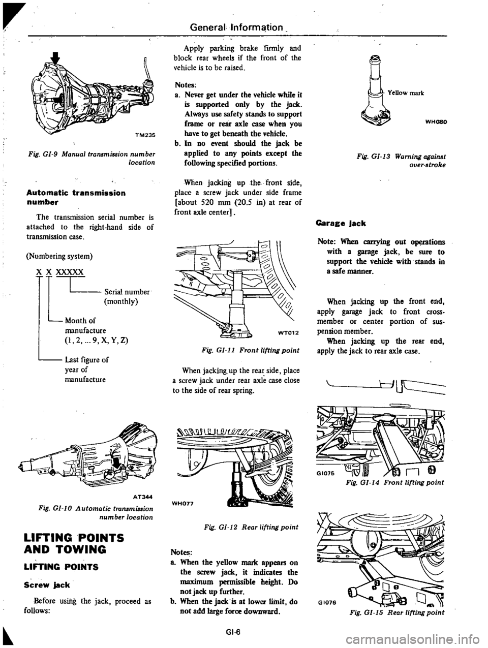
When
jacking
up
the
front
side
place
a
screw
jack
under
side
frame
about
520
nun
20
5
in
at
rear
of
front
axle
center
WT012
Fig
GI
ll
Front
lifting
point
When
jacking
up
the
rear
side
place
a
screw
jack
under
rear
axle
case
close
to
the
side
of
rear
spring
WH077
Fig
GI
12
Reor
lifting
point
Notes
a
When
the
yellow
mark
appean
on
the
screw
jack
it
indicates
the
maximum
permissible
height
Do
not
jack
up
further
b
When
the
jack
is
at
lower
llinit
do
not
add
large
force
downward
GI
6
YeDow
mark
WHOSO
Fig
GI
13
Warning
ogai
t
over
stroke
Garage
Jack
Note
When
carrying
out
operntions
with
a
garage
jack
be
sure
to
support
the
vehicle
withstands
in
a
safe
manner
When
jacking
up
the
front
end
apply
garage
jack
to
front
cross
member
or
center
portion
of
sus
pension
member
When
jacking
up
the
rear
end
apply
the
jack
to
rear
axle
case
r
J
uc
I
GI075
n9
Fig
GI
14
Front
lifting
point
GI076
Fig
GI
15
Rear
lifting
point
Page 34 of 537
r
EC350
Fig
ET
43
Cleanill
l
E
G
R
control
lJ
Jlue
Thermal
VBCuum
valve
Dismount
thermal
vacuum
valve
from
engine
Note
Before
dismounting
drain
e
gine
coolant
from
engine
Apply
vacuum
to
thermal
vacuum
valve
and
check
to
be
sure
that
ther
mal
vacuum
valve
opens
or
closes
in
response
to
engine
coolant
tempera
lurt
i1
i
iYCl
lt
lt
U
Thermal
vacuum
valve
should
open
at
a
temperature
of
57
to
630C
134
to
1450F
completing
the
vacuum
passage
Note
Do
not
aUow
water
to
get
inside
the
thermal
vacuum
valve
EC
242
Fig
ET
44
Checkill
lthermallXlCuum
valve
Engine
Tune
up
CHECKING
EVAPORATIVE
EMISSION
CONTROL
SYSTEM
Vapor
Rnes
and
fuel
vepor
control
valve
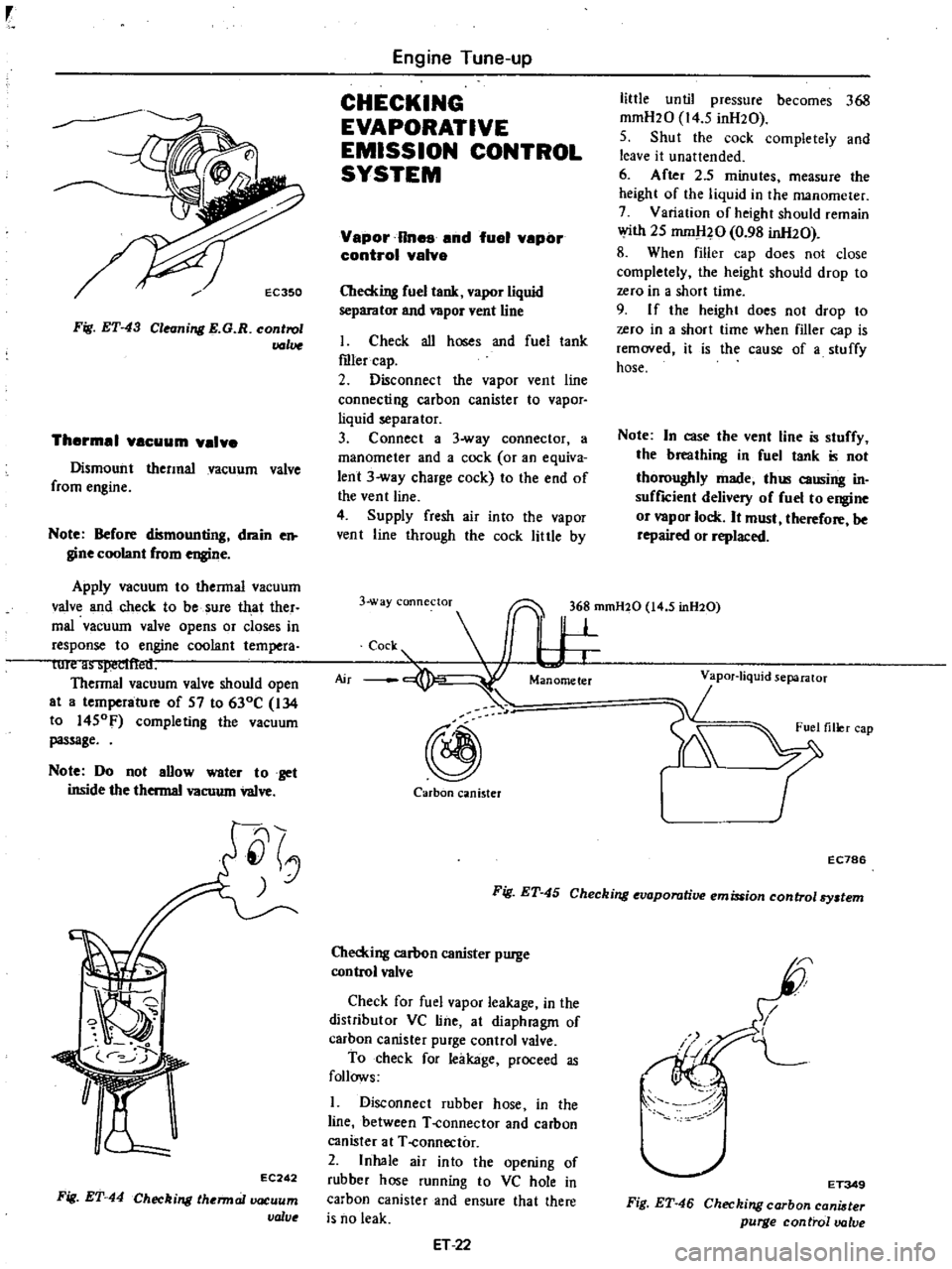
Checking
fuel
tank
vapor
liquid
separator
and
vapor
vent
line
I
Check
all
hoses
and
fuel
tank
roler
cap
2
Disconnect
the
vapor
vent
line
connecting
carbon
canister
to
vapor
liquid
separator
3
Connect
a
3
way
connector
a
manometer
and
a
cock
or
an
equiva
lent
3
way
charge
cock
to
the
end
of
the
vent
line
4
Supply
fresh
air
into
the
vapor
vent
line
through
the
cock
little
by
little
until
pressure
becomes
368
mmH20
14
5
inH20
5
Shut
the
cock
completely
and
leave
it
unattended
6
After
2
5
minutes
measure
the
height
of
the
liquid
in
the
manometer
7
Variation
of
height
should
remain
with
25
mm
l20
0
98
inH20
8
When
filler
cap
does
not
close
completely
the
height
should
drop
to
zero
in
a
short
time
9
I
f
the
height
does
not
drop
to
zero
in
a
short
time
when
filler
cap
is
removed
it
is
the
cause
of
a
stuffy
hose
Note
In
case
the
vent
line
is
stuffy
the
breathing
in
fuel
tank
is
not
thoroughly
made
thl
causing
in
suffICient
delivery
of
fuel
to
engine
or
vapor
lock
It
must
therefore
be
repaired
or
replaced
3
way
connectoT
36
mmH20
14
5
inH20
c
s
I
W
@
Carbon
canister
r
EC786
Fig
ET
45
Checking
evaporative
emission
control
By
tem
Checking
carbon
canister
purge
control
valve
Check
for
fuel
vapor
leakage
in
the
distributor
VC
line
at
diaphragm
of
carhon
canister
purge
control
valve
To
check
for
leakage
proceed
as
follows
1
Disconnect
rubber
hose
in
the
line
between
T
connector
and
carbon
canister
at
T
connector
2
Inhale
air
into
the
opening
of
rubber
hose
running
to
VC
hole
in
carbon
canister
and
ensure
that
there
is
no
leak
ET
22
I
I
L
I
ET349
Fig
ET
46
Checking
carbon
cani
ter
purge
control
valve
Page 54 of 537
Engine
Mechanical
Valve
head
diameter
I
In
42
0
to
42
2
1
654
to
1
661
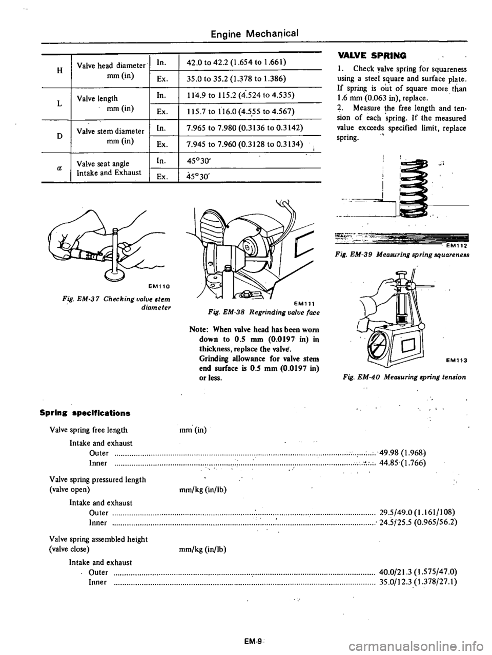
VALVE
SPRING
H
1
Check
valve
spring
for
squareness
mm
in
Ex
35
0
to
35
2
1
378
to
1
386
using
a
steel
square
and
surface
plate
In
114
9
to
115
2
4
524
to
4
535
If
spring
is
out
of
square
more
than
Valve
length
1
6
mm
0
063
in
replace
L
mm
in
2
Measure
lhe
free
length
and
ten
Ex
1157
to
116
0
4
555
to
4
567
sion
of
each
spring
If
the
measured
Valve
stem
diameter
In
7
965
to
7
980
0
3136
to
0
3142
value
exceeds
specified
limit
replace
D
mm
in
spring
Ex
7
945
to
7
960
0
3128
to
0
3134
Valve
seat
angle
In
45030
a
Intake
and
Exhaust
Ex
45030
EM110
Fig
EM
37
Checking
valve
tern
diameter
Spring
specifications
Valve
spring
free
length
Intake
and
exhaust
Outer
Inner
Valve
spring
pressured
length
valve
open
Intake
and
exhaust
Outer
Inner
Valve
spring
assembled
height
valve
close
Intake
and
exhaust
Outer
Inner
EMll1
Fig
EM
38
Regrinding
valve
face
Note
When
valve
head
has
been
worn
down
to
0
5
nun
0
0197
in
in
thickness
replace
the
valve
Grinding
allowance
for
valve
stem
end
surface
is
0
5
mm
0
0197
in
or
less
mm
in
mmlkg
in
lb
mmlkg
in
lb
EM
9
I
i
J
T
EM112
Fig
EM
39
Measuring
spring
quareneu
1
EM113
Fig
EM
40
Measuring
apring
ten
ion
49
98
1
968
44
85
1
766
29
5
49
0
1
161
108
24
5
25
5
0
965156
2
40
0
21
3
1
575
47
0
35
0
12
3
1
378
27
I
Page 58 of 537
Standard
Camshaft
bend
mm
in
0
02
0
0008
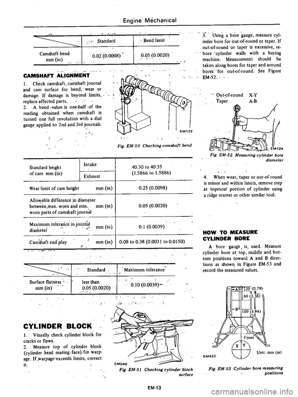
CAMSHAFT
ALIGNMENT
I
Check
camshaft
camshaft
journal
and
earn
surface
for
bend
wear
or
damage
If
damage
is
beyond
limits
replace
affected
parts
2
A
bend
value
is
one
half
of
the
reading
obtained
when
camshaft
is
turned
one
full
revolution
with
a
dial
gauge
applied
to
2nd
and
3rd
journals
Standard
height
of
tam
mm
in
I
Intake
1
Exhaust
Wear
limit
of
earn
height
mm
in
Allo
able
difference
in
diam
ter
betweim
max
worn
and
min
mm
in
worn
parts
of
c
mshaft
journal
Engine
Mechanical
Bend
limit
0
05
0
0020
I
Fig
EM
50
Checking
camMa
t
bend
40
30
to
40
35
1
5866
to
1
5886
0
25
0
0098
0
05
0
0020
Maximum
tolerance
in
j01
irri
mm
in
0
1
0
0039
diameter
CamShaft
end
play
mm
in
0
08
to
0
38
0
0031
to
0
0150
Standard
Surface
flatness
mm
in
less
than
0
05
0
0020
Cy
LlNDER
BLOCK
I
Visually
check
cylinder
block
for
cracks
or
flaws
2
Measure
top
of
cylinder
block
cylinder
head
mating
face
for
warp
age
If
warpage
exceeds
limits
correct
it
Maximum
tolerance
0
10
0
0039
EM540
Fig
EM
51
Cheching
cylinder
block
au
rface
EM
13
j
Using
a
bore
gauge
measure
cyl
inder
bore
for
out
of
round
or
taper
If
out
of
round
or
taper
is
excessive
re
bore
cylinder
walls
with
a
boring
machine
Measuremen
t
should
be
taken
along
bores
for
taper
and
around
bores
for
out
of
round
See
Figure
EM
52
Qu
t
of
round
Taper
X
Y
A
B
M12
Fig
EM
52
Measuring
cylinder
bore
diameter
4
When
wear
taper
or
out
of
round
is
minor
and
within
limits
remove
step
at
topmost
portion
of
cylinder
using
a
ridge
reamer
or
other
similar
tool
HOW
TO
MEASURE
CYLINDER
BORE
A
bore
gauge
is
used
Measure
cylind
r
bore
at
top
middle
and
bot
tom
positions
toward
A
and
B
direc
tions
as
shown
in
Figure
EM
53
and
record
the
measured
values
A
I
120
0
79
IlL
60
2
36
lll
B
100
3
94
el
1
Unit
mm
m
EM
22
r
Fig
EM
53
Cylinder
bort
me08Uring
positions
Page 62 of 537
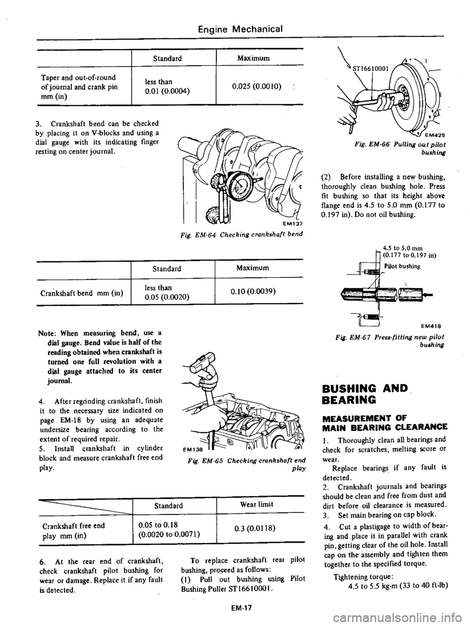
Standard
Taper
and
out
of
round
of
journal
and
crank
pin
mm
in
less
than
0
01
0
0004
3
Crankshaft
bend
can
be
checked
by
placing
it
on
V
blocks
and
using
a
dial
gauge
with
its
indicating
finger
resting
on
center
journal
Standard
Crankshaft
bend
mm
in
less
than
0
05
0
0020
Note
When
measuring
bend
use
a
dial
gauge
Bend
value
is
half
of
the
reading
obtained
when
crankshaft
is
turned
one
full
revolution
with
a
dial
gauge
attached
to
its
center
journal
4
After
regrinding
crankshaft
finish
it
to
the
necessary
size
indicated
on
page
EM
18
by
using
an
adequate
undersize
bearing
according
to
the
extent
of
required
repair
5
Install
crankshaft
in
cylinder
block
and
measure
crankshaft
free
end
play
Engine
Mechanical
Maximum
0
Q25
0
0010
EM137
Fig
EM
64
Checking
crankshaft
bend
Maximum
0
10
0
0039
Fig
EM
65
Checking
crankshaft
end
play
Standard
Wear
limit
Crankshaft
free
end
play
mm
in
0
05
to
0
18
0
0020
to
0
0071
0
3
0
0118
6
At
the
rear
end
of
crankshaft
check
crankshaft
pilot
bushing
for
wear
or
damage
Replace
it
if
any
fault
is
detected
To
replace
crankshaft
rear
pilot
bushing
pro
ceed
as
follows
I
Pull
out
bushing
using
Pilot
Bushing
Puller
STl66
1000
I
EM
17
STl6610001
EM425
Fig
EM
66
Pulling
out
pilot
bushing
2
Before
installing
a
new
bushing
thoroughly
clean
bushing
hole
Press
fit
bushing
so
that
its
height
above
flange
end
is
4
5
to
5
0
mm
0
177
to
0
197
in
Do
not
oil
bushing
EM418
Fig
EM
67
Press
fitting
new
pilot
bush
ng
BUSHING
AND
BEARING
MEASUREMENT
OF
MAIN
BEARING
CLEARANCE
I
Thoroughly
clean
all
bearings
and
check
for
scratches
melting
score
or
wear
Replace
bearings
if
any
fault
is
detected
2
Crankshaft
journals
and
bearings
should
be
clean
and
free
from
dust
and
dirt
before
oil
clearance
is
measured
3
Set
main
bearing
on
cap
block
4
Cut
a
plastigage
to
width
of
bear
ing
and
place
it
in
parallel
with
crank
pin
getting
clear
of
the
oil
hole
Install
cap
on
the
assembly
and
tighten
them
together
to
the
specified
torque
Tightening
torque
4
5
to
5
5
kg
m
33
to
40
ft
lb
Page 69 of 537
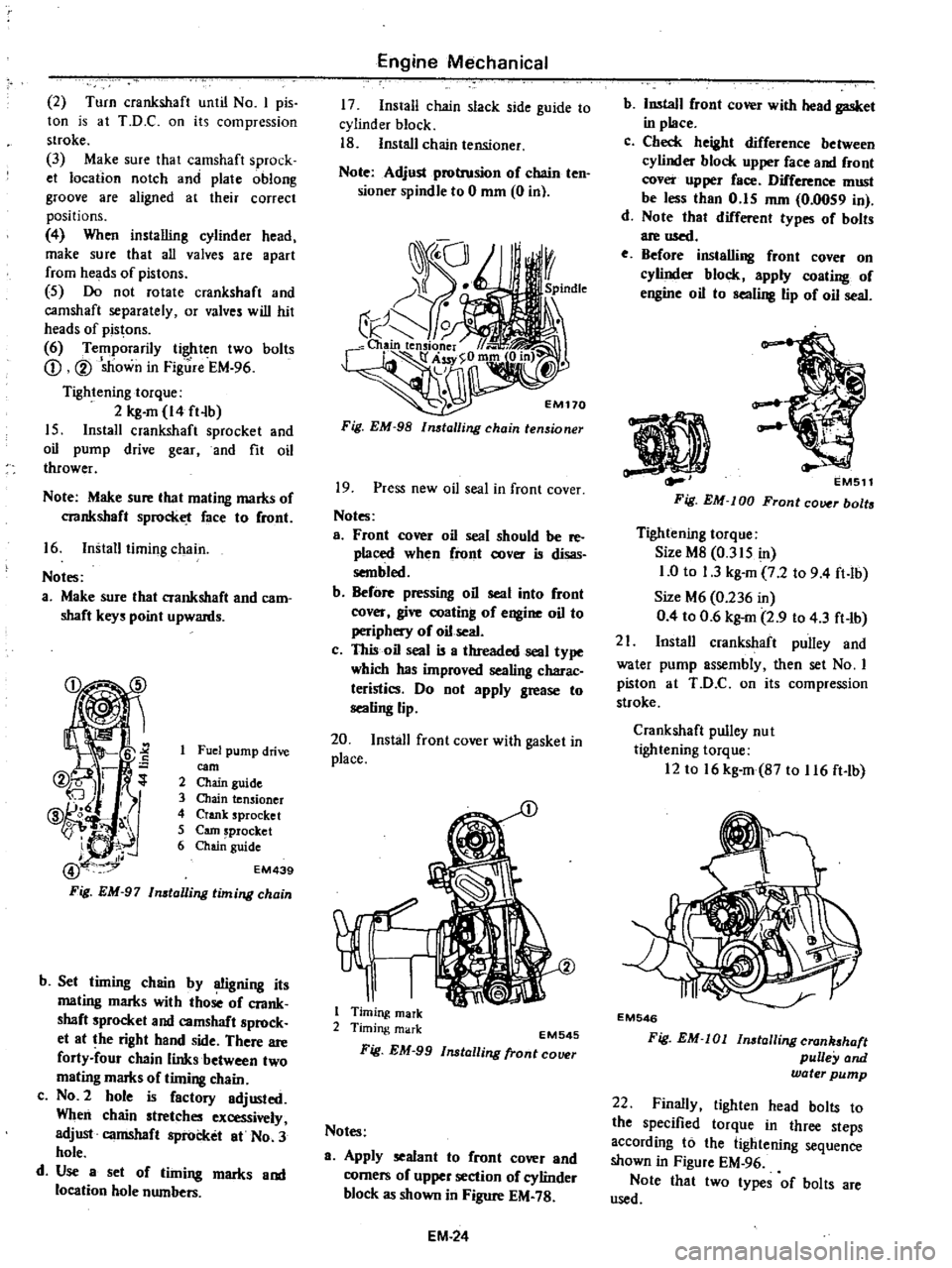
2
Turn
crankshaft
until
No
I
pis
ton
is
at
T
D
C
on
its
compression
stroke
3
Make
sure
thai
camshaft
sprock
et
location
notch
and
plate
oblong
groove
are
aligned
at
their
correct
positions
4
When
installing
cylinder
head
make
sure
that
all
valves
are
apart
from
heads
of
pistons
5
Do
not
rotate
crankshaft
and
camshaft
separately
or
valves
will
hit
heads
of
pistons
6
Temporarily
tighten
two
bolts
CD
V
sJiown
in
Fig
re
EM
96
Tightening
torque
2
kg
m
14
ft
b
15
Install
crankshaft
sprocket
and
oil
pump
drive
gear
and
fit
oil
thrower
Note
Make
sure
lhat
maling
marks
of
crankshaft
sprocket
face
10
Cront
16
Install
timing
chain
Noles
a
Make
sure
that
crankshaft
and
cam
shaft
keys
point
upwards
Fuel
pump
drive
earn
2
Chain
guide
3
Chain
tensioner
4
Crank
sprocket
5
earn
sprocket
6
Chai
guide
EM439
b
Set
timing
chain
by
OOgning
its
mating
marks
with
those
oC
crank
shaft
sprocket
and
camshaft
sprock
et
at
the
right
hand
side
There
are
forty
four
chain
links
between
two
mating
marks
of
timing
chain
c
NO
2
hole
is
Cactory
adjusted
When
chain
stretches
excessively
adjust
camshaft
sprocket
at
No
3
hole
d
Use
a
set
of
timing
marks
and
location
hole
numbers
Engine
Mechanical
17
Install
chain
slack
side
guide
to
cylinder
block
18
Install
chain
tensioner
Note
Adjust
protrusion
oC
chain
ten
sioner
spindle
to
0
mm
0
in
Fig
EM
98
lmtalling
chain
tensioner
19
Press
new
oil
seal
in
front
cover
Notes
a
Front
cover
oil
seal
should
be
reo
placed
when
Cront
cover
is
disas
sembled
b
BeCore
pressing
oil
seal
into
Cront
cover
give
coating
of
engine
oil
to
periphery
of
oil
seal
c
This
oil
seal
is
a
threaded
seal
type
which
has
improved
sealing
charac
teristics
Do
not
apply
grease
to
sealing
lip
20
Install
front
cover
with
gasket
in
place
1
Timing
mark
2
Timing
mark
EM545
Fig
EM
99
Installing
fronl
COlHlr
Notes
a
Apply
sealant
to
Cront
cover
and
corners
oC
upper
section
of
cylinder
block
as
shown
in
Figure
EM
78
EM
24
b
Install
Cront
cover
with
head
gasket
in
place
c
Check
height
diCCerence
between
cylinder
block
upper
Cace
and
Cront
cover
upper
Cace
DifCerence
must
be
less
than
0
15
mm
0
0059
in
d
Note
that
difCerent
types
oC
bolts
are
used
e
Before
installing
front
cover
on
cylinder
block
apply
coating
oC
engine
oil
10
sealing
lip
of
oil
seal
EMS11
Fig
EM
lOD
Front
cover
bolts
Tightening
torque
Size
M8
0
315
in
1
0
to
1
3
kg
m
7
2
to
9
4
ft
lb
Size
M6
0
236
in
0
4
to
0
6
kg
m
2
9
to
4
3
ft
lb
21
Install
crankshaft
pulley
and
water
pump
assembly
then
set
No
I
piston
at
ToO
C
on
its
compression
stloke
Crankshaft
pulley
nu
I
tightening
torque
12
to
16
kg
m
B7
to
116
ft
lb
EM546
Fig
EM
Ol
lnstallingcran
haft
pulley
and
water
pump
22
Finally
tighten
head
bolts
to
the
specified
torque
in
three
steps
according
to
the
lightening
sequence
shown
in
Figure
EM
96
Note
thai
Iwo
types
of
bolts
are
used
Page 73 of 537
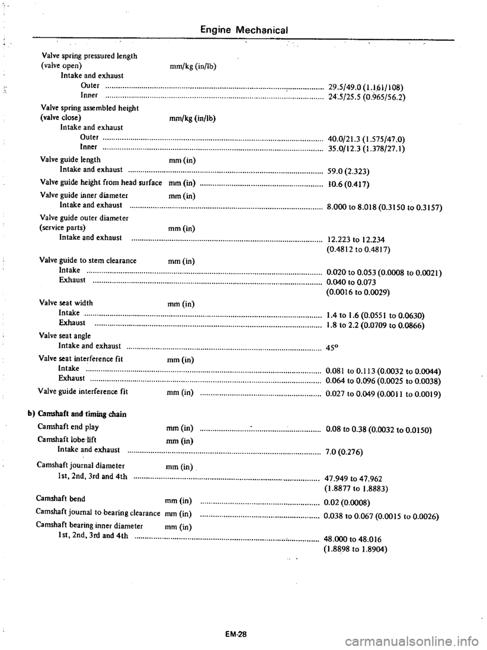
Valve
spring
pressured
length
valve
open
Intake
and
exhaust
Outer
Inner
Valve
spring
assembled
height
valve
close
Intake
and
exhaust
Outer
Inner
Valve
guide
length
Intake
and
exhaust
Valve
guide
height
from
head
surface
Valve
guide
inner
diameter
Intake
and
exhaust
Valve
guide
outer
diameter
service
parts
Intake
and
exhaust
Valve
guide
to
stem
clearance
Intake
Exhaust
Valve
seat
width
Intake
Exhaust
Valve
seat
angle
Intake
and
exhaust
Valve
seat
interference
fit
Intake
Exhaust
Valve
guide
interference
fit
b
Camshaft
and
timing
chain
Camshaft
end
play
Camshaft
lobe
ift
Intake
and
exhaust
Camshaft
joumal
diameter
1st
2nd
3rd
and
4th
Engine
Mechanical
mm
kg
in
lb
mm
kg
in
lb
mm
in
mIll
in
mm
in
mm
in
mm
in
mm
in
mm
in
mm
in
rnm
in
rnm
in
mm
in
Camshaft
bend
mm
in
Camshaft
journal
to
bearing
clearance
mm
in
Camshaft
bearing
inner
diameter
rnm
in
1st
2nd
3rd
and
4th
29
5
49
0
1
IM
108
24
5
25
5
0
965
56
2
40
0
21
3
1
575
47
0
35
0
12
3
1
378
27
I
59
0
2
323
10
6
0
417
8
000
to
8
018
0
3150
to
0
3157
12
223
to
12
234
0
4812
to
0
4817
0
020
to
0
053
0
0008
to
0
0021
0
040
to
0
073
0
0016
to
0
0029
1
4
to
1
6
0
0551
to
0
0630
1
8
to
2
2
0
0709
to
0
0866
450
0
081
to
0
113
0
0032
to
0
0044
0
064
to
0
096
0
0025
to
0
0038
0
027
to
0
049
0
0011
to
0
0019
0
08
to
038
0
0032
to
0
0150
7
0
0
276
47
949
to
47
962
1
8877
to
1
8883
0
02
0
0008
0
Q38
to
0
067
0
00
I
5
to
0
0026
48
000
to
48
016
1
8898
to
1
8904
EM
28
Page 75 of 537
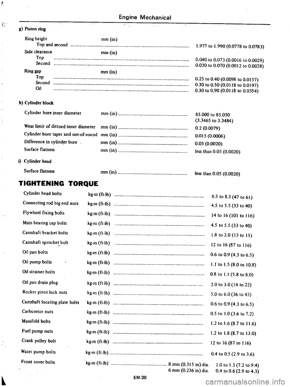
Engine
Mechanical
g
Piston
ring
Ring
height
Top
and
second
Side
clearance
Top
Second
Ring
gap
Top
Second
Oil
mm
in
mrn
in
mm
in
h
Cylinder
block
Cylinder
bore
inner
diameter
mm
in
Wear
limit
of
dittoed
inner
diameter
Cylinder
bore
taper
and
out
of
round
Difference
in
cylind
bore
Surface
flatness
mm
in
mm
in
mm
in
mm
in
i
Cylinder
head
Surface
flatness
mm
in
TIGHTENING
TORQUE
Cylinder
head
bolts
kg
m
fl
lb
Connecting
rod
big
end
nuts
kg
m
ft
Ib
Flywheel
fixing
bolts
kg
m
ft
Ib
Main
bearing
cap
bolts
kg
m
ft
lb
Camshaft
bracket
bolts
kg
m
ft
lb
Camshaft
sprocket
bolt
kg
m
ft
lb
Oil
pan
bolts
kg
m
ft
1b
Oil
pump
bolts
kg
m
ft
lb
Oil
strainer
bolts
kg
m
ft
lb
Oil
pan
drain
plug
kg
m
ft
lb
Rocker
pivot
lock
nuts
kg
m
ft
Ib
Camshaft
locating
plate
bolts
kg
m
ft
lb
Carburetor
nuts
kg
m
ft
lb
Manifold
bolts
kg
m
ft
lb
Fuel
pump
nuts
kg
m
ft
lb
Crank
pulley
bolt
kg
m
ft
lb
Water
pump
bolts
kg
m
ft
Ib
Front
cover
bolts
kg
m
ft
lb
EM
30
1
977
to
1
990
0
0778
to
0
0783
0
040
to
0
073
0
0016
to
0
0029
0
030
to
0
070
0
0012
to
0
0028
0
25
to
0
40
0
0098
to
0
0157
0
30
to
0
50
0
0118
to
0
0197
0
30
to
0
90
0
0118
to
0
0354
85
000
to
85
050
3
3465
to
3
3484
0
2
0
0079
om
5
0
0006
0
05
0
0020
less
than
0
05
0
0020
less
than
0
05
0
0020
6
5
to
8
5
47
to
61
4
5
to
5
5
33
to
40
14
to
16
101
to
116
4
5
to
5
5
33
to
40
1
8
to
2
0
13
to
15
12
to
16
87
to
116
0
6
to
0
9
4
3
to
6
5
I
J
to
1
5
8
0
to
10
8
0
8
to
1
1
5
8
to
8
0
2
0
to
3
0
14
to
22
5
0
to
6
0
36
to
43
0
6
to
0
9
4
3
to
6
5
0
5
to
1
0
3
6
to
7
2
1
2
to
1
6
8
7
to
11
6
1
2
to
1
8
8
7
to
13
0
12
to
16
87
to
116
0
4
to
0
5
2
9
to
3
6
8
mm
0
315
in
dia
6
mm
0
236
in
dia
1
0
to
1
3
7
2
to
9
4
0
4
to
0
6
2
9
to
4
3
Page 164 of 537
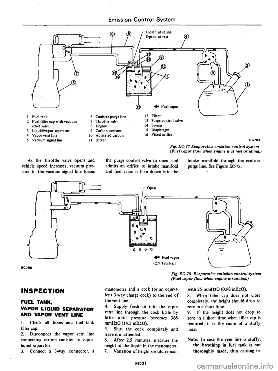
J
1
Fuel
tank
2
Fuel
f1l1er
cap
with
vacuum
relief
valve
3
Liquid
vapor
separator
4
Vapor
vent
line
5
Vacuum
signalUne
As
the
throttle
valve
opens
and
vehicle
speed
increases
vacuum
pres
sure
in
the
vacuum
signal
line
forces
rHL
JL
I
EC785
INSPECTION
FUEL
TANK
VAPOR
LIQUID
SEPARATOR
AND
VAPOR
VENT
LINE
I
Check
all
hoses
and
fuel
tank
mler
cap
2
Disconnect
the
vapor
vent
line
connecting
carbon
canister
to
vapor
liquid
separator
3
Connect
a
3
way
connector
a
Emission
Control
System
Close
at
idling
Open
at
rest
i
J
17
f
Fuel
vapor
6
Canister
purge
line
7
Throttle
valv
8
Engine
9
Carbon
canister
10
Activated
carbon
11
Screen
12
Filter
13
Purge
control
valve
14
Spring
15
Diaphragm
16
Fixed
orifice
i
j
EC784
Fig
EC
77
Evaporative
emu
ion
control
sy
tem
Fuel
vapor
flow
when
engine
i6
at
red
or
idling
the
purge
control
valve
to
open
and
admits
an
orifice
to
intake
manifold
and
fuel
vapor
is
then
drawn
into
the
I
J
o
I
Fuel
vapor
Fresh
air
intake
manifold
through
the
canister
purge
line
See
Figure
EC
7B
Fig
EC
78
Evaporative
emiuion
control
system
Fuel
vapor
flow
when
engine
i
running
manometer
and
a
cock
or
an
equiva
lent
3
way
charge
cock
to
the
end
of
the
vent
line
4
Supply
fresh
air
into
the
vapor
vent
line
through
the
cock
little
by
little
until
pressure
becomes
368
mrnH20
14
5
inH20
5
Shut
the
cock
completely
and
leave
it
unattended
6
After
2
5
minutes
measure
the
height
of
the
liquid
in
the
manometer
7
Variation
of
height
should
remain
EC
31
with
25
mmH20
0
98
inH20
8
When
filler
cap
does
not
close
completely
the
height
should
drop
to
zero
in
a
short
time
9
I
f
the
height
does
not
drop
to
zero
in
a
short
time
when
filler
cap
is
removed
it
is
the
cause
of
a
stuffy
hose
Note
In
case
the
vent
line
is
stuffy
the
breathing
in
fuel
tank
is
not
thoroughly
made
thus
causing
in
Page 225 of 537
l
t
tJ
I
P
o
CUll
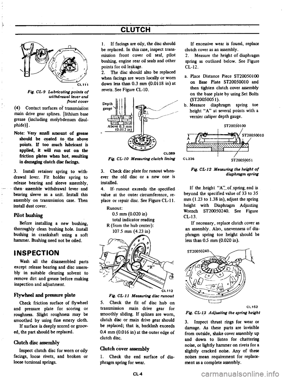
Fig
CL
9
Lubricating
poinu
of
withdrawal
lever
and
front
cover
4
Contact
surfaces
of
transmission
main
drive
gear
splines
lithium
base
grease
including
molybdenum
disul
phide
Note
Very
IIIIJllII
amount
of
grease
should
be
ated
to
the
above
points
If
too
much
iubricant
is
applied
it
will
run
out
on
the
friction
plates
when
hot
resulting
in
d
gi
dutch
disc
facings
3
Install
retainer
spring
to
with
drawal
lever
Fit
holder
spring
to
release
bearing
and
sleeve
assembly
then
assemble
withdrawal
Iever
and
bearing
sleeve
as
a
unit
Install
this
assembly
on
transmission
case
Then
install
dust
cover
Pilot
bushing
Before
installing
a
new
bushing
thoroughly
clean
bushing
hole
Install
bushing
in
crankshaft
using
a
soft
hammer
Bushing
need
not
be
oiled
INSPECTION
Wash
all
the
disassembled
parts
except
release
bearing
and
disc
assem
bly
in
suitable
cleaning
solvent
to
remove
dirt
and
grease
before
making
inspection
and
adjustment
Flywheel
and
pressure
plate
Check
friction
surface
of
flywheel
and
pressure
plate
for
scoring
or
roughness
Slight
roughness
may
be
smoothed
by
using
fme
emery
cloth
If
surface
is
deeply
scored
or
groov
ed
the
part
should
be
replaced
Clutch
disc
at
llembly
Inspect
clutch
disc
for
worn
or
oily
facings
loose
rivets
and
broken
or
loose
torsional
springs
CLUTCH
I
If
facings
are
oily
the
disc
should
be
replaced
In
this
case
inspect
trans
mission
front
cover
oil
seal
pilot
bushing
engine
rear
oil
seals
and
other
points
for
oil
leakage
2
The
disc
should
also
be
replaced
when
facings
are
worn
locally
or
worn
down
less
than
0
3
mm
0
0118
in
at
revels
See
Figure
CL
IO
DePth
ll
I
gauge
II
1
i
h
1
j1
t
f
Above
0
3
rom
10
012
in
CL089
Fig
CL
I0
Me
JIuringclutch
lining
3
Check
disc
plate
for
runout
when
ever
the
old
disc
or
a
new
one
is
installed
4
If
runoutexceeds
the
specified
value
at
the
outer
circumference
Ie
place
or
repair
disc
See
Figure
CL
II
Runou
t
0
5
mm
0
020
in
total
indicator
reading
R
from
the
hub
center
107
5
mm
4
23
in
CL112
Fig
CL
ll
MeOlUring
disc
runout
5
Check
the
fit
of
disc
hub
on
transmission
main
drive
gear
for
smoothly
sliding
If
splines
are
worn
clutch
disc
or
main
drive
gear
should
be
replaced
that
is
backlash
exceeds
0
4
mm
0
016
in
at
the
outer
edge
of
clutch
disc
Clutch
cover
assembly
I
Check
the
end
surface
of
dia
phragm
spring
for
wear
CL
4
If
excessive
wear
is
found
replace
clu
tch
cover
as
an
assembly
2
Measure
the
height
of
diaphragm
spring
as
outlined
below
See
Figure
CL
12
a
Place
Distance
Piece
ST20050100
on
Base
Plate
ST20050010
and
then
tighten
clutch
cover
assembly
on
the
base
plate
by
using
Set
Bolls
ST20050051
b
Measure
diaphragm
spring
toe
height
A
at
several
points
with
a
vernier
caliper
depth
gauge
STl0050100
rJrf
I
Tl
05001O
f
7
C
L23
STl005Q051
Fig
CL
12
Me
uring
the
height
of
diaphragm
pring
If
the
height
A
of
spring
end
is
beyond
the
specified
value
of
33
to
35
mm
1
23
to
1
38
in
adjust
the
spring
height
with
Diaphragm
Adjusting
Wrench
ST20050240
See
Figure
CL
13
If
necessary
replace
clutch
cover
as
an
assembly
Also
unevenness
of
dia
phragm
spring
toe
height
should
be
less
than
05
mm
0
020
in
ST20050240
CL152
Fig
CL
13
AdjlUting
the
spring
height
3
Inspect
thrust
rings
for
wear
or
damage
As
these
parts
are
invisible
from
outside
shake
cover
assembly
up
and
down
to
listen
for
chattering
noise
or
lightly
hammer
on
rivets
for
a
slightly
cracked
noise
Any
of
these
noises
mean
requirement
for
replace
ment
as
a
complete
assembly