ignition DATSUN PICK-UP 1977 Manual PDF
[x] Cancel search | Manufacturer: DATSUN, Model Year: 1977, Model line: PICK-UP, Model: DATSUN PICK-UP 1977Pages: 537, PDF Size: 35.48 MB
Page 463 of 537
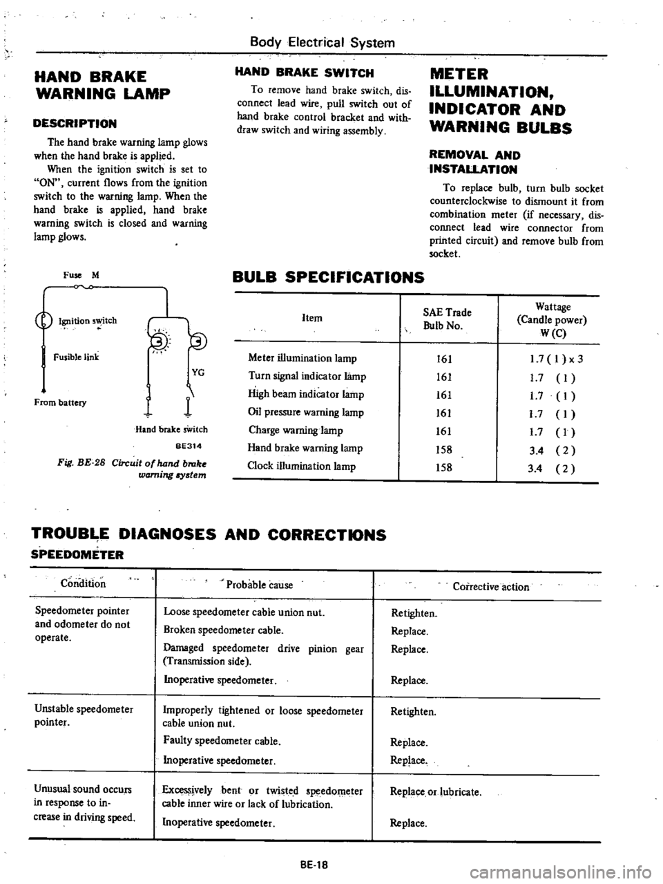
HAND
BRAKE
WARNING
LAMP
DESCRIPTION
The
hand
brake
warning
lamp
glows
when
the
hand
brake
is
applied
When
the
ignition
switch
is
set
to
ON
current
flows
from
the
ignition
switch
to
the
warning
lamp
When
the
hand
brake
is
applied
hand
brake
warning
switch
is
closed
and
warning
lamp
glows
Fuse
M
Ignition
5
tch
Fusible
link
From
battery
I
YG
1
1
Hand
brake
sWitch
BE314
Fig
BE
28
Circuit
of
hand
broke
warning
Iystem
Body
Electrical
System
HAND
BRAKE
SWITCH
To
remove
hand
brake
switch
dis
connect
lead
wire
pull
switch
out
of
hand
brake
control
bracket
and
with
draw
switch
and
wiring
assembly
METER
ILLUMINATION
INDICATOR
AND
WARNING
BULBS
REMOVAL
AND
INSTALLATION
To
replace
bulb
turn
bulb
socket
counterclockwise
to
dismount
it
from
combination
meter
if
necessary
dis
connect
lead
wire
connector
from
printed
circuit
and
remove
bulb
from
socket
BULB
SPECIFICATIONS
Item
Meter
illumination
lamp
Turn
signal
indicator
lamp
High
beam
indicator
lamp
Oil
pressure
warning
lamp
Charge
warning
lamp
Hand
brake
warning
lamp
Clock
illumination
lamp
SAE
Trade
Bulb
No
Wattage
Candle
power
W
e
161
161
161
161
161
158
158
1
7
I
x3
1
7
I
1
7
I
I
7
I
1
7
I
3
4
2
3
4
2
TROUB
E
DIAGNOSES
AND
CORRECTIONS
SPEEDOMETER
Condition
Speedometer
pointer
and
odometer
do
not
operate
Unstable
speedometer
pointer
Unusual
sound
occurs
in
response
to
in
crease
in
driving
speed
Probable
cause
Loose
speedometer
cable
union
nut
Broken
speedometer
cable
Damaged
speedometer
drive
pinion
gear
Transmission
side
Inoperative
speedometer
Improperly
tightened
or
loose
speedometer
cable
union
nut
Faulty
speedometer
cable
Inoperative
speedometer
ExceS
jvelybent
or
twisted
speedOmeter
cable
inner
wire
or
lack
of
lubrication
Inoperative
speedometer
8El8
Coirective
action
Retighten
Replace
Replace
Replace
Retighten
Replace
Replace
Replace
or
lubricate
Replace
Page 464 of 537
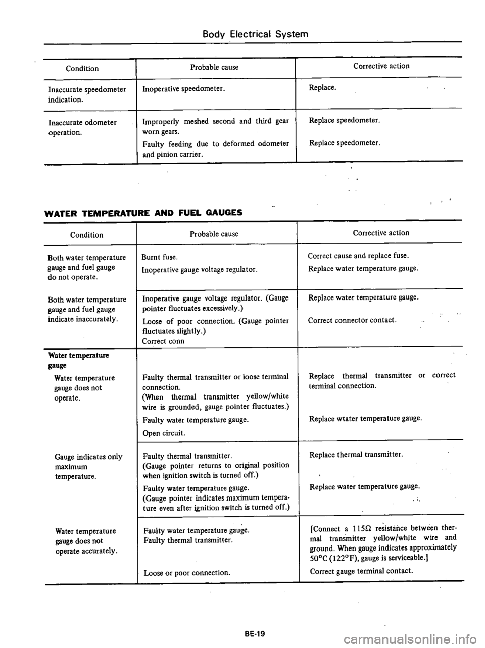
Condition
Inaccurate
speedometer
indication
Inaccurate
odometer
operation
Body
Electrical
System
Probable
cause
Inoperative
speedometer
Improperly
meshed
second
and
third
gear
worn
gears
Faulty
feeding
due
to
deformed
odometer
and
pinion
carrier
WATER
TEMPERATURE
AND
FUEL
GAUGES
Condition
Both
water
temperature
gauge
and
fuel
gauge
do
not
operate
Both
water
temperature
gauge
and
fuel
gauge
indicate
inaccurately
Water
temperature
gauge
Water
temperature
gauge
does
not
operate
Gauge
indicates
only
maximum
temperature
Water
temperature
gauge
does
not
operate
accurately
Probable
cause
Burnt
fuse
Inoperative
gauge
voltage
regulator
Inoperative
gauge
voltage
regulator
Gauge
pointer
fluctuates
excessively
Loose
of
poor
connection
Gauge
pointer
fluctuates
slightly
Correct
conn
Faulty
thermal
transmitter
or
loose
terminal
connection
When
thermal
transmitter
yellow
white
wire
is
grounded
gauge
pointer
fluctuates
Faulty
water
temperature
gauge
Open
circuit
Faulty
thermal
transmitter
Gauge
pointer
returns
to
original
position
when
ignition
switch
is
turned
off
Faulty
water
temperature
gauge
Gauge
pointer
indicates
maximum
tempera
ture
even
after
ignition
switch
is
turned
off
Faulty
water
temperature
gauge
Faulty
thermal
transmitter
Loose
or
poor
connection
BE
19
Corrective
action
Replace
Replace
speedometer
Replace
speedometer
Corrective
action
Correct
cause
and
replace
fuse
Replace
water
temperature
gauge
Replace
water
temperature
gauge
Correct
connector
contact
Replace
thermal
transmitter
or
correct
terminal
connection
Replace
wtater
temperature
gauge
Replace
thermal
transmitter
Replace
water
temperature
gauge
Connect
a
usn
resistance
between
ther
mal
transmitter
yellow
white
wire
and
ground
When
gauge
indicates
approximately
500C
i220F
gauge
is
serviceable
Correct
gauge
terminal
contact
Page 465 of 537
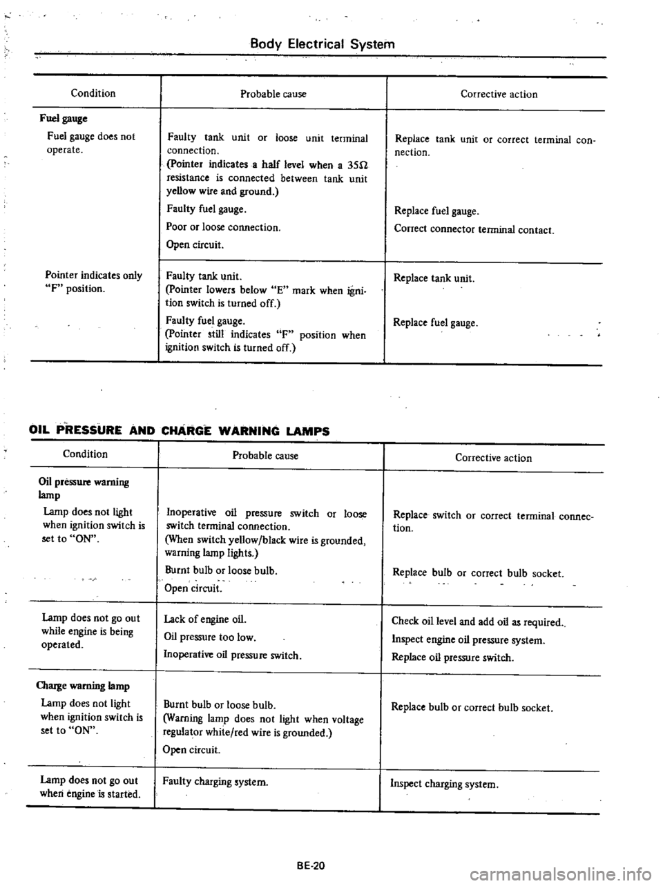
Condition
Fuel
gauge
Fuel
gauge
does
not
operate
Pointer
indicates
only
F
position
Body
Electrical
System
Probable
cause
Faulty
tank
unit
or
loose
unit
terminal
connection
pointer
indicates
a
half
level
when
a
35U
resistance
is
connected
between
tank
unit
yellow
wire
and
ground
Faulty
fuel
gauge
Poor
or
loose
cormection
Open
circuit
Faulty
tank
unit
pointer
lowers
below
E
mark
when
igni
tion
switch
Is
turned
off
Faulty
fuel
gauge
pointer
still
indicates
F
position
when
ignition
switch
is
turned
off
OIL
P
RESSURE
AND
CHARGE
WARNING
LAMPS
Condition
Oil
pressure
wamiug
lamp
Lamp
does
not
light
when
ignition
switch
is
set
to
ON
Lamp
does
not
go
out
while
engine
is
being
operated
OIarge
warning
lamp
Lamp
does
not
light
when
ignition
switch
is
set
to
ON
Lamp
does
not
go
out
when
engine
is
started
Probable
cause
Inoperative
oil
pressure
switch
or
loose
switch
terminal
connection
When
switch
yellow
black
wire
is
grounded
warning
lamp
lights
Burnt
bulb
or
loose
bulb
Open
circuit
Lack
of
engine
oil
Oil
pressure
too
low
Inoperative
oil
pressure
switch
Burnt
bulb
or
loose
bulb
Warning
lamp
does
not
light
when
voltage
regulator
white
red
wire
is
grounded
Open
circuit
Faulty
charging
system
BE
20
Corrective
action
Replace
tank
unit
or
correct
terminal
con
nection
Replace
fuel
gauge
Conect
connector
terminal
contact
Replace
tank
unit
Replace
fuel
gauge
Corrective
action
Replace
switch
OJ
correct
terminal
connee
tion
Replace
bulb
or
correct
bulb
socket
Check
oil
level
and
add
oil
as
required
Inspect
engine
oil
pressure
system
Replace
oil
pressure
switch
Replace
bulb
or
correct
bulb
socket
Inspect
charging
system
Page 466 of 537
Body
Electrical
System
ELECTRICAL
ACCESSORIES
CONTENTS
HORN
DESCRIPTION
REMOVAL
AND
INSTALLATION
IGNITION
SWITCH
REMOVAL
AND
INSTALLATION
INSPECTION
WINDSHIELD
WIPER
AND
WASHER
REMOVAL
AND
INSTALLATION
INSPECTION
RADIO
REMOVAL
AND
INSTALLATION
ADJUSTMENT
CLOCK
REMOVAL
I
NST
ALLA
TION
HEATER
DESCRIPTION
AIRFLOW
HEATER
UNIT
ASSEMBLY
BE
21
BE
21
BE
21
8E
n
BE
22
BE
22
BE
23
BE
23
BE
23
BE
25
BE
25
BE
25
BE
25
BE
25
BE
26
BE
26
BE
26
BE
28
BE
29
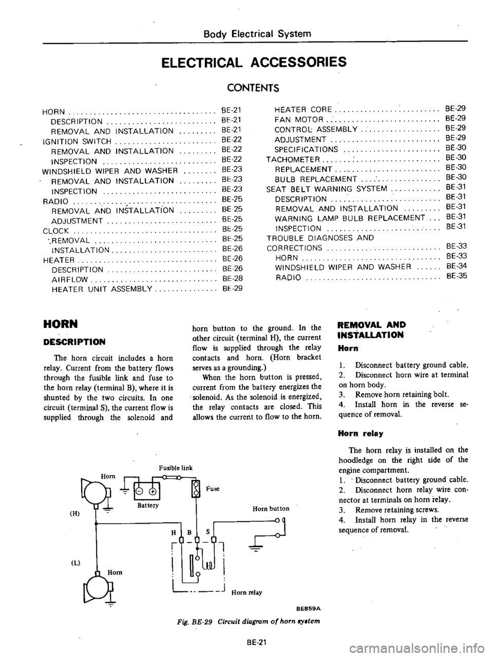
HORN
DESCRIPTION
The
horn
circuit
includes
a
horn
relay
Current
from
the
battery
flows
through
the
fusible
link
and
fuse
to
the
horn
relay
terminal
B
where
it
is
shunted
by
the
two
circuits
In
one
circuit
terminal
S
the
current
flow
is
supplied
through
the
solenoid
and
Fusible
link
Qi
att
Fu
H
I
HIBQ
t
J
JJI
L
J
Hornrelay
Qm
HEATER
CORE
FAN
MOTOR
CONTROL
ASSEMBLY
ADJUSTMENT
SPECIFICATIONS
TACHOMETER
REPLACEMENT
8UL8
REPLACEMENT
SEAT
8ELT
WARNING
SYSTEM
DESCRIPTION
REMOVAL
AND
INSTALLATION
WARNING
LAMP
BULB
REPLACEMENT
INSPECTION
TROUBLE
DIAGNOSES
AND
CORRECTIONS
HORN
WINDSHIELD
WIPER
AND
WASHER
RADIO
Horn
button
BE859A
Fig
BE
29
Circuit
diagram
of
horn
sy
tem
horn
button
to
the
ground
In
the
other
circuit
terminal
H
the
current
flow
is
supplied
through
the
relay
contacts
and
horn
Horn
bracket
serves
as
a
grounding
When
the
horn
button
is
pressed
current
from
the
battery
energizes
the
solenoid
As
the
solenoid
is
energized
the
relay
contacts
are
closed
This
allows
the
current
to
flow
to
the
horn
BE
21
REMOVAL
AND
INSTALLATION
Horn
8E
29
BE
29
BE
29
8E
29
BE
30
BE
30
BE
30
8E
30
8E
31
BE
31
BE
31
8E
31
8E
31
BE
33
8E
33
8E
34
BE
35
I
Disconnect
battery
ground
cable
2
Disconnect
horn
wire
at
terminal
on
horn
body
3
Remove
horn
retaining
bolt
4
Install
horn
in
the
reverse
se
quence
of
removal
Horn
relay
The
horn
relay
is
installed
on
the
hoodIedge
on
the
right
side
of
the
engine
compartment
I
Disconnect
battery
ground
cable
2
Disconnect
horn
relay
wire
con
nector
at
terminals
on
horn
relay
3
Remove
retaining
screws
4
Install
horn
relay
in
the
reverse
sequence
of
removal
Page 467 of 537
Body
Electrical
System
Horn
switch
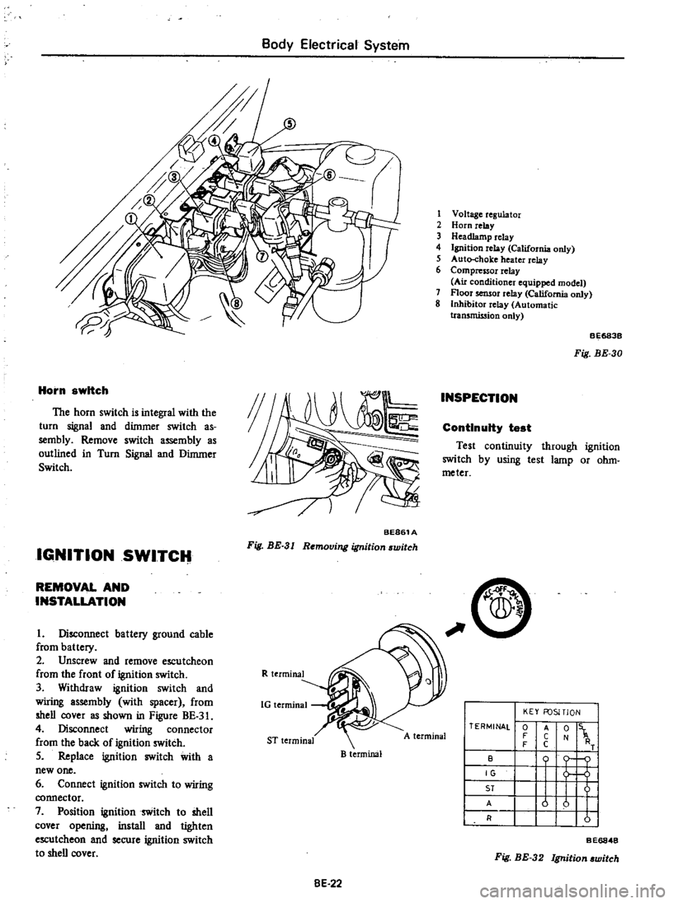
The
horn
switch
is
integral
with
the
turn
signal
and
dimmer
switch
as
sembly
Remove
switch
assembly
as
outlined
in
Turn
Signal
and
Dimmer
Switch
IGNITION
SWITCH
BE861A
Fig
BE
3
I
Removing
ignition
switch
REMOVAL
AND
INSTALLATION
I
Disconnect
battery
ground
cable
from
battery
2
Unscrew
and
remove
escutcheon
from
the
front
of
ignition
switch
3
Withdraw
ignition
switch
and
wiring
assembly
with
spacer
from
shell
cover
as
shown
in
Figure
BE
3
4
Disconnect
wiring
connector
from
the
back
of
ignition
switch
5
Replace
ignition
switch
with
a
new
one
6
Connect
ignition
switch
to
wiring
connector
7
Position
ignition
switch
to
shell
cover
opening
install
and
tighten
escutcheon
and
secure
ignition
switch
to
shell
cover
R
terminal
1G
terminal
ST
terminal
B
terminal
8E
22
1
Voltage
regulator
2
Horn
relay
3
Headlamp
relay
4
Ignition
relay
California
only
5
Auto
choke
heater
relay
6
Compressor
relay
Au
conditioner
equipped
model
7
Floor
sensor
relay
California
only
8
Inhibitor
relay
Automatic
tran5mission
only
INSPECTION
BE683B
Fig
BE
30
ContInuity
test
Test
continuity
through
ignition
switch
by
using
test
lamp
or
ohm
meter
C
A
terminal
TERMINAL
0
F
F
B
IG
ST
A
R
KEY
FOSITlON
t
1
o
j
u
u
I
I
A
C
C
Fig
BE
32
Ignition
witch
BE6848
Page 469 of 537
Body
Electrical
System
tive
terminal
or
B
terminal
and
blue
red
wire
terminal
in
wiring
connector
plug
3
To
check
wiper
low
speed
opera
tion
connect
L
terminal
to
ground
with
ground
cable
or
connect
L
termi
nal
to
black
wire
terminal
make
sure
that
wipers
sweep
at
low
speed
4
To
check
wiper
high
speed
opera
tion
connect
ground
cable
to
H
termi
nal
in
the
same
manner
as
in
step
3
make
sure
that
wipers
sweep
fast
5
During
low
speed
operation
con
nect
E
terminal
to
ground
and
conl
ect
P
and
L
terminals
with
lead
wire
as
shown
in
Figure
BE
38
At
this
time
make
sure
that
auto
stop
mechanism
actuates
to
stop
wiper
blade
at
the
specified
position
6
Wiper
is
in
good
condition
if
above
tests
are
made
as
indicated
H
tenninal
Blue
white
o
@
C
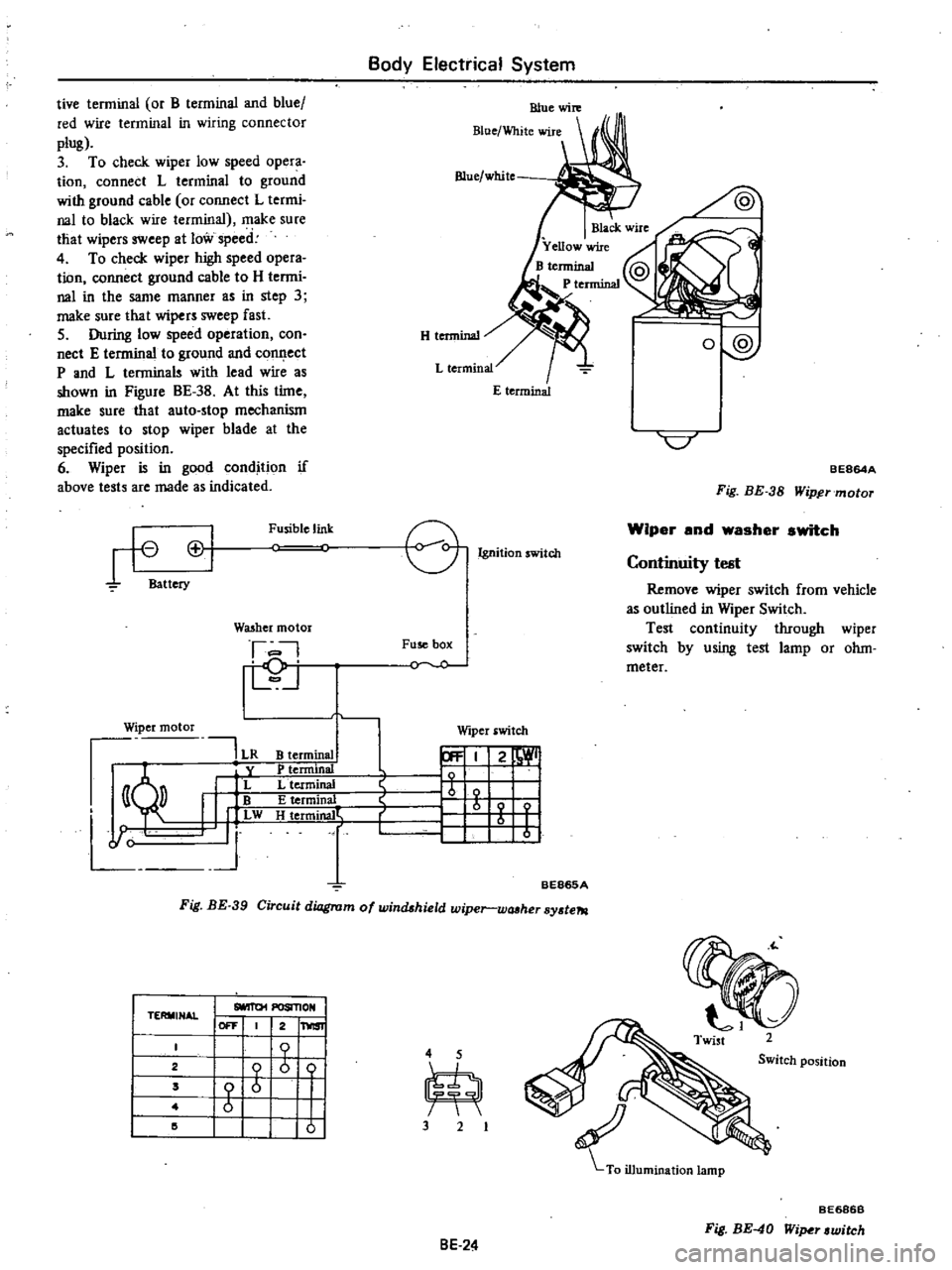
BE864A
Fig
BE
38
Wipftrmotor
rt
Cl
Battery
Fusible
link
e
Ignition
witch
Wiper
and
washer
switch
I
D
j
Fuse
box
Y
O
Continuity
test
Remove
wiper
switch
from
vehicle
as
outlined
in
Wiper
Switch
Test
continuity
through
wiper
switch
by
using
test
lamp
or
ohm
meter
WQ5hcr
motor
Wiper
motor
191
LR
y
I
L
I
w
J
Wiper
switch
B
terminal
P
tenninal
L
terminal
E
terminal
H
t
rmjrW
r
21
1
b
I
r
1
I
I
BE865A
Fig
BE
39
Circuit
diagram
of
windshield
wiper
wtUher
sy
te7tl
TERMINAL
I
SlOIT01
POSIl10N
I
I
OFF
2
1
1
2
I
b
ii
4
5
Switch
position
2
I
Z
m
Z
I
I
I
I
I
I
I
10
I
3
2
BE686B
Fig
BE
40
Wi
r
witch
8E
24
Page 475 of 537
TEMP
lever
1
Move
TEMP
lever
to
the
OFF
position
2
Connect
control
cable
to
the
lever
of
water
ock
when
water
cock
lever
is
pulled
forward
fully
closed
3
Install
control
cable
on
water
cock
bracket
with
cable
retaining
clip
SPECIFICATIONS
Item
FAN
MOTOR
Rated
power
consumption
Revolution
rpm
Fan
dia
mm
in
TACHOMETER
The
tachometer
is
optional
on
model
HL620
It
is
an
integral
part
of
the
ignition
system
It
counts
the
pulses
entering
the
ignition
coil
and
indicates
the
number
of
engine
revolu
tions
REPLACEMENT
I
Remove
battery
ground
cable
2
Remve
cluster
lid
following
instructions
iri
steps
I
to
4
of
Removal
in
Combination
Meter
Body
Electrical
System
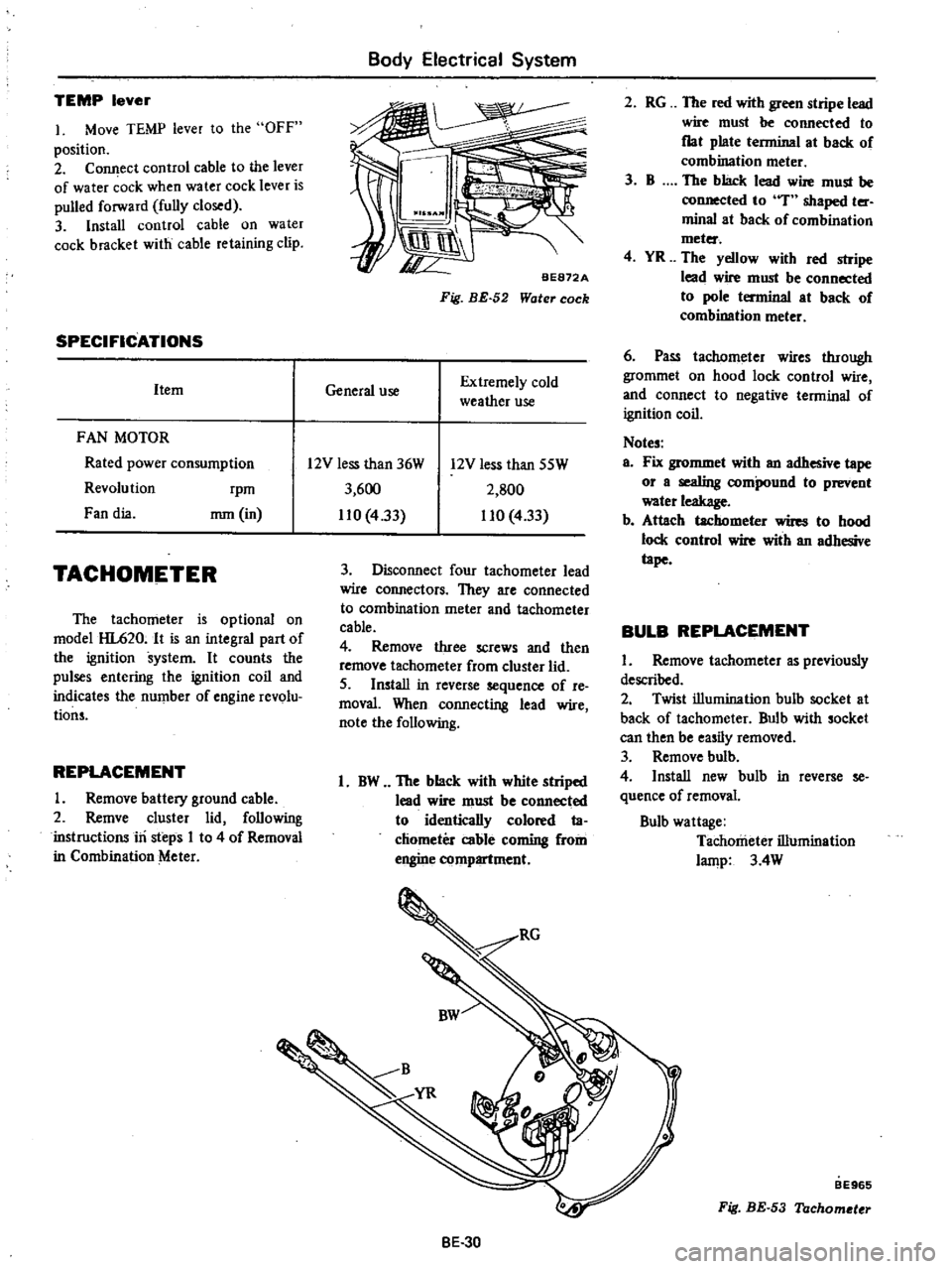
BE872A
Fig
BE
52
Water
cock
General
use
Extremely
cold
weather
use
2
RG
The
red
with
green
stripe
lead
wire
must
be
connected
to
flat
plate
terminal
at
back
of
combination
meter
3
B
The
black
lead
wire
must
be
connected
to
T
shaped
ter
minal
at
back
of
combination
meter
4
YR
The
yellow
with
red
stripe
lead
wire
must
be
connected
to
pole
terminal
at
back
of
combination
meter
6
Pass
tachllmeter
wires
through
grommet
on
hood
lock
control
wire
and
connect
to
negative
terminal
of
ignition
coil
Notes
a
Fix
grommet
with
an
adhesive
tape
or
a
sealing
compound
to
prevent
water
leakage
b
Attach
tachometer
wires
to
hood
lock
control
wire
with
an
adhesive
tape
BULB
REPLACEMENT
I
Remove
tachometer
as
previously
described
2
Twist
illumination
bulh
socket
at
back
of
tachometer
Bulb
with
socket
can
then
be
easily
removed
3
Remove
bulb
4
Install
new
bulb
in
reverse
se
quence
of
removal
Bulb
wattage
Tachometer
illumination
lamp
3
4W
12V
less
than
36W
3
600
110
433
12V
less
than
SSW
2
SOO
110
4
33
3
Disconnect
four
tachometer
lead
wire
connectors
They
are
connected
to
combination
meter
and
tachometer
cable
4
Remove
three
screws
and
then
remove
tachometer
from
cluster
lid
5
Install
in
reverse
sequence
of
re
moval
When
connecting
lead
wire
note
the
following
1
BW
The
black
with
white
striped
lead
wire
must
be
connected
to
identically
colored
ta
chometer
cable
coming
from
engine
compartment
BE
30
BE965
Fig
BE
53
Tachometer
Page 476 of 537
SEAT
BELT
WARNING
SYSTEM
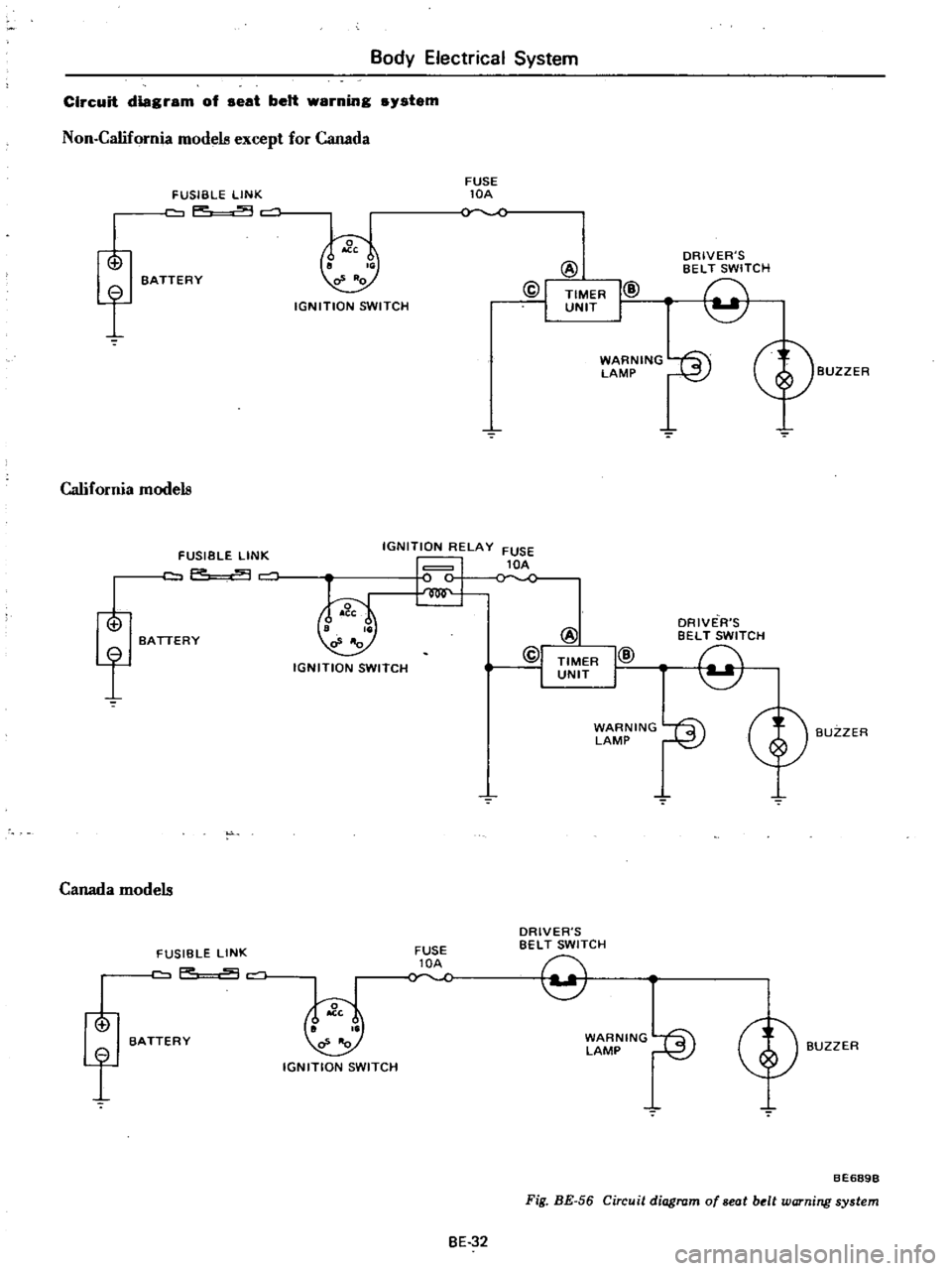
DESCRIPTION
Except
Canada
When
the
ignition
switch
is
turned
to
the
ON
position
the
warning
lamp
comes
on
and
remains
on
for
4
to
8
seconds
The
warning
buzzer
sounds
for
4
to
8
seconds
intermittent
ly
if
the
driver
s
seat
belt
is
not
fastened
properly
The
seat
belt
warning
system
con
sists
of
a
driver
s
belt
switch
a
warning
buzzer
a
warning
lamp
a
timer
unit
and
an
ignition
switch
For
Canada
When
the
ignition
switch
is
turned
Body
Electrical
System
to
the
ON
position
the
warning
lamp
comes
on
and
the
warning
buz
zer
sounds
if
the
driver
s
seat
belt
is
not
fastened
properly
The
seat
belt
warning
system
con
sists
of
a
driver
s
belt
switch
a
warning
buzzer
a
warning
lamp
and
an
igni
tion
switch
REMOVAL
AND
INSTALLATION
Ignition
switch
Refer
to
page
BE
22
for
Removal
and
Installation
Timer
unit
Timer
unit
is
fIXed
on
a
reinforce
ment
behind
glove
box
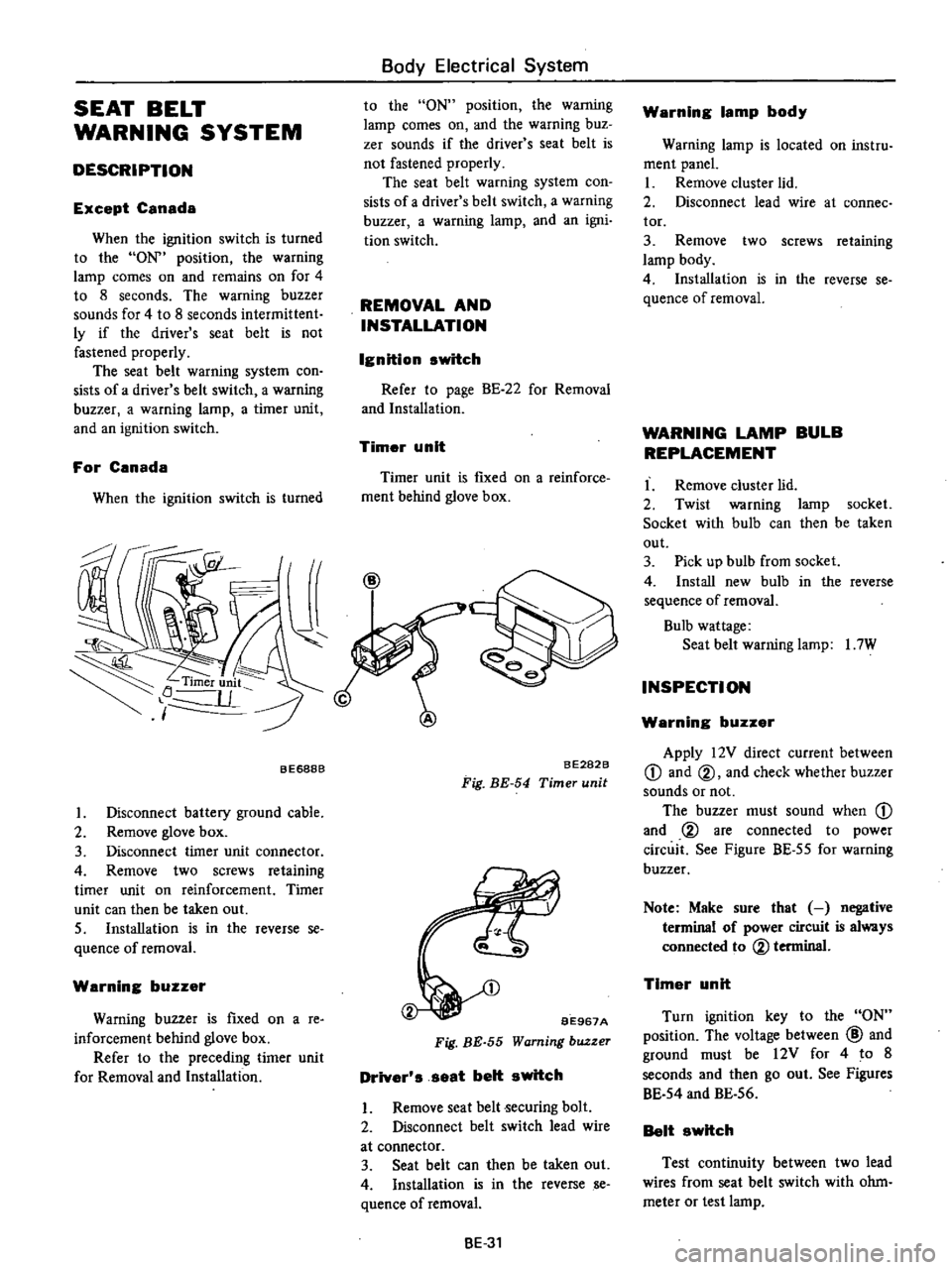
BE688B
I
Disconnect
battery
ground
cable
2
Remove
glove
box
3
Disconnect
timer
unit
connector
4
Remove
two
screws
retaining
timer
unit
on
reinforcement
Timer
unit
can
then
be
taken
out
S
Installation
is
in
the
reverse
se
quence
of
removal
Warning
buzzer
Warning
buzzer
is
fIxed
on
a
re
inforcement
behind
glove
box
Refer
to
the
preceding
timer
unit
for
Removal
and
Installation
BE282B
Fig
BE
54
Timer
unit
BE967A
Fig
BE
55
Warning
buzzer
Driver
s
seat
belt
switch
I
Remove
seat
belt
ecuring
bolt
2
Disconnect
belt
switch
lead
wire
at
connector
3
Seat
belt
can
then
be
taken
out
4
Installation
is
in
the
reverse
se
quence
ofremoval
BE
31
Warning
lamp
body
Warning
lamp
is
located
on
instru
ment
panel
I
Remove
cluster
lid
2
Disconnect
lead
wire
at
connee
tor
3
Remove
two
screws
retaining
lamp
body
4
Installation
is
in
the
reverse
se
quence
of
removal
WARNING
LAMP
BULB
REPLACEMENT
I
Remove
cluster
lid
2
Twist
warning
lamp
socket
Socket
with
bulb
can
then
be
taken
out
3
Pick
up
bulb
from
socket
4
Install
new
bulb
in
the
reverse
sequence
of
removal
Bulb
wattage
Seat
belt
warning
lamp
I
7W
INSPECTION
Warning
buzzer
Apply
12V
direct
current
between
CD
and
@
and
check
whether
buzzer
sounds
or
not
The
buzzer
must
sound
when
CD
and
@
are
connected
to
power
circuit
See
Figure
BE
55
for
warning
buzzer
Note
Make
sure
that
negative
terminal
of
power
circuit
is
always
connected
to
@
terminal
Timer
unit
Turn
ignition
key
to
the
ON
position
The
voltage
between
@
and
ground
must
be
12V
for
4
to
8
seconds
and
then
go
out
See
Figures
BE
54
and
BE
56
Belt
switch
Test
continuity
between
two
lead
wires
from
seat
belt
switch
with
ohm
meter
or
test
lamp
Page 477 of 537
Body
Electrical
System
Circuit
diagram
of
seat
belt
warning
system
Non
California
modela
except
for
Canada
f
FUSIBLE
LINK
p
c
o
BATTERY
California
modela
f
Canada
modela
o
f
FUSIBLE
LINK
F
9
BATTERY
FUSIBLE
LINK
aP
c
BATTERY
IGNITION
SWITCH
FUSE
lOA
@
@I
TIMER
UNIT
I@
I
WARNING
fS
LAMP
l
2
IGNITION
RELAY
FUSE
1
lC
1
lOA
IGNITION
SWITCH
N
IGN
ITION
SWITCH
FUSE
lOA
BE
32
DRIVER
S
BELT
SWITCH
9
ORIVE
R
S
BELT
SWITCH
9
WARNING
r
i
LAMP
I
2
J
DRIVER
S
BELT
SWITCH
9
WARNING
fS
LAMP
I
2
J
Cf
BUZZER
BUZZER
BUZZER
BE689B
Fig
BE
56
Circuit
diagram
of
seat
belt
warning
system
Page 480 of 537
Body
Electrical
System
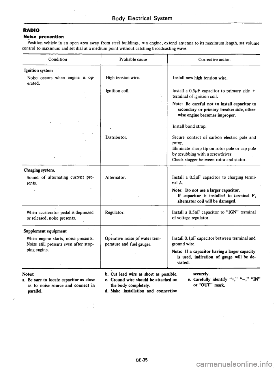
RADIO
Noise
prevention
Position
vehicle
in
an
open
area
away
from
steel
buildings
run
engine
extend
antenna
to
its
maximum
length
set
volume
control
to
maximum
and
set
dial
at
a
medium
point
without
catching
broadcasting
wave
Condition
Ignition
system
Noise
occurs
when
engine
is
op
erated
Charging
system
Sound
of
alternating
current
pre
sents
When
accelerator
pedal
is
depressed
or
released
noise
presents
Supplement
equipment
When
engine
starts
noise
presents
Noise
still
presents
even
after
stop
ping
engine
Notes
a
Be
sure
to
locate
capacitor
as
close
as
to
noise
source
and
connect
in
parallel
Probable
cause
Corrective
action
High
tension
wire
Install
new
high
tension
wire
Ignition
coil
Install
a
0
51lF
capacitor
to
primary
side
terminal
of
ignition
coil
Note
Be
careful
not
to
install
capacitor
to
secondary
or
primary
breaker
side
other
wise
engine
becomes
improper
Install
bond
strap
Distributor
Secure
contact
of
carbon
electric
pole
and
rotor
Eliminate
sharp
tip
on
rotor
pole
or
cap
pole
by
scrubbing
with
a
screwdriver
Check
stagger
between
rotor
and
stator
Alternator
Install
a
0
51lF
capacitor
to
charging
termi
nalA
Note
Do
not
use
a
larger
capacitor
If
capacitor
is
installed
to
terminal
F
alternator
coil
will
be
damaged
Regulator
Install
a
0
51lF
capacitor
to
IGN
terminal
of
voltage
regulator
Operative
noise
of
water
tem
perature
and
fuel
gauges
Install
O
IIlF
capacitor
between
terminal
and
ground
wire
Note
If
a
capacitor
having
a
larger
capacity
is
used
indication
of
gauge
will
be
de
viated
b
Cut
lead
wire
as
short
as
possible
c
Ground
wire
should
be
attached
on
the
body
completely
d
Make
installation
and
connection
securely
e
Carefully
identify
or
OUT
mark
IN
BE
35