ignition DATSUN PICK-UP 1977 Workshop Manual
[x] Cancel search | Manufacturer: DATSUN, Model Year: 1977, Model line: PICK-UP, Model: DATSUN PICK-UP 1977Pages: 537, PDF Size: 35.48 MB
Page 173 of 537
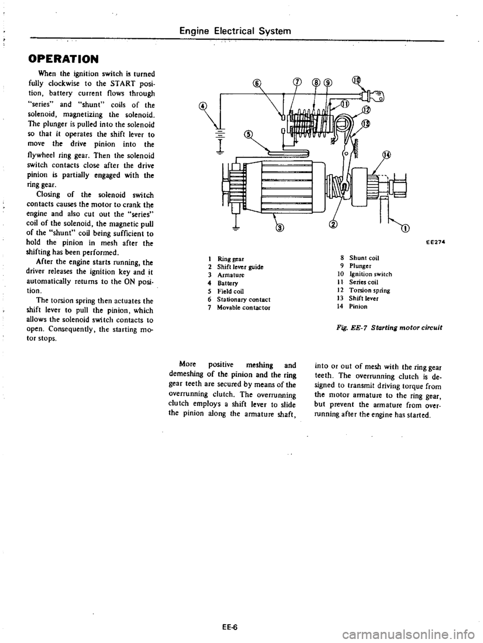
OPERATION
When
the
ignition
switch
turned
fully
clockwise
to
the
START
posi
tion
battery
current
flows
through
series
and
shunt
coils
of
the
solenoid
magnetizing
the
solenoid
The
plunger
is
pulled
into
the
solenoid
so
that
it
operates
the
shift
lever
to
move
the
drive
pinion
into
the
flywheel
ring
gear
Then
the
solenoid
switch
contacts
close
after
the
drive
pinion
is
partially
engaged
with
the
ring
gear
Closing
of
the
solenoid
switch
contacts
c
uses
the
motor
to
crank
the
engine
and
also
cut
out
the
series
coil
of
the
solenoid
the
magnetic
pull
of
the
shunt
coil
being
sufficient
to
hold
the
pinion
in
mesh
after
the
shifting
has
been
performed
After
the
engine
starts
running
the
driver
releases
the
ignition
key
and
it
automatically
returns
to
the
ON
posi
tion
The
torsion
spring
then
actuates
the
shift
lever
to
pull
the
pinion
which
allows
the
solenoid
swi
tch
contacts
to
open
Consequently
the
starting
mo
tor
stops
Engine
Electrical
System
I
I
Ring
gear
2
Shift
lever
guide
3
Armature
4
Battery
5
Field
coil
6
Stationary
contact
7
Monble
contactor
More
positive
meshing
and
demeshing
of
the
pinion
and
the
ring
gear
teeth
are
secured
by
means
of
the
overrunning
clutch
The
overruIUling
clutch
employs
a
shift
lever
to
slide
the
pinion
along
the
armature
shaft
EE
6
F
l
cp
o
r
1
I
I
W
m
EE274
8
Shunt
coil
9
Plunger
10
Ignition
switch
11
Series
coil
12
Torsion
spring
13
Shift
lever
14
Pinion
Fig
EE
7
Starting
motor
circuit
into
or
out
of
mesh
with
the
ring
gear
teeth
The
overrunning
clutch
is
de
signed
to
transmit
driving
torque
from
the
motor
armature
to
the
ring
gear
but
prevent
the
armature
from
over
running
after
the
engine
has
started
Page 179 of 537
Condition
Engine
Electrical
System
Probable
cause
Starting
motor
cranks
slowly
Dirty
or
worn
commutator
Armature
rubs
field
coil
Damaged
solenoid
switch
Starting
motor
operates
but
does
not
crank
engine
Worn
pinion
Locked
pinion
guide
Worn
ring
gear
Starting
motor
will
not
disengage
even
if
ignition
switch
is
turned
off
Damaged
solenoid
switch
Damaged
gear
teeth
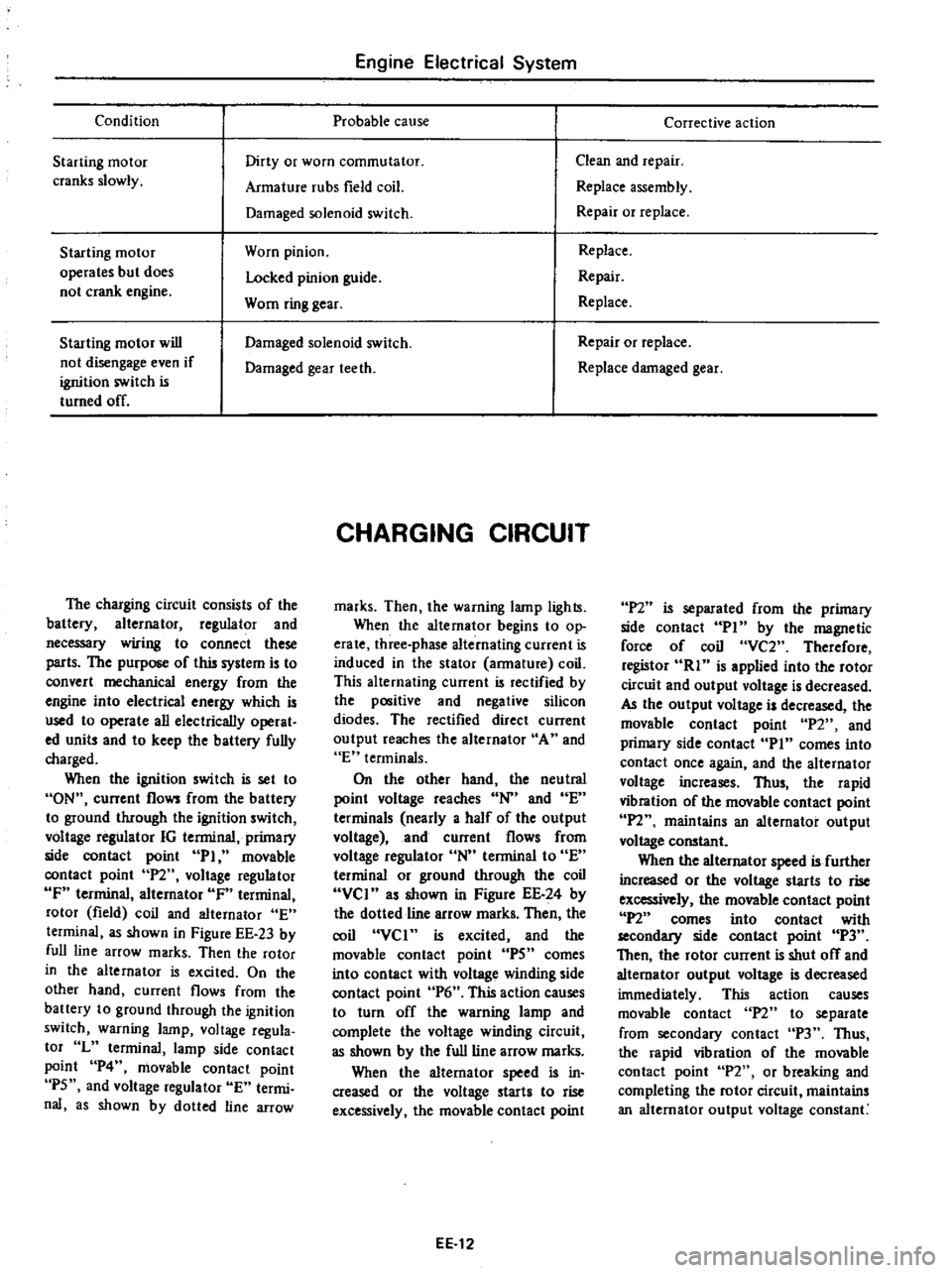
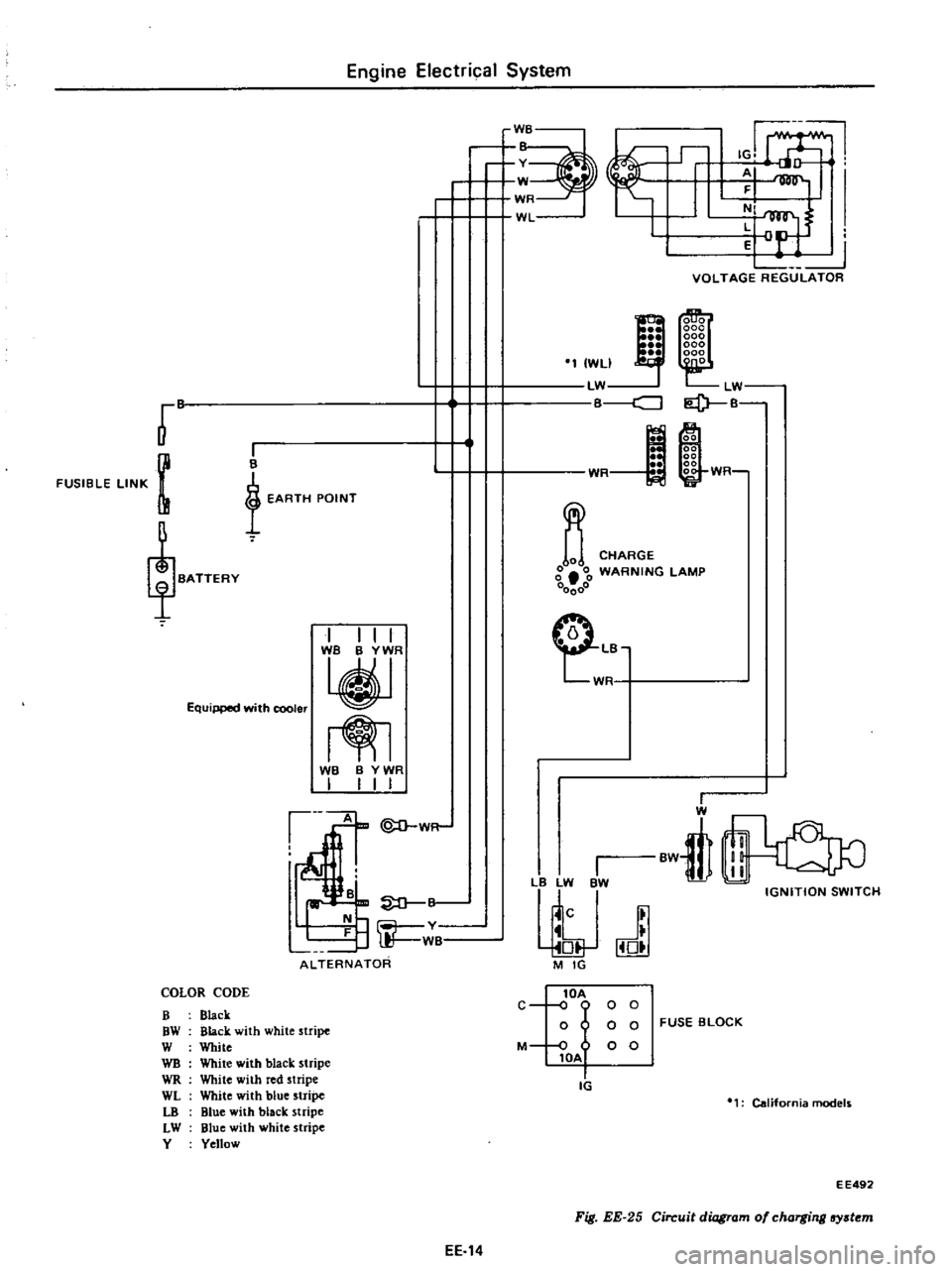
The
charging
circuit
consists
of
the
battery
alternator
regulator
and
necessary
wiring
to
connect
these
parts
The
purpose
of
this
system
is
to
convert
mechanical
energy
from
the
engine
into
electrical
energy
which
is
used
to
operate
all
electrically
operat
ed
units
and
to
keep
the
battery
fully
charged
When
the
ignition
switch
is
set
to
ON
current
flows
from
the
battery
to
ground
through
the
ignition
switch
voltage
regulator
IG
terminal
primary
side
contact
point
PI
movable
contact
point
P2
voltage
regulator
IF
terminal
alternator
IF
terminal
rotor
field
coil
and
alternator
E
terminal
as
shown
in
Figure
EE
23
by
full
line
arrow
marks
Then
the
rotor
in
the
alternator
is
excited
On
the
other
hand
current
flows
from
the
battery
to
ground
through
the
ignition
switch
warning
lamp
voltage
regula
tor
L
terminal
lamp
side
contact
point
P4
movable
contact
point
P5
and
voltage
regulator
E
termi
nal
as
shown
by
dotted
line
arrow
CHARGING
CIRCUIT
marks
Then
the
warning
lamp
lights
When
the
alternator
begins
to
op
erate
three
phase
alternating
current
is
induced
in
the
stator
armature
coil
This
alternating
current
is
rectified
by
the
positive
and
negative
silicon
diodes
The
rectified
direct
current
output
reaches
the
alternator
A
and
E
terminals
On
the
other
hand
the
neutral
point
voltage
reaches
N
and
E
terminals
nearly
a
half
of
the
output
voltage
and
current
flows
from
voltage
regulator
N
terminal
to
E
terminal
or
ground
through
the
coil
VCI
as
shown
in
Figure
EE
24
by
the
dotted
line
arrow
marks
Then
the
coil
VCI
is
excited
and
the
movable
contact
point
IPS
comes
into
contact
with
voltage
winding
side
contact
point
P6
This
action
causes
to
turn
off
the
warning
lamp
and
complete
the
voltage
winding
circuit
as
shown
by
the
full
line
arrow
marks
When
the
alternator
speed
is
in
creased
or
the
voltage
starts
to
rise
excessively
the
movable
contact
point
EE
12
Corrective
action
Clean
and
repair
Replace
assembly
Repair
or
replace
Replace
Repair
Replace
Repair
or
replace
Replace
damaged
gear
P2
is
separated
from
the
primary
side
contact
PI
by
the
magnetic
force
of
coil
VC2
Therefore
registor
RI
is
applied
into
the
rotor
circuit
and
output
voltage
is
decreased
AJ
the
output
voltage
is
decreased
the
movable
contact
point
P2
and
primary
side
contact
Pin
comes
into
contact
once
again
and
the
alternator
voltage
increases
Thus
the
rapid
vibration
of
the
movable
contact
point
IPl
maintains
an
alternator
output
voltage
constant
When
the
alternator
speed
is
further
increased
or
the
voltage
starts
to
rise
excessively
the
movable
contact
point
P2
comes
into
contact
with
secondllJ
side
contact
point
P3
Then
the
rotor
current
is
shut
off
and
alternator
output
voltage
is
decreased
immediately
This
action
causes
movable
contact
n
to
separate
from
secondary
contact
P3
Thus
the
rapid
vibration
of
the
movable
contact
point
P2
or
breaking
and
completing
the
rotor
circuit
maintains
an
alternator
output
voltage
constant
Page 181 of 537
Engine
Electrical
System
B
v
W
WR
WL
L2
VOLTAGE
REGULATOR
co
LW
I
P
B
r
FUSIBLE
LINK
m
I
WLI
LW
cJ
I
B
t
EARTH
POINT
m
WR
WR
CHARGE
g
00
WARNING
lAMP
00000
Equipped
with
cooler
I
I
I
I
TjT
m
CLB
W
WB
B
YWR
I
I
I
I
1
W
B
rn
ALTERNATOR
I
l
LW
BW
j
J
M
IG
I
W
BwtIl
IGNITION
SWITCH
COLOR
CODE
B
Black
OW
Black
with
white
stripe
W
White
WB
White
with
black
stripe
WR
White
with
red
stripe
WL
White
with
blue
stripe
LO
Blue
with
black
stripe
LW
Blue
with
white
stripe
Y
Yellow
lOA
C
o
0
0
0
o
0
0
FUSE
BLOCK
M
0
0
0
lOA
Ii
California
models
E
E492
Fig
EE
25
Circuit
diagram
of
charging
lfY
t
m
EE
14
Page 193 of 537
NON
CALIFORNIA
MODELS
Engine
Electrical
System
IGNITION
CIRCUIT
CONTENTS
EE
26
CALIFORNIA
MODELS
EE
2B
NON
CALIFORNIA
MODELS
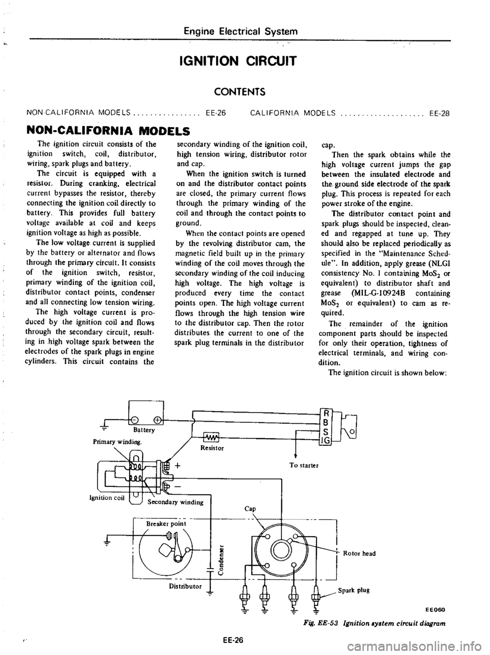
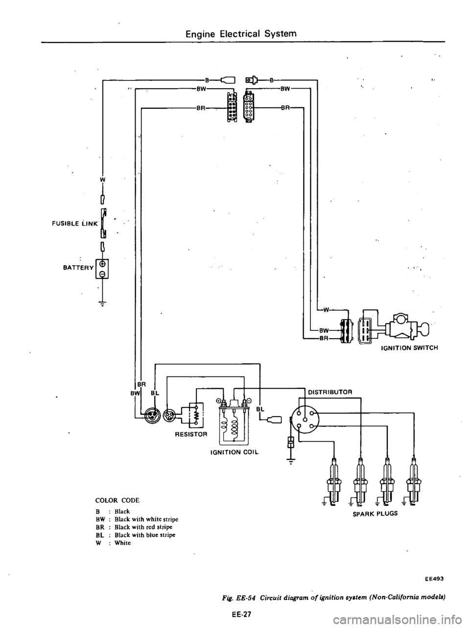
The
ignition
circuit
consists
of
the
ignition
switch
coil
distributor
wiring
spark
plugs
and
battery
The
circuit
is
equipped
with
a
resistor
During
cranking
electrical
current
bypasses
the
resistor
thereby
connecting
the
ignition
coil
directly
to
battery
This
provides
full
battery
voltage
available
at
coil
and
keeps
ignition
voltage
as
high
as
possible
The
low
voltage
current
is
supplied
by
the
battery
or
alternator
and
flows
through
the
primary
circuit
It
consists
of
the
ignition
switch
resistor
primary
winding
of
the
ignition
coil
distributor
contact
points
condenser
and
all
connecting
low
tension
wiring
The
high
voltage
current
is
pro
duced
by
the
ignition
coil
and
flows
through
the
secondary
circuit
result
ing
in
high
voltage
spark
between
the
electrodes
of
the
spark
plugs
in
engine
cylinders
This
circuit
contains
the
0
cl
Battery
Ignition
coil
secondary
winding
of
the
ignition
coil
high
tension
wiring
distributor
rotor
and
cap
When
the
ignition
switch
is
turned
on
and
the
distributor
contact
points
are
closed
the
primary
current
flows
through
the
primary
winding
of
the
coil
and
through
the
contact
points
to
ground
When
the
contact
points
are
opened
by
the
revolving
distributor
earn
the
magnetic
field
built
up
in
the
primary
winding
of
the
coil
moves
through
the
secondary
winding
of
the
coil
inducing
high
voltage
The
high
voltage
is
produced
every
time
the
contact
points
open
The
high
voltage
current
flows
through
the
high
tension
wire
to
the
distributor
cap
Then
the
rotor
distributes
the
current
to
one
of
the
spark
plug
terminals
in
the
distributor
Re5istor
To
starter
Secondary
winding
Cap
Breaker
point
f
Distributor
EE
26
cap
Then
the
spark
obtains
while
the
high
voltage
current
jumps
the
gap
between
the
insulated
electrode
and
the
ground
side
electrode
of
the
spark
plug
This
process
is
repeated
for
each
power
stroke
of
the
engine
The
distributor
contact
point
and
spark
plugs
should
be
inspected
clean
ed
and
regapped
at
tune
up
They
should
also
be
replaced
periodically
as
specified
in
the
Maintenance
Sched
ule
In
addition
apply
grease
NLGl
consistency
No
I
containing
MoS2
or
equivalent
to
distributor
shaft
and
grease
MIL
G
l0924B
containing
MoS2
or
equivalent
to
cam
as
reo
quired
The
remainder
of
the
ignition
component
parts
should
be
inspected
for
only
their
operation
tightness
of
electrical
terminals
and
wiring
con
dition
The
ignition
circuit
is
shown
below
IR
IB
I
is
21
J
g
Rotor
head
EE060
Fig
EE
53
Ignition
ydem
circuit
diagram
Page 194 of 537
FUSIBLE
LtNK
m
Engine
Electrical
System
E
CJI2t
Bf
o
00
00
fOl
R
BL
I
ti
L
oj
L
C
J
RESISTOR
IGNITION
COIL
COLOR
CODE
B
Black
OW
Black
with
white
stripe
DR
Black
with
red
stripe
aL
Black
with
blue
stripe
W
White
W
R
Wj
BW
BR
IGNITION
SWtTCH
DISTRtBUTOR
jjj
SPARK
PLUGS
EE493
EE
27
Fig
EE
54
Circuit
diagram
of
ignition
ByJt
m
Non
California
models
Page 195 of 537
Primary
winding
1
Ignition
coo
I
Secondary
winding
CALIFORNIA
MODELS
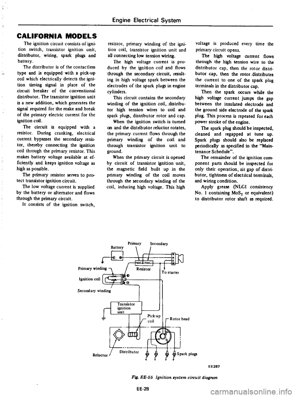
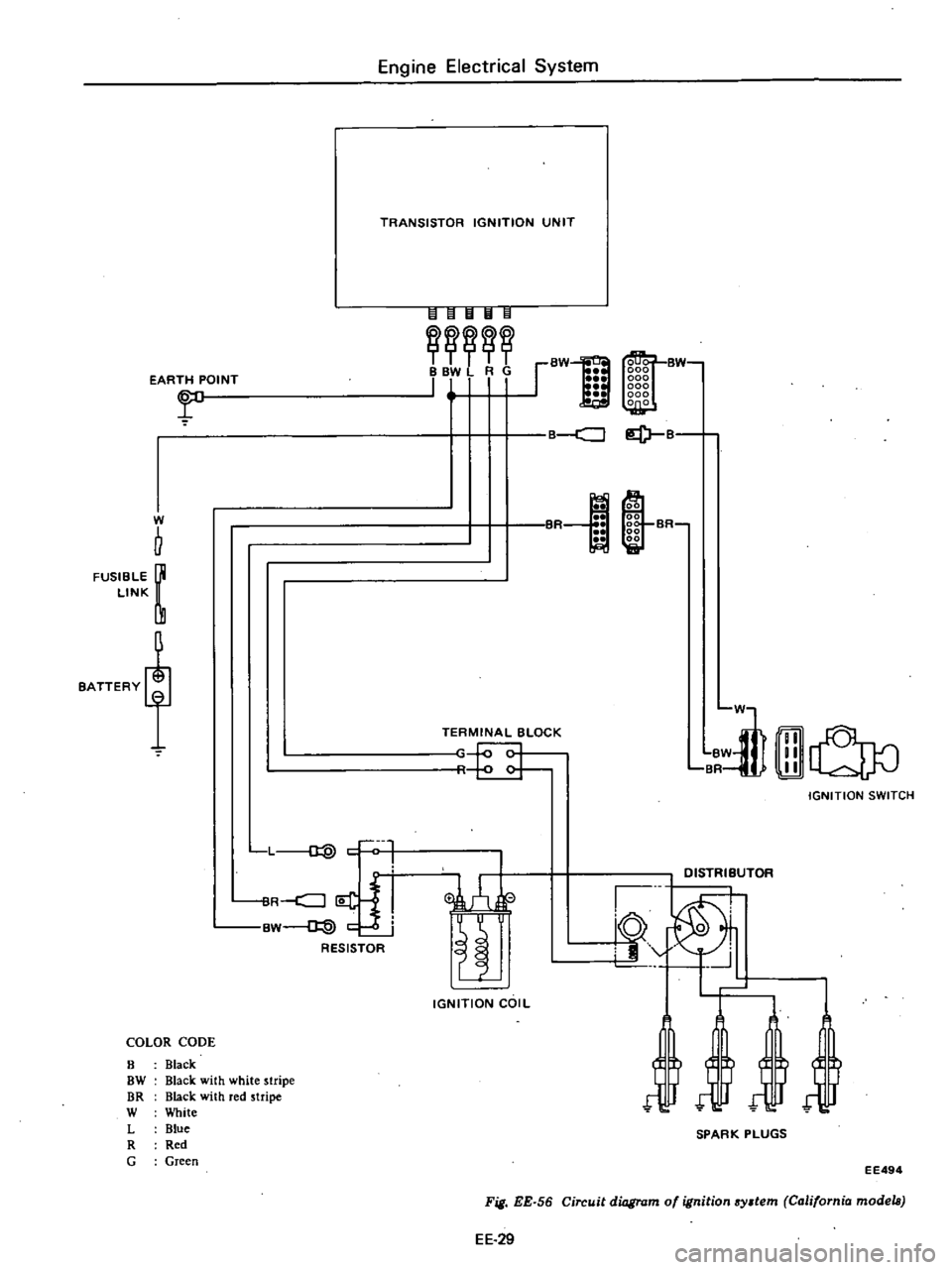
The
ignition
circuit
consists
of
igni
tion
switch
transistor
ignition
unit
distributor
wiring
spark
plugs
and
battery
The
distributor
is
of
the
contactless
type
and
is
equipped
with
a
pick
up
coil
which
electrically
detects
the
igni
tion
timing
signal
in
place
of
the
circuit
breaker
of
the
conventional
distributor
The
transistor
ignition
unit
is
a
new
addition
which
generates
the
signal
required
for
the
make
and
break
of
the
primary
electric
current
for
the
ignition
coil
The
circuit
is
equipped
with
a
resistor
During
cranking
electrical
current
bypasses
the
secondary
resis
tor
thereby
connecting
the
ignition
coil
through
the
primary
resistor
This
makes
battery
voltage
available
at
ef
ficiently
and
keeps
ignition
voltage
as
high
as
possible
The
primary
resistor
selVeS
to
pro
tect
transistor
ignition
circuit
The
low
voltage
current
is
supplied
by
the
battery
or
alternator
and
flows
through
the
primary
circuit
It
consists
of
the
ignition
switch
Engine
Electrical
System
resistor
primary
winding
of
the
igni
tion
coil
transistor
ignition
unit
and
all
connecting
low
tension
wiring
The
high
voltage
current
is
pro
duced
by
the
ignition
coil
and
flows
through
the
secondary
circuit
result
ing
in
high
voltage
spark
between
the
electrodes
of
the
spark
plugs
in
engine
cylinders
This
circuit
contains
the
secondary
winding
of
the
ignition
coil
distribu
tor
high
tension
wires
to
coil
and
spark
plugs
distributor
rotor
and
cap
When
the
ignition
switch
is
turned
on
and
the
distributor
reluctor
rotates
the
primary
current
flows
through
the
primary
winding
of
the
coil
and
through
transistor
ignition
unit
to
ground
When
the
prim
ary
circuit
is
opened
by
circuit
of
transistor
ignition
unit
the
magnetic
field
built
up
in
the
primary
winding
of
the
coil
moves
through
the
secondary
winding
of
the
coil
inducing
high
voltage
This
high
Battery
Primary
Secondary
I
Resistor
To
starter
r
Transis
tor
ignition
unit
I
I
Pick
up
rcoil
r
Rotor
head
nl
J
R5
U1f
1
Retuctor
r
oi
l
f
S
park
plugs
voltage
is
produced
every
time
the
primary
circuit
opens
The
high
voltage
current
flows
through
the
high
tension
wire
to
the
distributor
cap
then
the
rotor
distri
butor
cap
then
the
rotor
distributes
the
current
to
one
of
the
spark
plug
terminals
in
the
distributor
cap
Then
the
spark
occurs
while
the
high
voltage
current
jumps
the
gap
between
the
insulated
electrode
and
the
ground
side
electrode
of
the
spark
plug
This
process
is
repeated
for
each
power
stroke
of
the
engine
The
spark
plug
should
be
inspected
cleaned
and
regapped
at
tune
up
Spark
plugs
should
also
be
replaced
periodically
as
specified
in
the
Main
tenance
Schedule
The
remainder
of
the
ignition
com
ponent
parts
should
be
inspected
for
only
their
operation
air
gap
of
distri
butor
tightness
of
electrical
terminals
and
wiring
condition
Apply
grease
NLGI
consistency
No
I
containing
MoS
or
equivalent
to
distributor
rotor
shaft
as
required
EE287
EE
28
Fig
EE
55
Ignition
8Y3tem
circuit
diagram
Page 196 of 537
EARTH
POINT
r
W
b
FUSIBLE
LINK
BATTERY
L
d
l
ilR
j
i
BW
@
c
RESISTOR
COLOR
CODE
8
Black
OW
Black
with
white
stripe
DR
Black
with
red
stripe
W
White
L
Blue
R
Red
G
Green
Engine
Electrical
System
TRANSISTOR
IGNITION
UNIT
IHIIl
II
II
BW
BBV
RG
111
I
I
TERMINAL
BLOCK
r
c
IGNITION
COIL
BW
B
ml
BR
lliJ
LldJ0
IGNITION
SWITCH
EE
29
Fig
EE
56
Circuit
diagram
of
ignition
system
California
models
EE494
a
B
lof1
@
00
00
00
SR
00
00
Et
liiI
in
D1STRliUTOR
10
0
i9
J
SPARK
PLUGS
Page 199 of 537

DISASSEMBLY
To
disassemble
follow
the
below
proccd
ure
I
Take
off
cap
and
disconnect
rotor
head
2
Remove
vacuum
controller
EE291
Fig
EE
60
Removing
vacuum
controller
3
Remove
contact
set
Refer
to
Page
EE
31
when
contact
set
i
removed
EE323
Fig
EE
61
Removing
contact
tel
EE324
Fig
EE
62
Removing
breaker
plate
Engine
Electrical
System
4
When
breaker
plate
is
removed
be
careful
not
to
lose
steel
balls
between
breaker
spring
and
breaker
plate
5
Pul
roll
pin
out
and
siconnect
collar
to
remove
the
entire
rotating
parts
EE325
Fig
EE
63
Removing
roll
pin
EE326
Fig
EE
64
Removil1l
rotation
paTta
6
Remove
packing
from
the
top
of
cam
assembly
and
unscrew
earn
astern
bly
setscrew
Put
match
mark
across
earn
and
shaft
so
that
original
combi
nation
can
be
restored
at
assembly
EE
32
EE075
Fig
EE
65
Removing
cam
7
When
governor
weight
and
spring
are
disconnected
be
careful
not
to
stretch
or
deform
governor
spring
After
disassembling
apply
grease
to
governor
weights
ASSEMBLY
To
assemble
reverse
the
order
of
disassembly
Carefully
observe
the
fol
lowing
instructions
Align
match
marl
s
so
that
parts
are
assembled
to
their
original
posi
tions
2
Apply
grease
to
the
top
of
cam
assembly
as
required
3
Check
the
operation
of
governor
before
installing
distributor
on
engine
4
Adjust
ignition
timing
afteT
dis
tributor
is
installed
on
engine
Page 200 of 537
Engine
Electrical
System
SERVICE
DATA
AND
SPECIFICATIONS
D4A4
06
D4A4
07
Type
D4A6
07
D4A6
08
Firing
order
1
3
4
2
13
4
2
Rotating
direction
Counterclockwise
Counterclockwise
Owen
angle
degree
490
to
550
490
to
550
Point
gap
mm
in
0
45
to
0
55
0
45
to
0
55
0
018
to
0
022
0
018
to
0
022
Point
pressure
kg
lb
0
40
to
0
55
0
40
to
0
55
0
88
to
1
21
0
88
to
1
21
Condenser
capacity
JlF
0
20
to
0
24
0
20
to
0
24
Condenser
isolate
resistance
Mrl
5
5
Cap
isolate
resistance
Mrl
50
50
Rotor
head
isolate
resistance
Mrl
50
50
Cap
carbon
point
length
mm
in
10
0
39
10
0
39
For
Canada
DISTRIBUTOR
California
models
CONSTRUCTION
CHECKING
AND
ADJUSTMENT
CAP
AND
ROTOR
HEAD
AIR
GAP
CONSTRUCTION
In
the
conventional
distributor
the
ignition
liming
is
detected
by
the
cam
and
breaker
arm
while
in
this
transis
tor
ignition
unit
it
is
detected
by
the
reluctor
on
the
shaft
and
the
pick
up
coil
provided
in
place
of
the
breaker
The
pick
up
coil
consists
of
a
magnet
coil
etc
The
amount
of
magnetic
flux
passing
through
the
pole
piece
in
the
coil
is
changed
at
the
moment
the
pole
CONTENTS
EE
33
EE
33
EE
33
EE
33
ADVANCE
MECHANISMS
DISASSEMBLY
ASSEMBLY
SERVICE
DATA
AND
SPECIFICATIONS
EE
33
EE
35
EE
35
EE
36
piece
faces
the
protrusion
of
the
re
luctor
and
then
the
electrical
signal
is
genera
ted
in
the
pick
up
coil
This
electric
signal
is
conducted
into
the
transistor
ignition
unit
which
in
turn
breaks
tI
e
primary
coil
current
running
through
the
ignition
coil
and
generates
high
voltage
in
the
secondary
winding
Also
this
transistor
ignition
EE
33
unit
utilizes
this
electric
signal
to
restore
the
primary
coil
to
the
original
state
after
cutting
off
the
primary
current
for
a
fIXed
time
The
centrifugal
and
vacuum
ad
vance
mechanisms
employ
the
con
ventional
mechanical
type
The
con
tactor
is
used
to
eliminate
vacuum
and
centrifugal
advance
hysteresis
I
Page 203 of 537
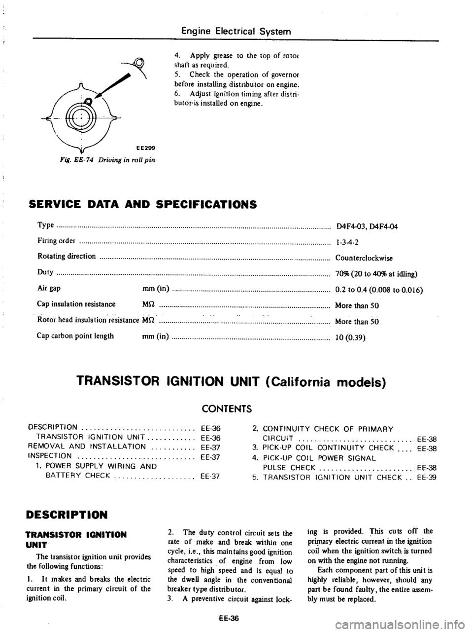
EE299
Fig
EE
74
Driving
in
roll
pin
Engine
Electrical
System
4
Apply
grease
to
the
top
of
rotor
shaft
as
required
5
Check
the
operation
of
governor
before
installing
distributor
on
engine
6
Adjust
ignition
timing
after
distri
butor
is
installed
on
engine
SERVICE
DATA
AND
SPECIFICATIONS
Type
Firing
order
Rotating
direction
Duty
Air
gap
mm
in
MU
Cap
insulation
resistance
Rotor
head
insulation
resistance
MU
Cap
carbon
point
length
mm
in
D4F4
03
D4F4
04
1
3
4
2
Counterclockwise
70
20
to
40
at
idling
0
2
to
0
4
O
OOS
to
0
016
More
than
50
More
than
50
10
0
39
TRANSISTOR
IGNITION
UNIT
California
models
DESCRIPTION
TRANSISTOR
IGNITION
UNIT
REMOVAL
AND
INSTALLATION
INSPECTION
1
POWER
SUPPLY
WI
RING
AND
BATTERY
CHECK
DESCRIPTION
TRANSISTOR
IGNITION
UNIT
The
transistor
ignition
unit
provides
the
following
functions
L
It
makes
and
breaks
the
electric
current
in
the
primacy
circuit
of
the
ignition
coil
2
CONTINUITY
CHECK
OF
PRIMARY
CIRCUIT
3
PICK
UP
COIL
CONTINUITY
CHECK
4
PICK
UP
COIL
POWER
SIGNAL
PULSE
CHECK
5
TRANSISTOR
IGNITION
UNIT
CHECK
CONTENTS
EE
36
EE
36
EE
37
EE
37
EE
37
2
The
duty
control
circuit
sets
the
rate
of
make
and
break
within
one
cycle
i
e
this
maintains
good
ignition
characteristics
of
engine
from
low
speed
to
high
speed
and
is
equal
to
the
dweU
angle
in
the
conventional
breaker
type
distributor
3
A
preventive
circuit
against
lock
EE
36
EE
36
EE
38
EE
38
EE
39
ing
is
provided
This
cuts
off
the
prilnaCY
electric
current
in
the
ignition
coil
when
the
ignition
switch
is
turned
on
with
the
engine
not
running
Each
component
part
of
this
unit
is
highly
reliable
however
should
any
part
be
found
faulty
the
entire
assem
bly
must
be
replaced