ESP DATSUN PICK-UP 1977 Service Manual
[x] Cancel search | Manufacturer: DATSUN, Model Year: 1977, Model line: PICK-UP, Model: DATSUN PICK-UP 1977Pages: 537, PDF Size: 35.48 MB
Page 3 of 537
FOREWORD
This
service
manual
has
been
prepared
for
the
purpose
of
assisting
service
personnel
of
authorized
NISSAN
DATSUN
dealers
fu
providing
effective
service
and
maintenance
of
the
1977
Datsun
Pick
up
Since
proper
maintenance
and
service
are
absolutely
essential
fu
satisfying
the
Datsun
owners
this
inan
la1
should
be
kept
fu
a
handy
place
for
ready
reference
and
should
be
carefuny
studied
This
man
la1
fucludes
procedures
for
ma
futenance
ac
1justrnents
minor
service
operations
remowl
and
installation
and
for
disassembly
and
assembly
of
components
Some
of
these
service
operations
require
the
use
of
Special
Tools
especially
designed
for
effectiveperfonnance
of
service
operations
The
special
tools
are
presented
in
the
SE
section
As
you
read
through
the
maintenance
procedures
in
this
service
manual
you
will
occasionally
corne
across
paragraphs
headed
NOTE
or
CAUTION
A
NOTE
is
supplemental
infortl1ation
that
is
important
to
B
particular
procedure
CAUTION
warns
of
steps
that
must
be
fonowed
to
prevent
personal
injury
and
Qr
damage
to
some
part
of
your
DATSUN
The
Quick
Reference
Index
on
the
first
page
enables
the
user
to
quickly
locate
the
desired
section
At
the
beginning
of
each
individual
section
is
a
table
of
contents
which
gives
the
page
number
on
which
each
major
subject
begins
An
index
is
placed
at
the
beginning
of
each
major
subject
within
the
section
All
information
illustrations
and
specifications
contained
in
this
manual
are
based
on
the
latest
product
information
available
at
the
time
of
publication
approval
If
YOUT
DATSUN
model
differs
from
the
specifications
contained
in
this
manual
consult
your
NlSSAN
DATSUN
dealer
for
information
Rights
for
alteratiohat
any
time
of
specifications
and
methods
are
reserved
liability
for
any
personal
injury
or
property
damage
occasioned
by
the
use
of
this
service
man
la1
in
effecting
maintenance
or
repair
of
your
Datsun
is
in
no
way
assumed
by
Nissan
M9tor
Co
Ltd
Accordingly
anyone
using
a
service
procedure
or
tool
which
is
not
specifically
w
mended
by
Nissan
must
fust
completely
satisfy
himself
that
neither
his
safety
nor
the
vehicle
s
safety
wi11be
jeopardized
by
the
service
method
selected
NISSAN
MOTOR
CO
LTD
TOKYO
JAPAN
@
1976
N1SSAN
MOTOR
CO
LTD
Printed
in
Japan
Page 23 of 537
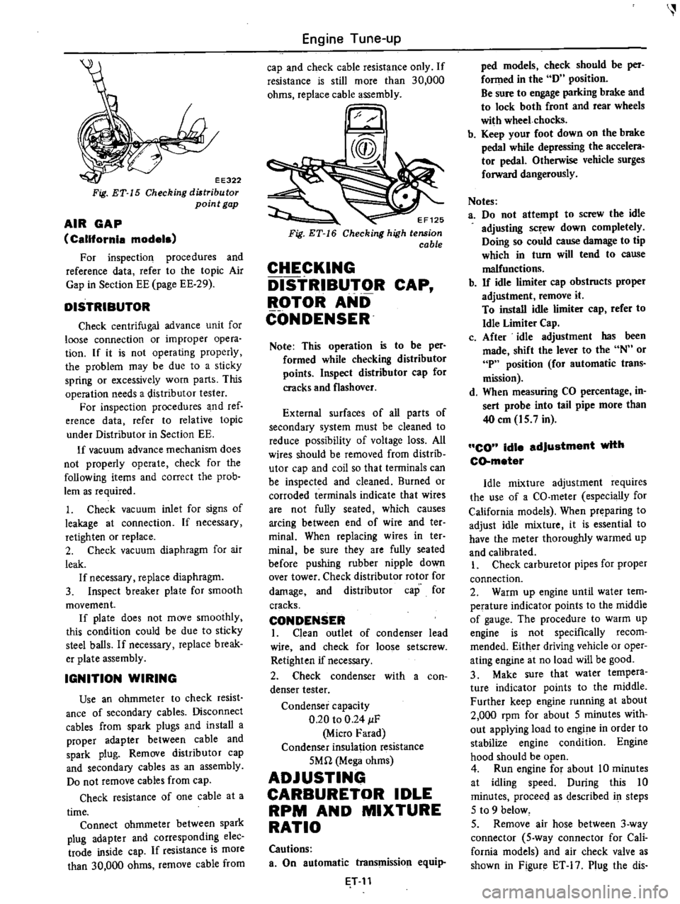
EE322
Fig
ET
15
Checking
diltribu
tor
point
gap
AIR
GAP
California
models
For
inspection
procedures
and
reference
data
refer
to
the
topic
Air
Gap
in
Section
EE
page
EE
29
DISTRIBUTOR
Check
centrifugal
advance
unit
for
loose
connection
or
improper
opera
tion
If
it
is
not
operating
properly
the
problem
may
be
due
to
a
sticky
spring
or
excessively
worn
parts
This
operation
needs
a
distributor
tester
For
inspection
procedures
and
ref
erence
data
refer
to
relative
topic
under
Distributor
in
Section
EE
If
vacuum
advance
mechanism
does
not
properly
operate
check
for
the
following
items
and
correct
the
prob
lem
as
required
1
Check
vacuum
inlet
for
signs
of
leakage
at
connection
If
necessary
retighten
or
replace
2
Check
vacuum
diaphragm
for
air
leak
If
necessary
replace
diaphragm
3
Inspect
breaker
plate
for
smooth
movement
If
plate
does
not
move
smoothly
this
condition
could
be
due
to
sticky
steel
balls
If
necessary
replace
break
er
plate
assembly
IGNITION
WIRING
Use
an
ohmmeter
to
check
resist
ance
of
secondary
cables
Disconnect
cables
from
spark
plugs
and
install
a
proper
adapter
between
cable
and
spark
plug
Remove
distributor
cap
and
secondary
cables
as
an
assembly
Do
not
remove
cables
from
cap
Check
resistance
of
one
cable
at
a
time
Connect
ohmmeter
between
spark
plug
adapter
and
corresponding
elec
trade
inside
cap
If
resistance
is
more
than
30
000
ohms
remove
cable
from
Engine
Tune
up
cap
and
check
cable
resistance
only
If
resistance
is
still
more
than
30
000
ohms
replace
cable
assembly
EF125
Checking
high
tension
cable
CHECKING
DISTRIBUTOR
CAP
ROTOR
AND
CONDENSER
Note
This
operation
is
to
be
per
formed
while
checking
distributor
points
Inspect
distributor
cap
for
cracks
and
flashover
External
surfaces
of
all
parts
of
secondary
system
must
be
cleaned
to
reduce
possibility
of
voltage
loss
All
wires
should
be
removed
from
distrib
utor
cap
and
coil
so
that
terminals
can
be
inspected
and
cleaned
Burned
or
corroded
terminals
indicate
that
wires
are
not
fully
seated
which
causes
arcing
between
end
of
wire
and
ter
minal
When
replacing
wires
in
ter
minai
be
sure
they
are
fully
seated
before
pushing
rubber
nipple
down
over
tower
Check
distributor
rotor
for
damage
and
distributor
cap
for
cracks
CONDENSER
I
Clean
outlet
of
condenser
lead
wire
and
check
for
loose
setscrew
Retighten
if
necessary
2
Check
condenser
with
a
con
denser
tester
Condenser
capacity
0
20
to
0
24
IF
Micro
Farad
Condenser
insulation
resistance
5Mn
Mega
ohms
ADJUSTING
CARBURETOR
IDLE
RPM
AND
MIXTURE
RATIO
Cautions
a
On
automatic
transmission
equip
T
11
ped
models
check
should
be
per
fonned
in
the
D
position
Be
sure
to
engage
parking
brake
and
to
lock
both
front
and
rear
wheels
with
wheel
chocks
b
Keep
your
foot
down
on
the
brake
pedal
while
depressing
the
accelera
tor
pedal
Otherwise
vehicle
surges
forward
dangerously
Notes
a
Do
not
attempt
to
screw
the
idle
adjusting
sc
ew
down
completely
Doing
so
could
cause
damage
to
tip
which
in
turn
will
tend
to
cause
malfunctions
b
If
idle
limiter
cap
obstructs
proper
adjustment
remove
it
To
install
idle
limiter
cap
refer
to
Idle
Limiter
Cap
c
After
idle
adjustment
has
been
made
shift
the
lever
to
the
N
or
P
position
for
automatic
trans
mission
d
When
measuring
CO
percentage
in
sert
probe
into
tail
pipe
more
than
40
em
15
7
in
CO
idle
adjustment
with
CD
meter
Idle
mixture
adjustment
requires
the
use
of
a
CO
meter
especially
for
California
models
When
preparing
to
adjust
idle
mixture
it
is
essential
to
have
the
meter
thoroughly
warmed
up
and
calibrated
I
Check
carburetor
pipes
for
proper
connection
2
Warm
up
engine
until
water
tem
perature
indicator
points
to
the
middle
of
gauge
The
procedure
to
warm
up
engine
is
not
specifically
recom
mended
Either
driving
vehicle
or
oper
ating
engine
at
no
load
will
be
good
3
Make
sure
that
water
tempera
ture
indicator
points
to
the
middle
Further
keep
engine
running
at
about
2
000
rpm
for
about
5
minutes
with
out
applying
load
to
engine
in
order
to
stabilize
engine
condition
Engine
hood
should
be
open
4
Run
engine
for
about
10
minutes
at
idling
speed
During
this
10
minutes
proceeq
as
described
i
steps
5
to
9
below
5
Remove
air
hose
between
3
way
connector
5
way
connector
for
Cali
fornia
models
and
air
check
valve
as
shown
in
Figure
ET
17
Plug
the
dis
Page 30 of 537
r
ADJUSTMENT
OF
SET
PRESSURE
OF
BOOST
CONTROLLED
DECELERATION
DEVICE
B
C
D
D
Generally
it
is
unnecessary
to
ad
just
the
B
C
D
D
however
if
it
should
become
necessary
to
adjust
it
the
procedure
is
as
follows
Prepare
the
foUowlnB
tools
I
Tachometer
to
measure
the
en
gine
speed
while
idling
and
a
screw
driver
2
A
vacuum
gauge
connecting
pipe
Note
A
qui
k
response
type
boost
gauge
such
as
Bourdon
s
type
is
recommended
a
mercury
type
manometer
should
not
be
used
To
properly
set
the
B
C
D
D
set
pressure
proceed
as
follows
I
Remove
the
harness
of
solenoid
valve
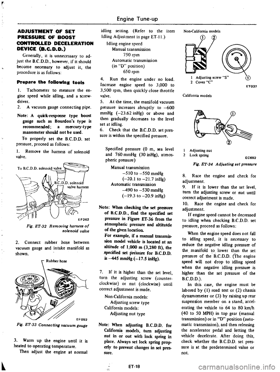
TO
D
D
solenrod
VT
FJ
1
B
C
D
D
solenni
valve
harness
J
ri
y
EF262
F
g
ET
32
Removing
harneS5
of
solenoid
valve
2
Connect
rubber
hose
between
vacuum
gauge
and
intake
manifold
as
shown
Fig
ET
33
Connecting
vacuum
gauge
3
Warm
up
the
engine
until
it
is
heated
to
operating
temperature
Then
adjust
the
engine
at
normal
Engine
Tune
up
idling
setting
Refer
to
the
item
Idling
Adjustment
in
page
ET
II
Idling
engine
speed
Manual
transmission
750
rpm
Automatic
transmission
in
D
position
650
rpm
4
Run
the
engine
under
no
load
Increase
engine
speed
to
3
000
to
3
500
rpm
then
quickly
close
throttle
valve
5
At
the
time
the
manifold
vacuum
pressure
increases
abruptly
to
600
mmHg
23
62
inHg
or
above
and
then
gradually
decreases
to
the
level
set
at
idling
6
Check
that
the
B
C
D
D
set
pres
sure
is
within
the
specified
pressure
Specified
pressure
0
m
sea
level
and
760
mmHg
30
inHg
atmos
pheric
pressure
Manual
transmission
510
to
550
mmHg
20
1
to
21
7
inHg
Automatic
transmission
490
to
530
mmHg
19
3
to
20
9
inHg
Note
When
checking
the
set
pressure
of
B
C
D
D
find
the
specified
set
pressure
in
Figure
IT
36
from
the
atmospheric
pressure
and
altitutde
of
the
given
location
For
example
if
a
manual
transmis
sion
model
vehicle
is
located
at
an
altitude
of
1
000
m
3
280
ft
the
specified
set
preSsure
for
B
C
D
D
445
mmHg
17
5
inHg
7
If
it
is
higher
than
the
set
level
turn
the
adjusting
screw
counter
clockwise
or
nut
clockwise
until
correct
adjustment
is
made
Non
California
models
Adjusting
screw
type
California
models
Adjusting
nut
type
Note
When
adjusting
B
C
D
D
for
California
models
turn
adjusting
nut
in
or
out
with
lock
spring
in
place
Always
set
lock
spring
prop
erly
to
prevent
changes
in
set
pres
sure
ET
18
Non
california
models
1
Adjusting
screw
2
Cover
e
ET037
California
models
r
1
Adjusting
nut
2
Lock
spring
EC692
Fig
ET
34
Adjusting
Bet
pressure
8
Race
the
engine
and
check
for
adjustment
9
If
it
is
lower
than
the
set
level
turn
the
adjusting
screw
or
nut
until
correct
adjustment
is
made
10
Race
the
engine
and
check
for
adjustment
If
engine
speed
cannot
be
decreased
to
idling
when
checking
B
C
D
D
set
pressure
proceed
as
follows
When
the
engine
speed
does
not
fall
to
idling
speed
it
is
necessary
to
reduce
the
negative
idling
pressure
of
the
manifold
to
lower
than
the
set
pressure
of
the
B
C
D
D
The
engine
speed
will
not
drop
to
idling
speed
when
the
negative
idling
pressure
is
higher
than
the
set
pressure
of
the
B
C
D
D
In
this
case
the
engine
must
be
labored
by
I
road
test
or
2
chassis
dynamometer
or
3
by
raising
up
rear
suspension
member
on
a
stand
accel
erating
the
vehicle
to
64
to
80
krn
h
40
to
50
MPH
in
top
gear
manual
transmission
or
in
D
position
auto
matic
transmission
and
then
releasing
the
accelerator
pedal
and
letting
the
vehicle
decelerate
After
doing
this
check
whether
the
B
C
D
D
set
pres
sure
is
at
the
predetermined
value
or
not
Page 34 of 537
r
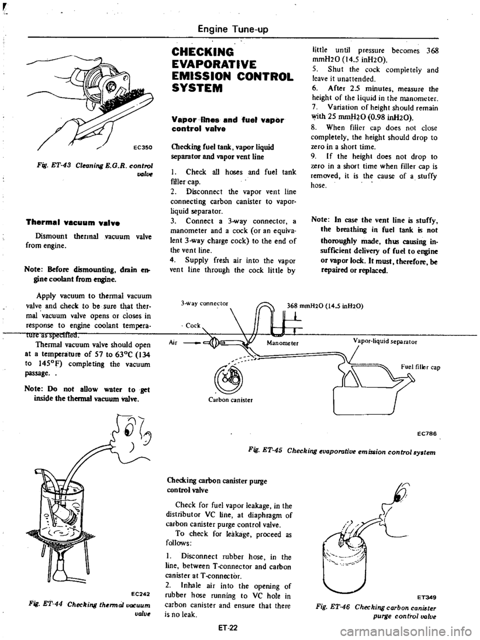
EC350
Fig
ET
43
Cleanill
l
E
G
R
control
lJ
Jlue
Thermal
VBCuum
valve
Dismount
thermal
vacuum
valve
from
engine
Note
Before
dismounting
drain
e
gine
coolant
from
engine
Apply
vacuum
to
thermal
vacuum
valve
and
check
to
be
sure
that
ther
mal
vacuum
valve
opens
or
closes
in
response
to
engine
coolant
tempera
lurt
i1
i
iYCl
lt
lt
U
Thermal
vacuum
valve
should
open
at
a
temperature
of
57
to
630C
134
to
1450F
completing
the
vacuum
passage
Note
Do
not
aUow
water
to
get
inside
the
thermal
vacuum
valve
EC
242
Fig
ET
44
Checkill
lthermallXlCuum
valve
Engine
Tune
up
CHECKING
EVAPORATIVE
EMISSION
CONTROL
SYSTEM
Vapor
Rnes
and
fuel
vepor
control
valve
Checking
fuel
tank
vapor
liquid
separator
and
vapor
vent
line
I
Check
all
hoses
and
fuel
tank
roler
cap
2
Disconnect
the
vapor
vent
line
connecting
carbon
canister
to
vapor
liquid
separator
3
Connect
a
3
way
connector
a
manometer
and
a
cock
or
an
equiva
lent
3
way
charge
cock
to
the
end
of
the
vent
line
4
Supply
fresh
air
into
the
vapor
vent
line
through
the
cock
little
by
little
until
pressure
becomes
368
mmH20
14
5
inH20
5
Shut
the
cock
completely
and
leave
it
unattended
6
After
2
5
minutes
measure
the
height
of
the
liquid
in
the
manometer
7
Variation
of
height
should
remain
with
25
mm
l20
0
98
inH20
8
When
filler
cap
does
not
close
completely
the
height
should
drop
to
zero
in
a
short
time
9
I
f
the
height
does
not
drop
to
zero
in
a
short
time
when
filler
cap
is
removed
it
is
the
cause
of
a
stuffy
hose
Note
In
case
the
vent
line
is
stuffy
the
breathing
in
fuel
tank
is
not
thoroughly
made
thl
causing
in
suffICient
delivery
of
fuel
to
engine
or
vapor
lock
It
must
therefore
be
repaired
or
replaced
3
way
connectoT
36
mmH20
14
5
inH20
c
s
I
W
@
Carbon
canister
r
EC786
Fig
ET
45
Checking
evaporative
emission
control
By
tem
Checking
carbon
canister
purge
control
valve
Check
for
fuel
vapor
leakage
in
the
distributor
VC
line
at
diaphragm
of
carhon
canister
purge
control
valve
To
check
for
leakage
proceed
as
follows
1
Disconnect
rubber
hose
in
the
line
between
T
connector
and
carbon
canister
at
T
connector
2
Inhale
air
into
the
opening
of
rubber
hose
running
to
VC
hole
in
carbon
canister
and
ensure
that
there
is
no
leak
ET
22
I
I
L
I
ET349
Fig
ET
46
Checking
carbon
cani
ter
purge
control
valve
Page 55 of 537
rr
ROCKER
ARM
AND
VALVE
ROCKER
PIVOT
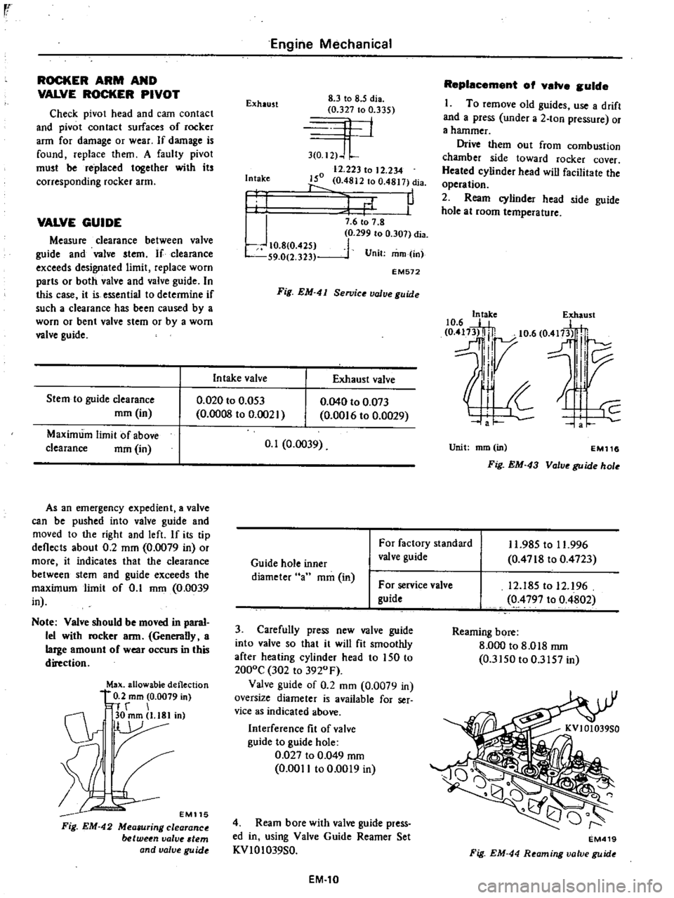
Check
pivot
head
and
cam
contact
and
pivot
contact
surfaces
of
rocker
arm
for
damage
or
wear
If
damage
is
found
replace
them
A
faulty
pivot
must
be
replaced
together
with
its
corresponding
rocker
arm
VALVE
GUIDE
Measure
clearance
between
valve
guide
and
valve
stem
If
clearance
exceeds
designated
limit
replace
worn
parts
or
both
valve
and
valve
guide
In
this
case
it
is
essential
to
determine
if
such
a
clearance
has
been
caused
by
a
worn
or
bent
valve
stem
or
by
a
worn
valve
guide
Stem
to
guide
clearance
mm
in
Maximum
limit
of
above
clearance
mm
in
Engine
Mechanical
Exhaust
8
3
to
8
5
dia
0
327
to
0
335
4
1
3
0
I2
J
L
12
223
to
12
234
150
0
4812
to
0
4817
dia
1
P
Intake
I
I
J
10
8
0
425
S9
0
2
323
7
6
to
7
8
0
299
to
0
307
dia
1
Unit
mm
in
EM572
Fig
EM
41
Se11Jice
value
guide
In
take
valve
Exhaust
valve
0
020
to
0
053
0
0008
to
0
002
As
an
emergency
expedient
a
valve
can
be
pushed
into
valve
guide
and
moved
to
the
right
and
left
If
its
tip
deflects
about
0
2
mm
0
0079
in
or
more
it
indicates
that
the
clearance
between
stem
and
guide
exceeds
the
maximum
limit
of
0
1
mm
0
0039
in
Note
Valve
should
be
moved
in
paral
lel
with
rocker
arm
Generally
a
large
amount
of
wear
occurs
in
this
direction
Max
allowable
deflection
0
2
mm
0
0079
in
n
r
C1r
30mm
l
18Iin
r
EM115
Fig
EM
42
Mea
uring
clearance
between
valve
tern
and
valve
gu
ide
0
040
to
0
073
0
00
6
to
0
0029
0
1
0
0039
Replacement
of
valve
guide
I
To
remove
old
guides
use
a
drift
and
a
press
under
a
2
ton
pressure
or
a
hammer
Drive
them
out
from
combustion
chamber
side
toward
rocker
cover
Heated
cylinder
head
will
facilitate
the
operation
2
Ream
cylinder
head
side
guide
hole
at
room
temperature
10
6
E
e
417
5t
0
m3l
lj
10
6
O
fl
H
dl7
l
IV
II
Unit
mm
in
EM116
Fig
EM
43
Valve
guide
hole
Guide
hole
inner
diameter
an
mm
in
For
factory
standard
valve
guide
11
985
to
11
996
0
4718
to
0
4723
For
service
valve
guide
3
Carefully
press
new
valve
guide
into
valve
so
that
it
will
fit
smoothly
after
heating
cylinder
head
to
150
to
2000C
302
to
3920
F
Valve
guide
of
0
2
mm
0
0079
in
oversize
diameter
is
available
for
ser
vice
as
indicated
above
Interference
fit
of
valve
guide
to
guide
hole
0
027
to
0
049
mm
0
0011
to
0
0019
in
4
Ream
bore
with
valve
guide
press
ed
in
using
Valve
Guide
Reamer
Set
KVIOI039S0
EM
10
12
185
to
12
96
0
4797
to
0
4802
Reaming
bore
8
000
to
8
018
rnm
0
3150
to
0
3157
in
EM419
Fig
EM
44
Reaming
valve
guide
Page 61 of 537
r
Piston
pin
outside
diameter
Piston
pin
hole
diameter
Piston
pin
to
piston
clearance
I
Interference
fit
of
piston
pin
to
connecting
rod
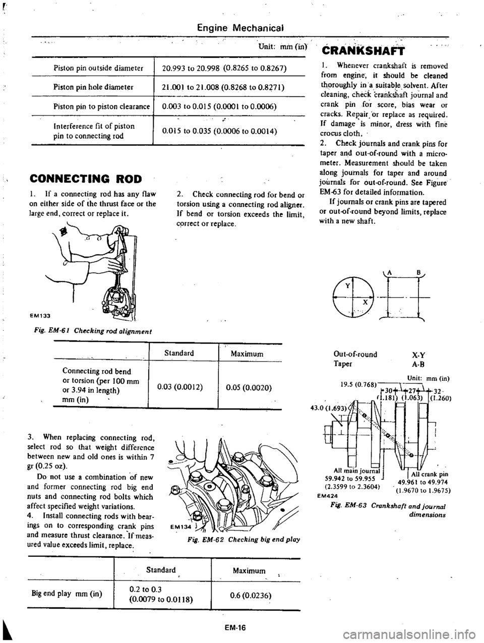
CONNECTING
ROD
I
If
a
connecting
rod
has
any
flaw
on
either
side
of
the
thrust
face
or
the
large
end
correct
or
replace
it
EM133
Fig
EM
61
Ch
cking
rod
alignment
Connecting
rod
bend
or
torsion
per
100
mm
or
3
94
in
length
mm
in
3
When
replacing
connecting
rod
select
rod
so
that
weight
difference
between
new
and
old
ones
is
within
7
gr
0
25
oz
Do
not
use
a
combination
of
new
and
former
connecting
rod
big
end
nuts
and
connecting
rod
bolts
which
affect
specified
weight
variations
4
Install
connecting
rods
with
bear
ings
on
to
corresponding
crank
pins
and
measure
thrust
clearance
Ifmeas
ured
value
exceeds
limit
replace
Engine
Mechanical
Unit
mm
in
20
993
to
20
998
0
8265
to
0
8267
21
001
to
21
008
0
8268
to
0
8271
0
003
to
0
015
0
0001
to
0
006
0
015
to
0
035
0
0006
to
0
0014
2
Check
connecting
rod
for
bend
or
torsion
using
a
connecting
rod
aligner
If
bend
or
torsion
exceeds
the
limit
q
rrect
or
replace
Standard
Maximum
0
03
0
0012
0
05
0
0020
Fig
EM
62
Checking
big
end
play
Standard
Maximum
Big
end
play
mm
in
0
2
to
0
3
0
0079
to
0
01
18
0
6
0
0236
EM
16
CRANKSHAFT
1
Whenever
crankshaft
is
removed
from
engine
it
should
be
cleaned
thoroughly
in
a
suitable
solvent
After
cleaning
check
crankshaft
journal
and
crank
pin
Jor
score
bias
wear
or
cracks
Rep
air
or
replace
as
required
If
damage
is
minor
dress
with
fine
crocus
cloth
2
Check
journals
and
crank
pins
for
taper
and
out
of
round
with
a
micro
meter
Measurement
should
be
taken
along
journals
for
taper
and
around
journals
for
out
of
round
See
Figure
EM
63
for
detailed
information
If
journals
or
crank
pins
are
tapered
or
out
of
round
beyond
limits
replace
with
a
new
shaft
A
B
Out
of
round
X
Y
Taper
A
B
Unit
mm
in
19
5
0
768
tt
30
27
32
181
1
06
1
260
43
O
l
69
I
E
1
All
main
journa
59
942
to
59
955
All
crank
pm
2
3599
l
2
3604
49
961
to
49
974
o
1
9670
to
1
9675
EM424
Fig
EM
63
Crankshaft
and
journal
dimensions
Page 66 of 537
PRECAUTIONS
CYLINDER
HEAD
PRECAUTIONS
I
Use
thoroughly
cleaned
parts
Especially
make
sure
that
oil
holes
are
clear
of
foreign
matter
2
When
installing
sliding
parts
such
as
bearings
be
s
uIe
to
apply
engine
oil
to
them
3
Use
new
packing
and
oil
seals
4
Do
not
reuse
lock
washers
5
Keep
tools
and
work
benches
clean
6
Keep
necessary
parts
and
tools
near
at
hand
7
Be
sure
to
follow
specified
tight
ening
torque
and
order
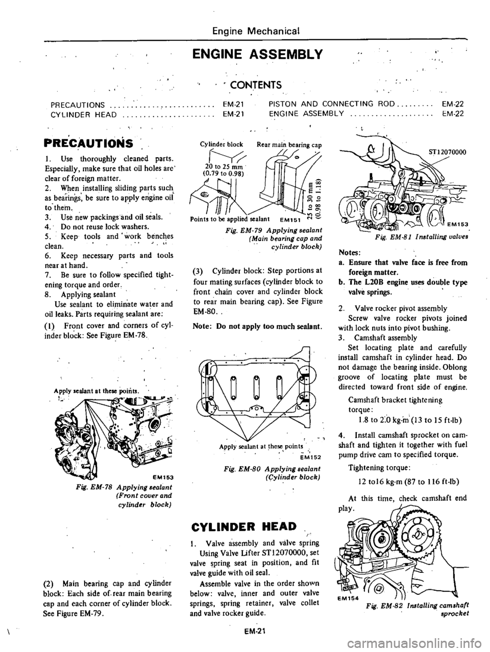
8
Applying
sealant
Use
sealant
to
eliminate
water
and
oil
leaks
Parts
requiring
sealant
are
I
Front
cover
and
corners
of
cyl
inder
block
See
Figure
EM
78
EM153
Fig
EM
78
Applying
alant
Front
cover
and
cylinder
block
2
Main
bearing
cap
and
cylinder
block
Each
side
of
rear
main
bearing
cap
and
each
corner
of
cylinder
block
See
Figure
EM
79
Engine
Mechanical
ENGINE
ASSEMBLY
CONTENTS
EM
21
EM
21
PISTON
AND
CONNECTING
ROD
ENGINE
ASSEMBLY
EM
22
EM
22
Cylinder
block
Rear
main
bearing
cap
20to2Smm
Ill
Points
to
be
applied
sealant
EM151
s
e
00
000
o
Fig
EM
79
Applying
sealanl
Main
bearing
cap
and
cylinder
block
3
Cylinder
block
Step
portions
at
four
mating
surfaces
cylinder
block
to
front
chain
cover
and
cylinder
block
to
rear
main
bearing
cap
See
Figure
EM
80
Note
Do
not
apply
too
much
sealant
J
Apply
sealant
at
hese
points
EM152
Fig
EM
80
Applying
sealant
Cylinder
block
CYLINDER
HEAD
Valve
assembly
and
valve
spring
Using
Valve
Lifter
STl2070000
set
valve
pring
seat
in
position
and
fit
valve
guide
with
oil
seaL
Assemble
valve
in
the
order
shown
below
valve
inner
and
outer
valve
springs
spring
retainer
valve
collet
and
valve
rocker
guide
EM
21
Fig
EM
81
Installing
valves
Notes
a
Ensure
that
valve
face
is
free
from
foreign
matter
b
The
L20B
engine
uses
double
type
valve
springs
2
Valve
rocker
pivot
assembly
Screw
valve
rocker
pivots
joined
with
lock
nuts
into
pivot
hushing
3
Camshaft
assembly
Set
locating
plate
and
carefully
install
camshaft
in
cylinder
head
Do
not
damage
the
bearing
inside
Oblong
groove
of
locating
plate
must
be
directed
toward
front
side
of
engine
Camshaft
bracket
tightening
torque
1
8
to
2
0
kg
in
13
to
15
ft
lb
4
Install
camshaft
sprocket
on
earn
shaft
and
tighten
it
together
with
fuel
pump
drive
cam
to
specified
torque
Tightening
torque
12
tol6
kg
m
87
to
116
ft
lb
this
time
check
camshaft
end
Fig
EM
82
Installing
camshaft
sprocket
Page 68 of 537
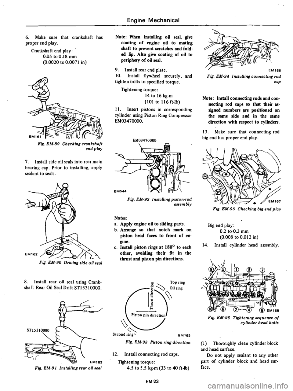
6
Make
sure
that
crankshaft
has
proper
end
play
Crankshaft
end
play
0
05
to
0
18
mm
0
0020
to
0
0071
in
Fig
EM
89
Checking
crankshaft
end
play
7
Install
side
oil
seals
into
rear
main
bearing
cap
Prior
to
installing
apply
sealant
to
seals
Fig
EM
90
Driving
side
oil
seal
8
Install
rear
oil
seal
using
Crank
shaft
Rear
Oil
Seal
Drift
STI5310000
r
STl5310000
r
EM163
Fig
EM
91
Installing
rear
oi
seal
Engine
Mechanical
Note
When
installing
oil
seal
give
coating
of
engine
oil
to
mating
shaft
to
prevent
scratches
and
fold
ed
lip
Also
give
coating
of
oil
to
periphery
of
oil
seal
9
Install
rear
end
plate
10
Install
flywheel
securely
and
tighten
bolts
to
specified
torque
Tightening
torque
14
to
16
kg
m
101
to
116
ft
lb
I
I
Insert
pistons
in
corresponding
cylinder
using
Piston
Ring
Compressor
EM03470000
EM03410000
I
EM544
Fig
EM
92
Installing
pi8ton
rod
a
Sembly
Notes
a
Apply
engine
oil
to
sliding
parts
b
Arrange
80
that
notch
mark
on
piston
head
faces
to
front
of
en
gine
c
Install
piston
rings
at
1800
to
each
other
avoiding
their
fit
in
the
thrust
and
piston
pin
directions
6
Top
ring
I
iilring
Piston
pin
ireClioJ
EM165
Fig
EM
93
PUtan
ring
direction
12
Install
connecting
rod
caps
Tightening
torque
4
5
to
5
5
kg
m
33
to
40
ft
lb
EM
23
Fig
EM
94
Installing
connecting
rod
cap
Note
Install
connecting
rods
and
con
necting
rod
caps
80
that
their
as
signed
numbers
are
positioned
on
the
same
side
and
in
the
SlIme
direction
with
respect
to
cylinders
13
Make
sure
that
connecting
rod
big
end
has
proper
end
play
Fig
EM
95
Checking
big
end
play
Big
end
play
0
2
to
0
3
mm
0
008
to
0
Ql2
in
14
Install
cylinder
head
assembly
Fig
EM
96
Tightening
sequence
01
cylinder
head
bolts
J
Thoroughly
clean
cylinder
block
and
head
surface
Do
not
apply
sealant
to
any
other
part
of
cylinder
block
and
head
sur
face
Page 98 of 537
Engine
Fuel
AUTOMATIC
TEMPERATURE
CONTROL
A
T
C
AIR
CLEANER
DESCRIPTION
OPERATION
A
T
C
AIR
CLEANER
HOT
AIR
OPERATION
A
T
C
AIR
CLEANER
COLD
AIR
OPERATION
A
T
C
AIR
CLEANER
COLD
AND
HOT
AIR
OPERATION
TEMPERATURE
SENSOR
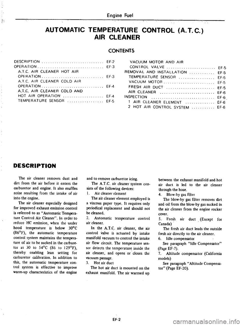
DESCRIPTION
The
air
cleaner
removes
dust
and
dirt
from
the
air
before
it
enters
the
carburetor
and
engine
It
also
muffles
noise
resulting
from
the
intake
of
air
into
the
engine
The
air
cleaner
especially
designed
for
improved
exhaust
emission
control
is
referred
to
as
Automatic
Tempera
ture
Control
Air
Cleaner
In
order
to
reduce
HC
emission
when
the
under
hood
temperature
is
below
300C
860F
the
automatic
temperature
control
system
maintains
the
tempera
ture
of
air
to
be
sucked
in
the
carbure
tor
at
30
to
540C
86
to
1290F
thereby
enabling
lean
setting
for
carburetor
calibration
n
addition
to
this
the
automatic
temperature
con
twl
system
is
effective
to
improve
warm
up
characteristics
of
the
engine
CONTENTS
EF
2
EF
3
VACUUM
MOTOR
AND
AIR
CONTROL
VALVE
REMOVAL
AND
INSTALLATION
TEMPERATURE
SENSOR
VACUUM
MOTOR
FRESH
AIR
DUCT
AIR
CLEANER
INSPECTION
1
AIR
CLEANER
ELEMENT
2
HOT
AIR
CONTROL
SYSTEM
EF
3
EF
4
EF
4
EF
5
and
to
remove
carburetor
icing
The
A
T
C
air
cleaner
system
con
sists
of
the
following
devices
1
Air
cleaner
element
The
air
cleaner
element
employed
is
a
viscous
paper
type
It
requires
only
periodical
replacment
and
should
not
be
cleaned
2
Automatic
temperature
control
air
cleaner
In
the
A
T
C
air
cleaner
the
air
control
valve
is
actuated
by
intake
manifold
vacuum
to
control
the
intake
air
flow
circuit
The
temperature
sen
sor
detects
the
temperature
inside
the
air
cleaner
and
opens
or
closes
the
vacuum
passage
3
Hot
air
duct
The
hot
air
duct
is
mounted
on
the
exhaust
manifold
The
air
warmed
up
EF
2
EF
5
EF
5
EF
5
EF
5
EF
5
EF
6
EF
6
EF
6
EF
6
between
the
exhaust
manifold
and
hot
air
duct
is
led
to
the
air
cleaner
through
the
hose
4
Blow
by
gas
filter
The
blow
by
gas
nIter
removes
dirt
and
oil
from
the
blow
by
gas
sucked
in
the
air
cleaner
from
the
engine
rocker
cover
5
Fresh
air
duct
Except
for
Canada
The
fresh
air
duct
leads
the
outside
fresh
air
directly
to
the
air
cleaner
6
Idle
compensator
See
paragraph
Idle
Compensator
Page
EF
7
7
Altitude
compensator
California
models
See
paragraph
Altitude
Compensa
tor
Page
EF
20
Page 100 of 537
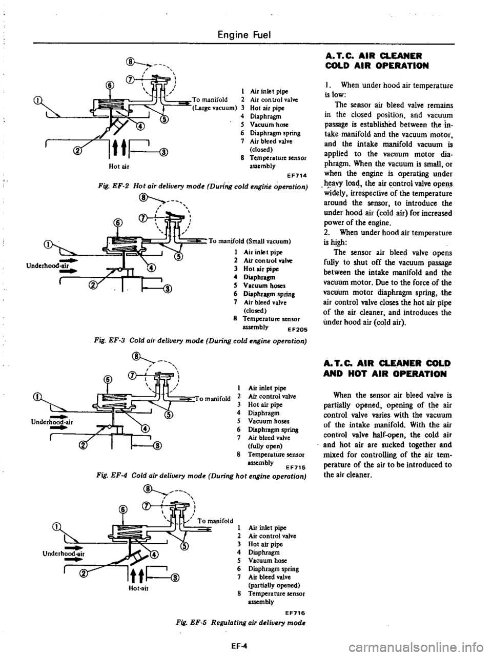
Underhood
air
I
@
Dr
Underhood
air
I
Engine
Fuel
f
f
l
l
ID
s
6
Cif
Ittl
ID
Air
inlet
pipe
Air
con
trol
valve
Hot
air
pipe
Diaphragm
Vacuum
hose
Diaphragm
spring
Air
bleed
valve
closed
Temperature
sensor
assembly
Holair
EF114
Fig
EF
2
Hota
r
delivery
mode
During
cold
engine
operation
7
To
manifold
Small
vacuum
1
Air
inlet
pipe
2
Air
con
trol
valw
3
Hot
air
pipe
4
Diaphnp
S
V
leuum
hoses
6
Diaphragm
prinl
7
Air
bleed
valve
closed
II
Temperature
senSOr
assembly
EF20S
Fig
EF
3
Cold
air
delivery
mode
During
cold
engine
operation
f
1
J
liP
omanifold
2
@
Air
inlet
pipe
Air
control
valve
Hot
air
pipe
Diaphragm
Vacuum
hoses
Diaphragm
spring
Air
bleed
valve
fully
open
8
Temperature
sensor
assembly
EF715
Fig
EF
4
Cold
air
delivery
mode
During
hot
engine
operation
ID
@
f
fjr
R
lfl
ow
2
underh
r
5
rv
Itti
ID
Hot
air
Air
inlet
pipe
Air
control
valve
Hot
air
pipe
Diaphragm
Vacuum
hose
Diaphragm
spring
Air
bleed
valve
partially
opened
8
Temperature
sensor
assembly
EF716
Fig
EF
5
Regulating
air
delivery
mode
EF
4
A
T
C
AIR
CLEANER
COLD
AIR
OPERATION
I
When
under
hood
air
temperature
is
low
The
sensor
air
bleed
valve
remains
in
the
closed
position
and
vacuum
passage
is
established
between
the
in
take
manifold
and
the
vacuum
motor
and
the
intake
manifold
vacuum
is
applied
to
the
vacuum
motor
dia
phragm
When
the
vacuum
is
small
or
when
the
engine
is
operating
under
eavy
1004
the
air
control
valve
opens
widely
irrespective
of
the
temperature
around
the
sensor
to
introduce
the
under
hood
air
cold
air
for
increased
power
of
the
engine
2
When
under
hood
air
temperature
is
high
The
sensor
air
bleed
valve
opens
fully
to
shut
off
the
vacuum
passage
between
the
intake
manifold
and
the
vacuum
motor
Due
to
the
force
of
the
vacuum
motor
diaphragm
spring
the
air
control
valve
closes
the
hot
air
pipe
of
the
air
cleaner
and
introduces
the
under
hood
air
cold
air
A
T
C
AIR
CLEANER
COLD
AND
HOT
AIR
OPERATION
When
the
sensor
air
bleed
valve
is
partially
opened
opening
of
the
air
control
valve
varies
with
the
vacuum
of
the
intake
manifold
With
the
air
control
valve
half
open
the
cold
air
and
hot
air
are
sucked
together
and
mixed
for
controlling
of
the
air
tem
perature
of
the
air
to
be
introduced
to
the
air
cleaner