ESP DATSUN PICK-UP 1977 Owner's Guide
[x] Cancel search | Manufacturer: DATSUN, Model Year: 1977, Model line: PICK-UP, Model: DATSUN PICK-UP 1977Pages: 537, PDF Size: 35.48 MB
Page 317 of 537
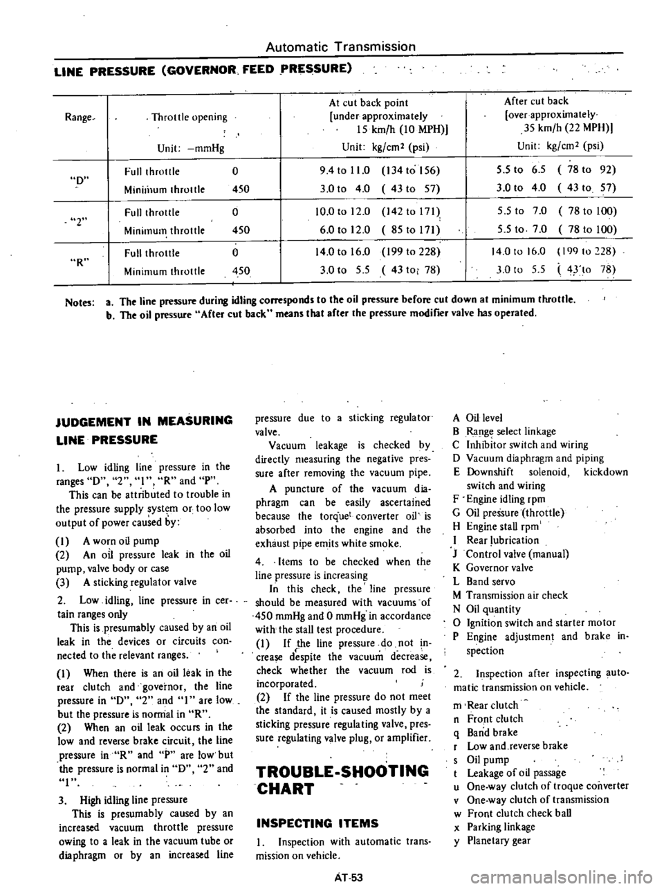
Automatic
Transmission
LINE
PRESSURE
GOVERNOR
FEED
PRESSURE
At
cut
back
point
After
cut
back
Throttle
opening
under
approximately
over
approximately
15
kmfh
10
MPH
35
kmfh
22
MPH
Unit
mmHg
Unit
kgfcm2
psi
Unit
kgfcm2
psi
Full
throtlle
0
9
4
to
11
0
134
to
156
5
5
to
6
5
78
to
92
Minill1um
throttle
450
3
0
to
4
0
43to
57
3
0
to
4
0
43
to
57
Fulllhrotlle
0
10
0
to
12
0
142
to
171
5
5
to
7
0
78
to
100
Minimum
throttle
450
6
0
to
12
0
85to171
5
5
to
7
0
78
to
100
Full
throtlle
0
14
0
to
16
0
199
to
228
14
0
to
16
0
199
to
228
Minimum
throttle
450
3
0
to
5
5
43
to
78
3
0
to
5
5
4
lo
78
Range
D
2
R
Notes
a
The
line
pressure
during
idling
corresponds
to
the
oil
pressure
before
cut
down
at
minimum
throttle
b
The
oil
pressure
After
cut
back
means
that
after
the
pressure
modifier
valve
has
operated
JUDGEMENT
IN
MEASURING
LINE
PRESSURE
Low
idling
line
pressure
in
the
ranges
D
2
I
R
and
pH
This
can
be
atlributed
to
trouble
in
the
pressure
supply
system
or
too
low
output
of
power
caused
by
I
A
worn
oil
pump
2
An
oil
pressure
leak
in
the
oil
pump
valve
body
or
case
3
A
sticking
regulator
valve
2
Low
idling
line
pressure
in
cer
tain
ranges
only
This
is
presumably
caused
by
an
oil
leak
in
the
devices
or
circuits
con
nected
to
the
relevant
ranges
I
When
there
is
an
oil
leak
in
the
rear
clutch
and
governor
the
line
pressure
in
D
2
and
I
are
low
but
the
pressure
is
norrrial
in
R
2
When
an
oil
leak
occurs
in
the
low
and
reverse
brake
circuit
the
line
pressure
in
R
and
P
are
low
but
the
pressure
is
normal
in
D
2
and
I
3
High
idling
line
pressure
This
is
presumably
caused
by
an
increased
vacuum
throttle
pressure
owing
to
a
leak
in
the
vacuum
tube
or
dia
phragm
or
by
an
increased
line
pressure
due
to
a
sticking
regulator
valve
Vacuum
leakage
is
checked
by
directly
measuring
the
negative
pres
sure
after
removing
the
vacuum
pipe
A
puncture
of
the
vacuum
dia
phragm
can
be
easily
ascertained
because
the
torque
converter
oil
is
absorbed
into
the
engine
and
the
exhaust
pipe
emits
white
smoke
4
Items
to
be
checked
when
the
line
pressure
is
increasing
In
this
check
the
line
pressure
should
be
measured
with
vacuums
of
450
mmHg
and
0
mmHg
in
accordance
with
the
stall
test
procedure
I
If
the
line
pressure
do
not
n
crease
despite
the
vacuum
decrease
check
whether
the
vacuum
rod
is
incorporated
2
If
the
line
pressure
do
not
meet
the
standard
it
is
caused
mostly
by
a
sticking
pressure
regulating
valve
pres
sure
regulating
valve
plug
or
amplifier
TROUBLE
SHOOTING
CHART
INSPECTING
ITEMS
1
Inspection
with
automatic
trans
mission
on
vehicle
AT
53
A
Oil
level
B
Ra
lge
select
linkage
C
Inhibitor
switch
and
wiring
D
Vacuum
diaphragm
and
piping
E
Downshift
solenoid
kickdown
switch
and
wiring
F
Engine
idling
rpm
G
Oil
pressure
throttle
H
Engine
stall
rpm
I
Rear
lubrication
J
Control
valve
manual
K
Governor
valve
L
Band
servo
M
Transmission
air
check
N
Oil
quantity
o
Ignition
switch
and
starter
motor
P
Engine
adjustment
and
brake
in
spection
2
Inspection
after
inspecting
auto
matic
transmission
on
vehicle
m
Rear
clutch
n
Front
clutch
q
Band
brake
r
Low
and
reverse
brake
s
Oil
pump
t
Leakage
of
oil
passage
u
One
way
clutch
of
troque
coilVerter
v
One
way
clutch
of
transmission
w
Front
clutch
check
ball
x
Parking
linkage
y
Planetary
gear
Page 363 of 537
Front
Axle
Front
Suspension
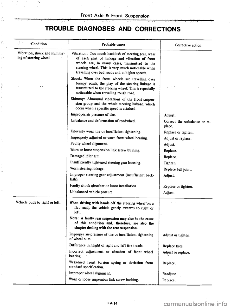
TROUBLE
DIAGNOSES
AND
CORRECTIONS
Condition
Vibration
shock
and
shimmy
ing
of
steering
wheeL
Vehicle
pulls
to
right
or
left
Probable
cause
Vibration
Too
much
backlash
of
steering
gear
wear
of
each
part
of
linkage
and
vibration
of
front
wheels
are
in
many
cases
transmitted
to
the
steering
wheel
This
is
Very
much
noticeable
when
traveJling
over
bad
roads
and
at
higher
speeds
Shock
When
the
front
wheels
are
travelling
over
bumpy
roads
the
play
of
the
steering
linkage
is
transmitted
to
the
steering
wheel
This
is
especially
noticeable
when
travelling
rough
road
Shimmy
Abnormal
vibrations
of
the
front
suspen
sion
group
and
the
whole
steering
linkage
which
occur
when
a
specific
speed
is
attained
Improper
air
pressure
of
tire
Unbalance
and
deformation
of
roadwheel
Unevenly
worn
tire
or
insufficient
tightening
Improperly
adjusted
or
worn
front
wheel
bearing
Faulty
wheel
alignment
Worn
or
loose
suspension
link
screw
bushing
Damaged
idler
arm
Insufficiently
tightened
steering
gear
housing
Worn
steering
linkage
Improper
steering
gear
adjustment
insufficient
back
lash
Faulty
shock
absorber
or
loose
installation
Unbalanced
vehicle
posture
When
driving
with
hands
off
the
steering
wheel
on
a
fiat
road
the
vehicle
gently
swerves
to
right
or
left
Note
A
faulty
rear
suspension
may
also
be
the
cause
of
this
condition
and
therefore
see
also
the
chapter
dealing
with
the
rear
suspension
Improper
air
pressure
of
tire
or
insufficient
tightening
of
wheel
nu
ts
Difference
in
height
of
right
and
left
tire
treads
Incorrect
adjustment
or
abrasion
of
front
wheel
bearing
Weakened
front
torsion
spring
or
deviation
from
standard
specification
Improper
wheel
alignment
Worn
or
loose
suspension
link
screw
bushing
FA
14
Corrective
action
Adjust
Correct
the
unbalance
or
re
place
Replace
or
tighten
Adjust
or
replace
Adjust
Replace
Replace
TIghten
Replace
ball
joint
Adjust
Replace
or
tighten
Adjust
Adjust
or
tighten
Replace
tires
Adjust
or
replace
Replace
Readjust
Replace
Page 384 of 537
After
connecting
brake
tube
be
sure
to
check
the
clearance
to
prevent
from
damage
The
clearance
at
the
following
portions
must
be
specified
distance
or
more
Tube
to
body
panel
and
frame
Over
5
mm
0
20
in
Tube
to
edge
of
each
panel
Over
10
mm
0
39
in
Tube
to
tube
Loop
pitch
OVer
5
mm
0
20
in
Between
front
tube
and
rear
tube
Over
9
mOl
0
35
in
Tube
to
moving
parts
Over
10
mm
0
39
in
Loop
tube
to
hood
ledge
panel
Over
10
mm
0
39
in
Notes
a
Brake
tubes
are
shaped
at
factory
to
secure
specified
clearance
and
may
not
require
reshaping
Discard
if
they
call
for
excessive
reshaping
b
In
reshaping
a
brake
tube
take
care
to
avoid
damaging
galvanization
or
collapsing
section
Mter
brake
lines
have
been
asssem
bled
check
to
make
sure
that
all
fittings
and
flare
nu
Is
ale
lightened
to
correct
torques
Tightenint
torque
Brake
tube
to
connector
I
Ston
kg
m
II
to
13
ft
Ib
Brake
tube
to
brake
hose
1
7
to
2
0
kg
m
12
to
14
ft
lb
Connector
and
clip
fixing
bolt
O
3S
to
O
4S
kg
m
2
5
to
3
3
ft
lb
3
way
connector
fixing
bolt
on
rear
axle
case
0
8
to
1
1
kg
m
6
to
8
ft
lb
N
L
S
V
DESCRIPTION
The
Nissan
Load
Sensing
Valve
N
L
S
V
serves
to
change
braking
power
of
the
rear
wheels
in
response
to
changes
in
the
load
and
fluid
pressure
improving
braking
stability
and
shortening
stopping
distances
Brake
System
The
N
L
S
V
is
installed
on
the
frame
being
inclined
at
10
degrees
A
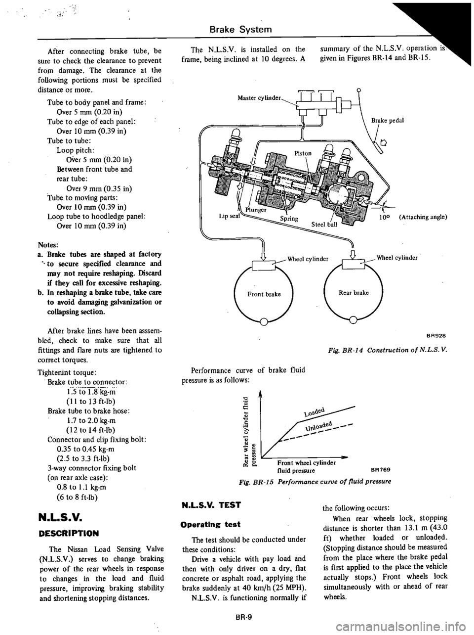
summary
of
the
N
L
S
v
operation
is
given
in
Figures
BR
14
and
BR
15
r
Master
cylinder
TI
II
I
y
1
J
I
l
Attaching
angle
D
Wheel
cylinder
BR928
Fig
BR
14
Construction
of
N
L
S
V
Performance
curve
of
brake
fluid
pressure
is
as
follows
0
S
c
A
0
C
o
l
0
oadea
U1U
Front
wheel
cylinder
fluid
pressure
BR769
Perfonnance
curve
of
fluid
pressure
Fig
BR
15
N
L
S
V
TEST
the
following
occurs
When
rear
wheels
lock
stopping
distance
is
shorter
than
13
1
m
43
0
ft
whether
loaded
or
unloaded
Stopping
distance
should
be
measured
from
the
place
where
the
brake
pedal
is
first
applied
to
the
place
the
vehicle
actually
stops
Front
wheels
lock
simultaneously
with
or
ahead
of
rear
wheels
Operating
test
The
test
should
be
conducted
under
these
conditions
Drive
a
vehicle
with
pay
load
and
then
with
only
driver
on
a
dry
flat
concrete
or
asphalt
road
applying
the
brake
suddenly
at
40
km
h
25
MPH
N
L
S
V
is
functioning
normally
if
BR
9
Page 385 of 537
Ibove
mentioned
st
is
available
when
op
the
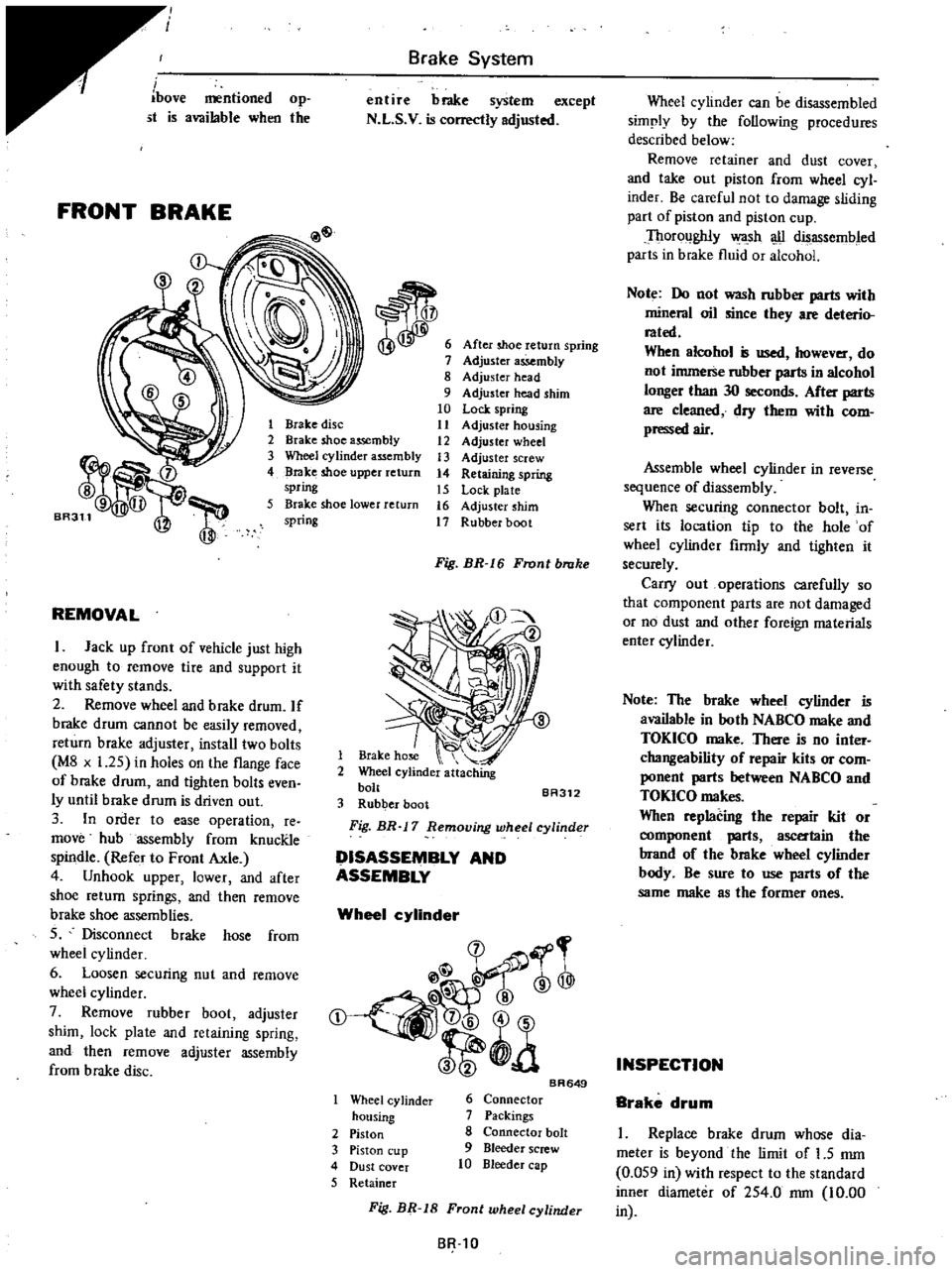
FRONT
BRAKE
Brake
System
entire
brake
system
except
N
L
S
V
is
correctly
adjusted
After
shoe
return
spring
Adjuster
assembly
8
Adjuster
head
9
Adjuster
head
shim
10
Lock
spring
11
Adjuster
housing
12
Adjuster
wheel
13
Adjuster
screw
14
Retaining
spring
15
Lock
plate
16
Adjuster
shim
17
Rubber
boot
1
Brake
disc
2
Brake
shoe
assembly
3
Wheel
cylinder
assembly
4
Brake
shoe
upper
return
spring
5
Brake
shoe
lower
return
spring
REMOVAL
I
Jack
up
front
of
vehicle
just
high
enough
to
remove
tire
and
support
it
with
safety
stands
2
Remove
wheel
and
brake
drum
If
brake
drum
cannot
be
easily
removed
return
brake
adjuster
install
two
bolts
M8
x
1
25
in
holes
on
the
flange
face
of
brake
drum
and
tighten
bolts
even
ly
until
brake
drum
is
driven
out
3
In
order
to
ease
operation
re
move
hub
assembly
from
knucRle
spindle
Refer
to
Front
Axle
4
Unhook
upper
lower
and
after
shoe
return
springs
and
then
remove
brake
shoe
assemblies
S
Disconnect
brake
hose
from
wheel
cy
linder
6
Loosen
securing
nut
and
remove
wheel
cylinder
7
Remove
rubber
boot
adjuster
shim
lock
plate
and
retaining
spring
and
then
remove
adjuster
assembly
from
brake
disc
Fig
BR
I
6
Front
brake
1
Brake
hose
2
Wheel
cylinder
attaching
bolt
BA312
3
Rubber
boot
Fig
BR
17
Removing
wheel
cylinder
DISASSEMBLY
AND
ASSEMBLY
Wheel
cylinder
@
rr
l
@
t
a
Wheel
cy
linder
housing
2
Piston
3
Piston
cup
4
Dust
cover
5
Retainer
BR649
6
Connector
7
Packings
8
Connector
bolt
9
Bleeder
screw
10
Bleeder
cap
Wheel
cylinder
can
be
disassembled
simply
by
the
following
procedures
described
below
Remove
retainer
and
dust
cover
and
take
out
piston
from
wheel
cyl
inder
Be
careful
not
to
damage
sliding
part
of
piston
and
piston
cup
Thoroughly
wa
sh
u
disassembled
parts
in
brake
fluid
or
alcohol
Note
Do
not
wash
rubber
parts
with
mineral
oil
since
they
are
deterio
rated
When
alcohol
is
used
however
do
not
immerse
rubber
parts
in
alcohol
longer
than
30
seconds
After
parts
are
cleaned
dry
them
with
com
pressed
air
Assemble
wheel
cylinder
in
reverse
sequence
of
diassembly
When
securing
connector
bolt
in
sert
its
location
tip
to
the
hole
of
wheel
cylinder
firmly
and
tighten
it
securely
Carry
out
operations
carefully
so
that
component
parts
are
not
damaged
or
no
dust
and
other
foreign
materials
enter
cylinder
Note
The
brake
wheel
cylinder
is
available
in
both
NABCO
make
and
TOKICO
make
There
is
no
inter
changeability
of
repair
kits
or
com
ponent
parts
between
NABCO
and
TOKICO
makes
When
replacing
the
repair
kit
or
ent
parts
ascertain
the
brand
of
the
brake
wheel
cylinder
body
Be
sure
to
use
parts
of
the
same
make
as
the
former
ones
INSPECTION
Brake
drum
I
Replace
brake
drum
whose
dia
meter
is
beyond
the
limit
of
1
5
mm
0
OS9
in
with
respect
to
the
standard
inner
diameter
of
2S4
0
rom
10
00
SR
tO
Fig
BR
18
Front
wheel
cylinder
in
Page 390 of 537
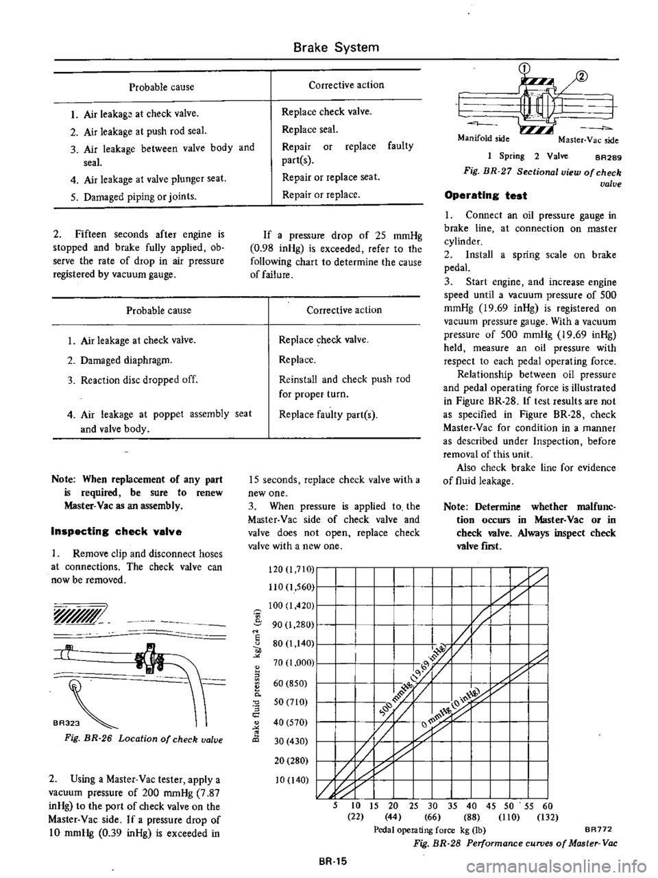
Probable
cause
I
Air
leakago
at
check
valve
2
Air
leakage
a
t
push
rod
seal
3
Air
leakage
between
valve
body
and
seal
4
Air
leakage
at
valve
plunger
seat
5
Damaged
piping
or
joints
2
Fifteen
seconds
after
engine
is
stopped
and
brake
fully
applied
ob
serve
the
rate
of
drop
in
air
pressure
registered
by
vacuum
gauge
Probable
cause
1
Air
leakage
at
check
valve
2
Damaged
diaphragm
3
Reaction
disc
dropped
off
4
Air
leakage
at
and
valve
body
poppet
assembly
seat
Note
When
replacement
of
any
part
is
required
be
sure
to
renew
Master
Vac
as
an
assembly
Inspecting
check
valve
Remove
clip
and
disconnect
hoses
at
connections
The
check
valve
can
now
be
removed
yr
BA3
Fig
BR
26
Location
of
check
valve
2
Using
a
Master
Vac
tester
apply
a
vacuum
pressure
of
200
mmHg
7
87
inHg
to
the
port
of
check
valve
on
the
Master
Vac
side
If
a
pressure
drop
of
10
mmHg
0
39
inHg
is
exceeded
in
1
I
I
17
I
f
I
I
I
Z
I
I
y1
I
I
I
7
I
I
I
I
I
I
I
I
I
I
y1
II
I
I
I
I
I
I
I
L
I
L
5
to
15
20
25
30
35
40
45
50
55
60
22
44
66
88
110
132
Pedal
operating
force
kg
lb
BR772
Fig
BR
28
Performance
curves
of
Master
Vac
Brake
System
Corrective
action
Replace
check
valve
Replace
seal
Repair
or
replace
faulty
partes
Repair
or
replace
seat
Repair
or
replace
If
a
pressure
drop
of
25
mmHg
0
98
inHg
is
exceeded
refer
to
the
following
chart
to
determine
the
cause
of
failure
Corrective
action
Replace
check
valve
Replace
Reinstall
and
check
push
rod
for
proper
turn
Replace
faulty
part
s
15
seconds
replace
check
valve
with
a
new
one
3
When
pressure
is
applied
to
the
Master
Vac
side
of
check
valve
and
valve
does
not
open
replace
check
valve
with
a
new
one
120
I
7IG
110
1
560
100
I
420
i
90
1
280
I
u
80
1
140
70
1
000
II
60
850
0
0
5
a
50
710
40
570
30
430
20
280
10
140
BR
15
1
I
Manifold
side
Master
Yac
side
1
Spring
2
Valve
BA289
Fig
BR
27
Sectional
view
of
check
valve
Operating
test
1
Connect
an
oil
pressure
gauge
in
brake
line
at
connection
on
master
cylinder
2
Install
a
spring
scale
on
brake
pedal
3
Start
engine
and
increase
engine
speed
until
a
vacuum
pressure
of
500
mmHg
19
69
inHg
is
registered
on
vacuum
pressure
gauge
With
a
vacuum
pressure
of
500
mmHg
19
69
inHg
held
measure
an
oil
pressure
with
respect
to
each
pedal
operating
force
Relationship
between
oil
pressure
and
pedal
operating
force
is
illustrated
in
Figure
BR
28
If
test
results
are
not
as
specified
in
Figure
BR
28
check
Master
Vac
for
condition
in
a
manner
as
described
under
Inspection
before
removal
of
this
unit
Also
check
brake
line
for
evidence
of
fluid
leakage
Note
Determine
whether
malfunc
tion
occurs
in
Master
Vac
or
in
check
valve
Always
inspect
check
valve
fiTlit
Page 407 of 537
STEERING
SYSTEM
STEERING
CONTENTS
DESCRIPTION
STEERING
GEAR
Remo
al
and
installation
Disassembly
and
assembly
ST
2
ST
3
ST
3
ST
4
Inspection
and
repair
STEERING
LINKAGE
Removal
and
installation
Inspection
and
repair
ST
5
ST
6
ST
6
ST
7
DESCRIPTION
The
other
end
of
the
cross
rod
is
linked
to
the
idler
arm
connecting
with
the
side
member
located
on
the
opposite
side
of
the
steering
gear
The
two
side
rods
serve
to
connect
the
steering
gear
arm
and
idler
arm
to
the
both
knuckle
arms
right
and
left
hand
sides
With
this
construction
even
if
the
left
andlor
right
wheel
moves
vertical
The
steering
gear
used
on
this
model
series
vehicles
is
e
same
re
circulating
type
This
steering
gear
is
designed
especially
for
easy
operation
and
high
durability
The
steering
linkage
is
of
a
relay
design
of
which
gear
arm
is
connected
to
one
end
of
the
adjustable
cross
rod
ly
and
independently
steering
can
be
safely
maintained
Steering
wheel
rotation
is
converted
to
gear
arm
motion
in
proportion
to
the
gear
ratio
by
the
steering
gear
The
gear
arm
motion
operates
the
side
rod
on
the
same
side
At
the
same
time
the
idler
arm
is
moved
through
the
cross
rod
and
the
opposite
side
rod
is
also
moved
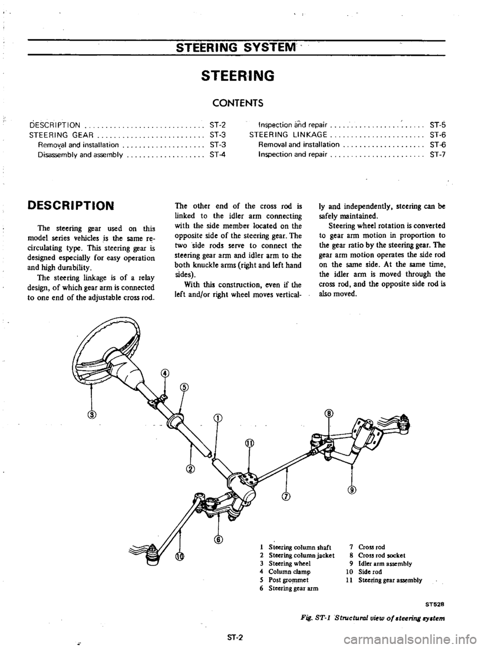
1
Steering
column
shaft
2
Steering
column
jacket
3
Steering
wheel
4
Column
clamp
S
Post
gro
llmet
6
Steering
gear
arm
sr
2
7
Cross
rod
8
Cross
rod
socket
9
Idler
arm
assembly
10
Side
rod
11
Steering
gear
assembly
ST528
Fig
ST
I
Structural
u
w
of
teeriTl
l
tem
Page 412 of 537
I
J
L6
3
4
5
1
Apply
recommended
grease
to
screw
bushing
interior
plain
bushing
interior
dust
seal
inside
and
bushing
sliding
surface
of
idler
ann
Screw
bushing
tightening
torque
12
kg
m
87
ft
lb
2
Before
installing
idler
arm
assem
bly
replace
f
iller
plug
with
grease
nipple
and
apply
recommended
grease
to
idler
ann
through
this
grease
nipple
until
grease
is
forced
out
at
the
lower
end
of
the
dust
seal
lip
Remove
grease
I
8
I
II
I
I
FIODt
Inspection
and
repair
Ball
joint
1
When
ball
stud
is
worn
or
axial
play
is
too
excessive
replace
cross
rod
socket
or
side
rod
with
a
new
one
2
When
dust
cover
is
broken
or
defonned
be
sure
to
replace
with
a
new
one
Axial
end
play
0
1
to
0
5
mm
0
004
to
0
020
in
Initial
swing
torque
S
to
15
kg
cm
70
to
209
in
oz
STEERING
SYSTEM
nipple
and
reinstall
filler
plug
3
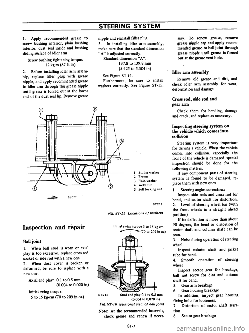
In
installing
idler
arm
assembly
make
sure
that
the
standard
dimension
A
is
adjusted
correctly
Standard
dimension
A
137
8
to
139
8
mm
S
42S
to
S
504
in
See
Figure
ST
14
Furthermore
be
sure
to
install
washers
correctly
See
Figure
ST
IS
Spring
washer
Frame
Plain
washer
Weld
nut
Self
locking
nut
ST212
Fig
ST
15
Locations
of
washers
Initial
swing
torque
5
to
15
kg
cm
70
to
209
in
oz
ST213
ST
7
sary
To
renew
grease
remove
grease
nipple
cap
and
apply
recom
mended
grease
to
ball
joint
through
grease
nipple
until
grease
is
forced
out
at
the
grease
vent
hole
Idler
arm
3B8embly
Remove
old
grease
and
dirt
and
check
idler
ann
assembly
for
wear
deformation
and
damage
CrOBS
rod
side
rod
and
gear
arm
Check
them
for
bending
damage
and
crack
and
replace
as
necessary
Inspecting
steering
system
on
the
vehicle
which
comes
into
collision
Steering
system
is
very
important
for
driving
a
vehicle
When
the
vehicle
comes
into
collision
especially
the
front
of
the
vehicle
is
damaged
special
inspection
should
be
done
for
the
following
matters
If
any
component
parts
of
steering
system
is
found
to
be
damaged
re
place
them
with
new
ones
1
Steering
angles
correctness
Inspect
side
rods
and
cross
rod
for
bend
and
sector
shaft
for
distortion
2
Level
of
steering
wheel
bar
with
the
front
wheels
in
a
straight
ahead
position
If
its
deflection
is
more
than
about
90
degrees
the
bend
or
distortion
of
sector
shaft
and
column
shaft
can
be
seen
3
Noise
during
operation
of
steering
wheel
Inspect
column
shaft
and
jacket
tube
for
bend
4
Smooth
operation
of
steering
wheel
Inspect
sector
gear
for
breakage
ball
nut
screw
for
dint
and
column
shaft
for
bend
S
Gear
arm
breakage
6
Gear
housing
breakage
In
addition
inspect
gear
housing
f
IXing
bolts
for
looseness
7
Distortion
of
sector
shaft
serra
tion
8
Sector
gear
breakage
Page 451 of 537
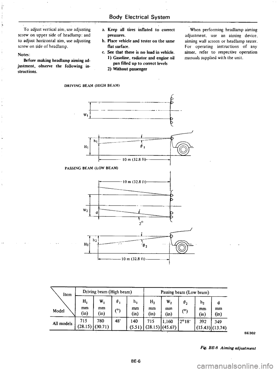
To
adjust
vertical
aim
use
adjusting
screw
on
upper
side
of
headlamp
and
to
adjust
horizontal
aim
use
adjusting
screw
on
side
of
head
lamp
Notes
Before
making
headlarnp
aiming
ad
justment
observe
the
foUowing
in
structions
Body
Electrical
System
a
Keep
aU
tires
inflated
to
correct
pressures
b
Place
vehicle
and
tester
on
the
same
flat
surface
c
See
that
there
is
no
load
in
vehicle
I
Gasoline
radiator
and
engine
oil
pan
filled
up
to
correct
levels
2
Without
passenger
When
performing
headlamp
aiming
adjustment
use
an
aiming
device
aiming
wall
screen
or
headlamp
tester
For
operating
instructions
of
any
aimer
refer
to
respective
operation
manuals
supplied
with
the
unit
DRIVING
BEAM
HIGH
BEAM
L
wt
H
G
hi
i
iiI
PASSING
BEAM
LOW
BEAM
10
m
32
8
ft
W2
H2
10
m
02
8
n
d
20
h2
I
02
I
I
f
10
m
32
8
ft
Driving
beam
High
beam
Passing
beam
Low
beam
HI
WI
01
mm
mm
CO
in
in
I
715
780
48
All
models
28
15
30
71
hI
H2
W2
h2
O2
d
mm
mm
mm
in
in
in
0
140
I
715
11
160
12018
5
51
28
15
45
67
mm
mm
in
in
392
349
is
43
13
74
BE302
Fig
BE
8
Aiming
adjustment
BE
6
Page 463 of 537
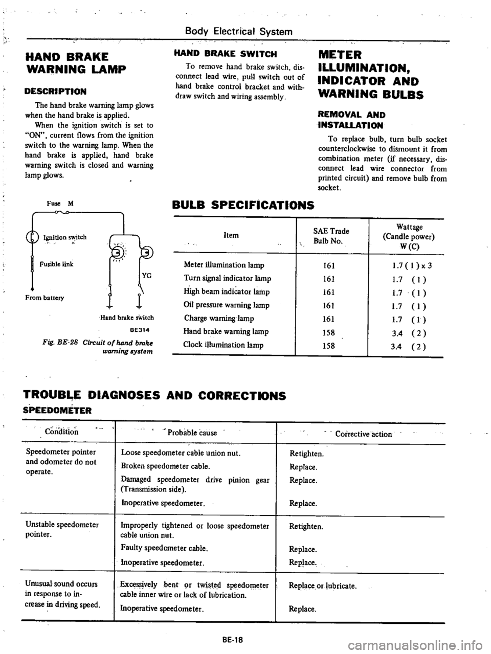
HAND
BRAKE
WARNING
LAMP
DESCRIPTION
The
hand
brake
warning
lamp
glows
when
the
hand
brake
is
applied
When
the
ignition
switch
is
set
to
ON
current
flows
from
the
ignition
switch
to
the
warning
lamp
When
the
hand
brake
is
applied
hand
brake
warning
switch
is
closed
and
warning
lamp
glows
Fuse
M
Ignition
5
tch
Fusible
link
From
battery
I
YG
1
1
Hand
brake
sWitch
BE314
Fig
BE
28
Circuit
of
hand
broke
warning
Iystem
Body
Electrical
System
HAND
BRAKE
SWITCH
To
remove
hand
brake
switch
dis
connect
lead
wire
pull
switch
out
of
hand
brake
control
bracket
and
with
draw
switch
and
wiring
assembly
METER
ILLUMINATION
INDICATOR
AND
WARNING
BULBS
REMOVAL
AND
INSTALLATION
To
replace
bulb
turn
bulb
socket
counterclockwise
to
dismount
it
from
combination
meter
if
necessary
dis
connect
lead
wire
connector
from
printed
circuit
and
remove
bulb
from
socket
BULB
SPECIFICATIONS
Item
Meter
illumination
lamp
Turn
signal
indicator
lamp
High
beam
indicator
lamp
Oil
pressure
warning
lamp
Charge
warning
lamp
Hand
brake
warning
lamp
Clock
illumination
lamp
SAE
Trade
Bulb
No
Wattage
Candle
power
W
e
161
161
161
161
161
158
158
1
7
I
x3
1
7
I
1
7
I
I
7
I
1
7
I
3
4
2
3
4
2
TROUB
E
DIAGNOSES
AND
CORRECTIONS
SPEEDOMETER
Condition
Speedometer
pointer
and
odometer
do
not
operate
Unstable
speedometer
pointer
Unusual
sound
occurs
in
response
to
in
crease
in
driving
speed
Probable
cause
Loose
speedometer
cable
union
nut
Broken
speedometer
cable
Damaged
speedometer
drive
pinion
gear
Transmission
side
Inoperative
speedometer
Improperly
tightened
or
loose
speedometer
cable
union
nut
Faulty
speedometer
cable
Inoperative
speedometer
ExceS
jvelybent
or
twisted
speedOmeter
cable
inner
wire
or
lack
of
lubrication
Inoperative
speedometer
8El8
Coirective
action
Retighten
Replace
Replace
Replace
Retighten
Replace
Replace
Replace
or
lubricate
Replace
Page 498 of 537
Water
in
the
system
will
ice
the
orifice
when
the
high
pressure
re
frigerant
is
changed
to
low
pressure
refrigerant
by
expansion
valve
etc
and
will
obstruct
the
refrigerant
flow
The
following
items
are
general
instructions
to
be
closely
observed
in
servicing
the
system
I
When
a
system
line
is
discon
nected
plug
the
opening
immediately
This
is
especially
necessary
to
prevent
moisture
condensation
from
forming
in
the
line
and
to
keep
out
dirt
and
dust
It
is
also
necessary
to
keep
the
line
at
and
above
surrounding
air
temperatures
at
all
times
When
con
necting
system
lines
do
not
attempt
to
remove
the
plug
from
the
opening
until
ready
for
immediate
use
2
Always
keep
the
working
place
clean
and
dry
and
free
from
dirt
and
dust
Wipe
water
off
with
a
clean
cloth
3
Have
all
necessary
tools
in
pre
paration
beforehand
and
have
tools
clean
and
dry
4
The
compressor
oil
will
easily
absorb
moisture
when
exposed
to
air
Immediateiy
close
the
opening
of
the
container
after
use
It
is
also
necessary
to
observe
the
following
notes
Notes
a
The
oil
should
not
be
transfused
from
a
container
into
another
as
the
failure
will
possibly
cause
mois
ture
to
mix
with
the
oil
b
The
used
oil
should
not
be
returned
into
a
container
c
The
oil
should
not
be
used
if
its
state
of
preservation
is
not
clear
enough
5
When
connecting
or
disconnect
ing
pipes
from
the
refrigeration
sys
tem
use
two
wrenches
One
wrench
is
used
for
holding
the
fixing
nut
in
place
while
the
other
for
turning
the
mating
flare
nut
Failure
to
do
so
may
result
in
a
twisted
tube
or
may
damage
connection
6
Also
use
care
not
to
give
scratches
to
the
seating
surface
at
connections
A
small
scratch
on
the
seating
surface
Air
Conditioning
may
be
the
cause
of
gas
leakage
Before
connecting
pipes
be
sure
to
give
coating
of
compressor
oil
to
the
sea
ting
surfaces
SAFETY
PRECAUTIONS
I
Since
direct
contact
of
the
liquid
refrigerant
with
your
skin
will
cause
frostbite
always
be
careful
when
handling
the
refrigerant
Wear
gloves
or
wrap
a
piece
of
cloth
around
service
valve
to
protect
your
fingers
against
frostbite
by
refrigerant
If
any
of
the
refrigerant
should
get
into
your
eyes
when
charging
the
refrigerant
splash
your
eyes
with
cool
water
to
raise
the
temperature
gradually
Apply
a
protec
tive
film
to
the
eye
to
avoid
infection
Do
not
rub
your
eyes
Consult
an
eye
specialist
Always
wear
goggles
or
glasses
to
protect
your
eyes
when
working
around
the
system
Should
refrigerant
strikes
your
body
splash
on
cool
water
and
apply
a
protective
film
2
The
refrigerant
service
container
has
a
safe
strength
However
if
han
dled
incorrectiy
it
wili
explode
Therefore
always
follow
the
instruc
tions
on
the
label
In
particular
never
stpre
it
in
a
hot
location
above
S20C
l250F
or
drop
it
from
a
high
height
3
The
refrigerant
gas
is
odorless
and
colorless
and
breathing
may
become
difficult
due
to
the
lack
of
oxygen
Since
the
refrigerant
gas
is
heavier
than
air
and
will
lay
close
to
the
floor
be
especially
careful
when
handling
it
in
small
confined
spaces
4
The
refrigerant
itself
is
nonflam
mable
However
a
toxic
gas
phosgene
gas
is
produced
when
it
contacts
fire
and
special
care
is
therefore
required
when
checking
for
leaks
in
the
system
with
a
halide
torch
5
Do
not
steam
clean
on
the
sys
tern
especially
condenser
since
exces
sively
high
pressure
will
build
up
in
the
system
resulting
in
explosion
of
the
system
The
above
precautions
are
essential
in
handling
of
Refrigerant
l
2
and
their
strict
observation
requires
suffi
AC
9
dent
training
Therefore
it
is
of
first
importance
that
any
other
personnel
than
a
well
trained
serviceman
should
not
be
allowed
to
handle
the
refrig
erant
EVACUATING
AND
CHARGING
SYSTEM
During
servicing
use
caution
to
keep
air
from
getting
into
refrigerant
When
air
enters
the
system
all
refriger
ant
must
be
evacuated
from
system
prior
to
charging
new
refrigerant
Air
in
refrigerant
has
the
following
delete
rious
effects
I
Since
the
condensation
tempera
ture
of
the
air
is
extremely
low
the
air
will
not
be
condensed
when
refrigerant
gas
is
condensed
in
the
condenser
and
the
air
will
thus
remain
in
gaseous
form
Consequently
the
effective
thermal
transmission
area
of
condenser
for
refrigerant
gas
will
be
red
uced
and
refrigerant
gas
to
be
condensed
will
be
red
ueed
The
pressure
rise
will
become
proportional
to
the
volume
of
the
air
in
system
2
When
air
and
refrigerant
are
mixed
in
system
a
chemical
reaction
will
be
produced
and
hydrochloric
acid
which
will
adversely
affect
the
aluminum
copper
iron
and
other
materials
in
system
may
be
generated
HANDLING
MANIFOLD
GAUGE
The
pressure
at
the
high
and
low
sides
of
system
should
be
measured
when
evacuating
and
charging
refrig
erant
and
when
diagnosing
trouble
in
the
system
The
manifold
gauge
is
used
for
these
purposes
A
manifold
gauge
has
two
pressure
gauges
a
low
pressure
gauge
and
a
high
pressure
gauge
These
gauges
are
connected
to
the
high
and
low
side
service
valves
of
system
through
flexible
charging
hoses
The
construction
of
manifold
gauge
is
shown
in
Figure
AC
13
When
valve
stem
is
fully
screwed
the
valve
is
front
seated
and
valve
path
and
the
center
path
are
blocked
When
valve
stem
is
backed
off
the
paths
are
opened