boot DATSUN PICK-UP 1977 Service Manual
[x] Cancel search | Manufacturer: DATSUN, Model Year: 1977, Model line: PICK-UP, Model: DATSUN PICK-UP 1977Pages: 537, PDF Size: 35.48 MB
Page 214 of 537
DESCRIPTION
INSPECTION
CLEANING
AND
REGAP
DESCRIPTION
The
spark
plugs
are
of
the
conven
tional
type
having
14
mm
0
551
in
threads
The
spark
plug
gaps
are
1
0
to
1
1
mm
0
039
to
0
043
in
on
Cali
fomia
models
and
0
8
to
0
9
mm
0
031
to
0
035
in
on
non
California
models
The
inspection
and
cleaning
should
be
made
every
suitable
mainte
nance
period
If
necessary
replace
Note
All
spark
plugs
installed
on
an
engine
must
be
of
the
same
brand
and
the
same
number
of
heat
range
INSPECTION
L
Remove
spark
plug
wire
by
pulling
on
boot
not
on
wire
itself
2
Remove
spark
plugs
3
Check
electrodes
and
inner
and
outer
porcelains
of
plugs
noting
the
type
of
deposits
and
the
degree
of
electrode
erosion
Refer
to
Figure
EE
96
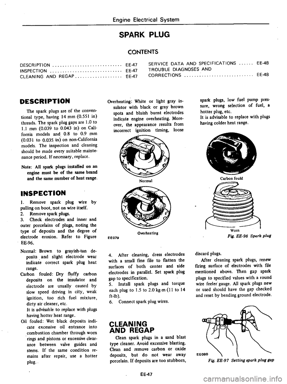
Normal
Brown
to
grayish
tan
de
posits
and
slight
electrode
wear
indicate
correct
spark
plug
heat
range
Carbon
fouled
Dry
fluffy
carbon
deposits
on
the
insulator
and
electrode
are
usually
caused
by
slow
speed
driving
in
city
weak
ignition
too
rich
fuel
mixture
dirty
air
cleaner
etc
It
is
advisable
to
replace
with
plugs
having
hotter
heat
range
Oil
fouled
Wet
black
deposits
indi
cate
excessive
oil
entrance
into
combustion
chamber
through
worn
rings
and
pistons
or
excessive
clear
ance
between
valve
guides
and
stems
If
the
same
condition
re
mains
after
repair
use
a
hotter
plug
Engine
Electrical
System
SPARK
PLUG
CONTENTS
EE
4B
EE
47
EE
47
EE
47
SERVICE
DATA
AND
SPECIFICATIONS
TROUBLE
DIAGNOSES
AND
CORRECTIONS
EE
4B
Overheating
White
or
light
gray
in
sulator
with
black
or
gray
brown
spots
and
bluish
burnt
electrodes
indicate
engine
overheating
More
over
the
appearance
results
from
incorrect
ignition
timing
loose
Normal
Overheating
EE079
4
After
cleaning
dress
electrodes
with
a
smaU
fine
file
to
flatten
the
surfaces
of
both
center
and
side
electwdes
in
parallel
Set
spark
plug
gap
to
specification
5
InstaU
spark
plugs
and
torque
each
plug
to
L5
to
2
0
kg
m
11
to
14
ft
Ib
6
Connect
spark
plug
wires
CLEANING
AND
REGAP
Clean
spark
plugs
in
a
sand
blast
type
cleaner
Avoid
excessive
blasting
Clean
and
remove
carbon
or
oxide
deposits
but
do
not
wear
away
porcelain
If
deposits
are
too
stubborn
EE
47
spark
plugs
low
fuel
pump
pres
sure
wrong
selection
of
fuel
a
hotter
plug
etc
It
is
advisable
to
replace
with
plugs
having
colder
heat
range
Ir
i
Carbon
fould
Worn
Fig
EE
96
Spark
plug
discard
plugs
After
cleaning
spark
plugs
renew
firing
surface
of
electrodes
with
me
mentioned
aboVe
Then
gap
spark
plugs
to
specified
values
with
a
round
wire
feeler
gauge
All
spark
plugs
new
or
used
should
have
the
gap
checked
and
reset
by
bending
ground
electrode
EEOBO
Fig
EE
97
Setting
park
plug
gap
Page 219 of 537
Engine
Removal
Installation
ENGINE
REMOVAL
AND
INSTAllATION
REMOVAL
INSTALLATION
ENGINE
MOUNTING
INSULATORS
REMOVAL
It
is
much
easier
to
remove
engine
and
transmission
as
a
single
unit
than
to
remove
them
separately
After
re
moval
engine
can
be
separated
from
transntission
assembly
Notes
a
Be
sure
to
hoist
engine
and
jack
up
transmission
in
a
safe
manner
b
Use
fender
cove
to
protect
vehicle
body
1
Remove
battery
2
Scribe
hood
hinge
location
for
proper
reinstallation
and
remove
hood
Note
Have
an
assistant
help
you
so
as
to
prevent
damage
to
body
3
Drain
radiator
coolant
4
Disconnect
upper
and
lower
radiator
hoses
from
engine
5
Remove
two
oil
cooler
hoses
from
lower
end
of
radiator
Auto
ma
tic
transmission
models
only
6
Remove
radiator
shroud
7
Remove
four
bolts
securing
radia
tor
and
detach
radiator
Note
Always
tighten
securing
bolt
at
upper
right
hand
side
together
with
body
harness
terminal
8
Remove
carburetor
air
cleaner
as
follows
Remove
fresh
air
duct
Remove
hot
air
duct
Loosen
air
cleaner
band
bolt
and
air
cleaner
supporting
bolts
Disconnect
air
cleaner
ta
air
pump
hose
Disconnect
air
cleaner
to
rocker
cover
hose
at
rocker
cover
Disconnect
air
cleaner
to
air
control
valve
hose
California
models
only
CONTENTS
ER
2
ER
3
ER
3
FRONT
INSULATOR
REAR
INSULATOR
TIGHTENING
TORQUE
ER
4
ER
4
ER
4
Disconnect
air
deaner
to
A
B
valve
hose
Disconnect
air
cleaner
ta
vacuum
hoses
Note
Protect
carburetor
from
dust
and
foreign
matter
by
placing
cover
over
air
inlet
opening
9
Disconnect
fuel
pump
to
fuel
fdter
hose
and
return
hose
10
Disconnect
carbon
canister
hose
on
engine
side
II
Disconnect
air
pump
air
C1eaner
to
al
p
p
hose
12
Disconnect
following
cables
wires
and
hoses
Engine
ground
cable
Accelerator
wire
at
carburetor
High
tension
cable
between
ignition
coil
and
distributor
Wire
to
distributor
at
body
ter
minal
Wire
to
oil
pressure
switch
Wires
to
thermal
transmitter
Wires
to
B
C
p
D
cut
solenoid
Non
California
models
only
auto
choke
heater
and
anti
dieseling
solenoid
Wires
to
alternator
Wires
to
starter
motor
Heater
inlet
and
outlet
hoses
if
so
equipped
Vacuum
hose
of
Master
Vac
at
in
taJce
manifold
Wires
for
back
up
lamp
switch
Cable
to
speedometer
13
Remove
transmission
control
linkage
from
transmission
Manual
transmission
models
I
Detach
rubber
boot
2
Remove
E
ring
and
control
lever
pin
from
transmission
striking
rod
guide
and
remove
control
lever
ER
2
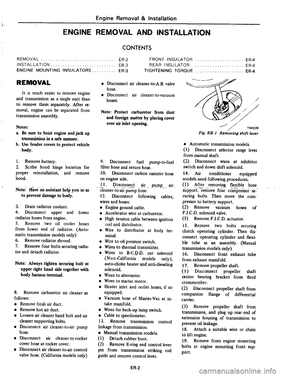
Fig
ER
l
Automatic
transmission
models
I
Disconnect
selector
range
lever
from
manual
shaft
2
Disconnect
wires
at
inhibitor
switch
and
down
shift
solenoid
14
Air
conditioner
equipped
models
need
following
procedures
1
After
removing
flexible
hose
support
remove
four
comi
ressor
se
curing
bolts
Then
move
the
com
pressor
to
battery
support
2
Remove
vacuum
hoses
of
F
LC
D
solenoid
valve
3
Remove
F
LC
D
actuator
15
Remove
two
bolts
securing
clutch
operating
cylinder
Then
dis
connect
operating
cylinder
and
flexi
ble
tube
as
an
assembly
Manual
transmission
models
only
16
Disconnect
front
exhaust
tube
from
exhaust
manifold
17
Remove
propeller
shaft
I
Disconnect
propeller
shaft
center
bearing
bracket
from
third
crossmember
2
Disconnect
propeller
shaft
from
companion
flange
of
differential
carrier
3
Remove
propeller
shaft
from
transmission
and
plug
up
rear
end
of
extension
housing
of
transmission
to
prevent
oil
leakage
18
Attach
a
suitable
wire
or
chain
to
lift
engine
19
Remove
front
engine
mounting
bolts
at
engine
mounting
front
sup
port
Page 377 of 537
The
620
series
vehicles
are
equip
ped
with
hydraulic
brakes
on
the
four
wheels
and
mechanical
hand
brakes
on
the
rear
wheels
The
front
brake
is
the
uni
servo
type
and
the
rear
the
duo
servo
with
the
built
in
hand
BRAKE
PEDAL
FRONT
BRAKE
REAR
BRAKE
BRAKE
PEDAL
Qi
f
l
II
t
Unit
mm
in
I
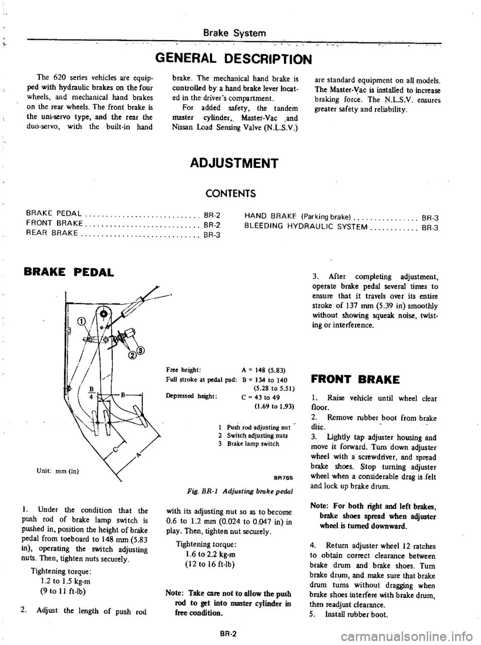
Under
the
condition
that
the
push
rod
of
brake
lamp
swi
tch
is
pushed
in
position
the
height
of
brake
pedal
from
toeboard
to
148
mm
5
83
in
operating
the
switch
adjusting
nuts
Then
tighten
nuts
securely
Tightening
torque
1
2
to
1
5
kg
m
9
to
I
I
ft
Ib
2
Adjust
the
length
of
push
rod
Brake
System
GENERAL
DESCRIPTION
brake
The
mechanical
hand
brake
is
controlled
by
a
hand
brake
lever
locat
ed
in
the
driver
s
compartment
For
added
safety
the
tandem
I
1lI3ter
cylinder
Master
Vac
and
Nissan
Load
Sensing
Valve
N
L
S
V
ADJUSTMENT
CONTENTS
are
standard
equipment
on
all
models
The
Master
Vac
is
installed
to
increase
braking
force
The
N
L
S
V
ensures
greater
safety
and
reliability
BR
2
BR
2
BR
3
HAND
BRAKE
Parking
brake
BLEEDING
HYDRAULIC
SYSTEM
BR
3
BR
3
Free
height
Full
stroke
at
pedal
pad
A
148
5
83
B
134
10
140
5
28
to
5
51
C
43
to
49
1
69
to
1
93
Depressed
height
1
Push
rod
adjusting
nut
2
Switch
adjusting
nuts
3
BraKe
lamp
switch
BA765
Fig
BR
l
Adjusting
brake
pedal
with
its
adjusting
nut
so
as
to
become
0
6
to
1
2
mOl
0
024
to
0
047
in
in
play
Then
tigh1en
nut
securely
Tightening
torque
1
6
to
2
2
kg
m
12
to
16
ft
lb
Note
Take
care
not
to
allow
the
push
rod
to
get
into
master
cylinder
in
free
condition
BR
2
3
After
completing
adjustment
operate
brake
pedal
several
times
to
ensure
that
it
travels
over
its
entire
stroke
of
137
mm
5
39
in
smoothly
without
showing
squeak
noise
twist
ing
or
interference
FRONT
BRAKE
1
Raise
vehicle
until
wheel
clear
floor
2
Remove
rubber
boot
from
brake
disc
3
Ughtly
tap
adjuster
housing
and
move
it
forward
Turn
down
adjuster
wheel
with
a
screwdriver
and
spread
brake
shoes
Stop
turning
adjuster
wheel
when
a
considerable
drag
is
Jelt
and
lock
up
brake
drum
Note
For
both
right
and
left
brakes
brake
shoes
spread
when
adjuster
wheel
is
turned
downward
4
Return
adjuster
wheel
12
ratches
to
obtain
correct
clearance
between
brake
drum
and
brake
shoes
Turn
brake
drum
and
make
sure
that
brake
drum
turns
without
dragging
when
brake
shoes
interfere
with
brake
drum
then
readjust
clearance
5
Install
rubber
boot
Page 385 of 537
Ibove
mentioned
st
is
available
when
op
the
FRONT
BRAKE
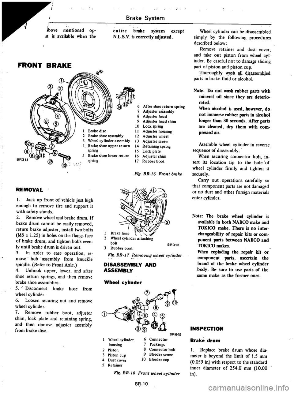
Brake
System
entire
brake
system
except
N
L
S
V
is
correctly
adjusted
After
shoe
return
spring
Adjuster
assembly
8
Adjuster
head
9
Adjuster
head
shim
10
Lock
spring
11
Adjuster
housing
12
Adjuster
wheel
13
Adjuster
screw
14
Retaining
spring
15
Lock
plate
16
Adjuster
shim
17
Rubber
boot
1
Brake
disc
2
Brake
shoe
assembly
3
Wheel
cylinder
assembly
4
Brake
shoe
upper
return
spring
5
Brake
shoe
lower
return
spring
REMOVAL
I
Jack
up
front
of
vehicle
just
high
enough
to
remove
tire
and
support
it
with
safety
stands
2
Remove
wheel
and
brake
drum
If
brake
drum
cannot
be
easily
removed
return
brake
adjuster
install
two
bolts
M8
x
1
25
in
holes
on
the
flange
face
of
brake
drum
and
tighten
bolts
even
ly
until
brake
drum
is
driven
out
3
In
order
to
ease
operation
re
move
hub
assembly
from
knucRle
spindle
Refer
to
Front
Axle
4
Unhook
upper
lower
and
after
shoe
return
springs
and
then
remove
brake
shoe
assemblies
S
Disconnect
brake
hose
from
wheel
cy
linder
6
Loosen
securing
nut
and
remove
wheel
cylinder
7
Remove
rubber
boot
adjuster
shim
lock
plate
and
retaining
spring
and
then
remove
adjuster
assembly
from
brake
disc
Fig
BR
I
6
Front
brake
1
Brake
hose
2
Wheel
cylinder
attaching
bolt
BA312
3
Rubber
boot
Fig
BR
17
Removing
wheel
cylinder
DISASSEMBLY
AND
ASSEMBLY
Wheel
cylinder
@
rr
l
@
t
a
Wheel
cy
linder
housing
2
Piston
3
Piston
cup
4
Dust
cover
5
Retainer
BR649
6
Connector
7
Packings
8
Connector
bolt
9
Bleeder
screw
10
Bleeder
cap
Wheel
cylinder
can
be
disassembled
simply
by
the
following
procedures
described
below
Remove
retainer
and
dust
cover
and
take
out
piston
from
wheel
cyl
inder
Be
careful
not
to
damage
sliding
part
of
piston
and
piston
cup
Thoroughly
wa
sh
u
disassembled
parts
in
brake
fluid
or
alcohol
Note
Do
not
wash
rubber
parts
with
mineral
oil
since
they
are
deterio
rated
When
alcohol
is
used
however
do
not
immerse
rubber
parts
in
alcohol
longer
than
30
seconds
After
parts
are
cleaned
dry
them
with
com
pressed
air
Assemble
wheel
cylinder
in
reverse
sequence
of
diassembly
When
securing
connector
bolt
in
sert
its
location
tip
to
the
hole
of
wheel
cylinder
firmly
and
tighten
it
securely
Carry
out
operations
carefully
so
that
component
parts
are
not
damaged
or
no
dust
and
other
foreign
materials
enter
cylinder
Note
The
brake
wheel
cylinder
is
available
in
both
NABCO
make
and
TOKICO
make
There
is
no
inter
changeability
of
repair
kits
or
com
ponent
parts
between
NABCO
and
TOKICO
makes
When
replacing
the
repair
kit
or
ent
parts
ascertain
the
brand
of
the
brake
wheel
cylinder
body
Be
sure
to
use
parts
of
the
same
make
as
the
former
ones
INSPECTION
Brake
drum
I
Replace
brake
drum
whose
dia
meter
is
beyond
the
limit
of
1
5
mm
0
OS9
in
with
respect
to
the
standard
inner
diameter
of
2S4
0
rom
10
00
SR
tO
Fig
BR
18
Front
wheel
cylinder
in
Page 387 of 537
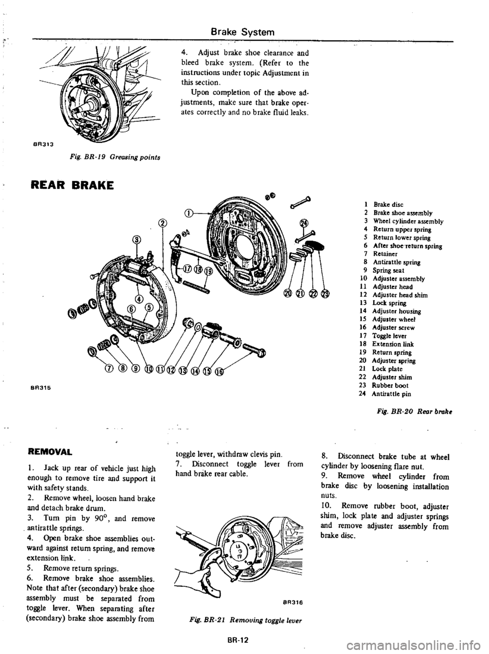
BA313
Fig
BR
19
Greasing
points
REAR
BRAKE
Brake
System
4
Adjust
brake
shoe
clearance
and
bleed
brake
system
Refer
to
the
instructions
under
topic
Adjustment
in
this
section
Upon
completion
of
the
above
ad
justments
make
sure
that
brake
oper
ates
correctly
and
no
brake
fluid
leaks
BA315
REMOVAL
I
Jack
up
rear
of
vehicle
just
high
enough
to
remove
lire
and
support
it
with
safety
stands
2
Remove
wheel
loosen
hand
brake
and
detach
brake
drum
3
Turn
pin
by
900
and
remove
antirattle
springs
4
Open
brake
shoe
assemblies
out
ward
against
return
spring
and
remove
extension
link
S
Remove
return
springs
6
Remove
brake
shoe
assemblies
Note
that
after
secondary
brake
shoe
assembly
must
be
separated
from
toggle
lever
When
separating
after
secondary
brake
shoe
assembly
from
toggle
lever
withdraw
clevis
pin
7
Disconnect
toggle
lever
from
hand
brake
rear
cable
BR316
Fig
BR
21
Remouing
toggle
leuer
BR
12
1
Brake
disc
2
Brake
shoe
assembly
3
Wheel
cylinder
assembly
4
Return
upper
spring
5
Return
lower
spring
6
After
shoe
return
spring
7
Retainer
8
Antirattle
spring
9
Spring
seat
10
Adjuster
assembly
11
Adjuster
head
12
Adjuster
head
shim
13
Lock
spring
14
Adjuster
housing
15
Adjuster
wheel
16
Adjuster
screW
17
Toggle
lever
18
Extension
link
19
Return
spring
20
Adjuster
spring
21
Lock
plate
22
Adjuster
shim
23
Rubber
boot
24
Antirattlc
pin
Fig
BR
20
Reor
brake
8
Disconnect
brake
tube
at
wheel
cylinder
by
loosening
flare
nut
9
Remove
wheel
cylinder
from
brake
disc
by
loosening
installation
nuts
10
Remove
rubber
boot
adjuster
shim
lock
plate
and
adjuster
springs
and
remove
adjuster
assembly
from
brake
disc