driver seat adjustment DATSUN PICK-UP 1977 Service Manual
[x] Cancel search | Manufacturer: DATSUN, Model Year: 1977, Model line: PICK-UP, Model: DATSUN PICK-UP 1977Pages: 537, PDF Size: 35.48 MB
Page 312 of 537

Automatic
Transmission
TROUBLE
DIAGNOSIS
AND
ADJUSTMENT
INSPECTION
AND
ADJUSTMENT
BEFORE
TRQUBLE
DIAGNOSIS
TESTING
INSTRUMENT
FOR
INSPECTION
CHECKING
OIL
LEVEL
INSPECTION
AND
REPAIR
OF
OIL
EAKAGE
CHECKING
ENGINE
IDLING
REVOLUTION
CHECKING
AND
ADJUSTING
KICKDOWN
SWITCH
AND
DqWNSHIFT
SOLENOID
N
J
J
CII
Q
t
L
8li
p
JYSTMs
T
OF
MANUAL
LINKAGE
CHECKING
AND
ADJUSTING
INHIBITOR
SWITCH
STALL
TEST
STALL
TEST
PROCEDURES
JUDGEMENT
Since
most
automatic
transmission
troubles
can
be
repaired
by
simple
adjustment
do
not
disassemble
im
mediately
Firstly
inspect
and
adjust
the
auto
matic
transmission
in
place
utilizing
the
Trouble
Shooting
Chart
If
the
trouble
can
not
be
solved
by
this
procedure
remove
and
disas
semble
the
automatic
transmission
It
is
advisable
to
check
overhaul
and
repair
each
part
in
the
order
listed
in
the
Trouble
Shooting
Chart
I
In
the
Trouble
Shooting
Chart
the
diagnosis
items
are
arranged
ac
cording
to
difficulty
from
easy
to
difficult
therefore
please
follow
these
items
The
transmission
should
not
be
removed
unless
necessary
2
Tests
and
adjustments
should
be
made
on
the
basis
of
standard
values
and
the
data
should
be
recorded
INSPECTION
AND
ADJUSTMENT
BEFORE
TROUBLE
DIAGNOSIS
TESTING
INSTRUMENT
FOR
INSPECTION
I
Engine
tachometer
2
Vacuum
gauge
ROAD
TEST
VEHICLE
SPEED
AT
GEAR
SHIFT
CHECKING
SPEED
CHANGING
CONDITION
CHECKING
ITEMS
DURING
SPEED
CHANGE
SHIFT
SCHEDULE
LINE
PRESSURE
TEST
LINE
PRESSURE
governor
feed
pressure
JUDGEMENT
IN
MEASURING
LINE
PRESSURE
At
49
TR6
uBLE
SHOOTINC
CHART
INSPECTING
ITEMS
TROUBLE
SHOOTING
CHART
FOR
3N71B
AUTOMATIC
TRANSMISSION
TROUBLE
SHOOTING
GUIDE
FOR
3N71B
AUTOMATIC
TRANSMISSION
CONTENTS
AT
4B
AT
48
AT
4B
AT
49
AT
49
AT
49
AT
49
AT
50
AT
50
AT
50
3
Oil
pressure
gauge
It
is
convenient
to
install
these
instruments
in
a
way
that
allows
meas
urements
to
be
made
from
the
driver
s
seat
CHECKING
OIL
LEVEL
In
checking
the
automatic
transmis
sion
the
o
illevel
and
the
condition
of
oil
around
the
oil
level
gauge
should
be
examined
This
is
an
easy
and
effective
trouble
shooting
procedure
since
some
changes
in
oil
condition
are
often
linked
with
developed
troubles
For
instance
Lack
of
oil
causes
faulty
operation
by
making
the
clutches
and
brakes
slip
resulting
in
severe
wear
This
is
because
the
oil
pump
sucks
air
causing
oil
foaming
thus
rapidly
deteriorating
the
oil
quality
and
pro
ducing
sludge
and
varnish
Excessive
oil
is
also
bad
because
of
oil
foaming
caused
by
the
gears
stirring
up
the
oil
During
high
speed
driving
excessive
oil
in
the
transmission
often
blows
out
from
the
breather
Measuring
011
level
To
check
the
fluid
level
start
the
engine
and
run
it
until
normal
operat
T
AO
AT
51
AT
51
AT
52
AT
52
AT
52
AT
52
AT
53
AT
3
AT
53
AT
53
AT
54
AT
57
ing
temperatures
o
temperature
SO
to
800C
122
to
l760F
Approxi
mately
ten
minute
of
operation
will
raise
the
temperature
to
this
range
and
engine
idling
conditions
are
stabi
lized
Then
apply
the
brakes
and
move
the
transmission
shift
lever
through
all
drive
positions
and
place
it
in
park
P
position
In
this
inspec
tion
the
car
must
be
placed
on
a
level
surface
The
amount
of
the
oil
varies
with
the
temperature
As
a
rule
the
oil
level
must
be
measured
after
its
temper
ture
becomes
sufficiently
high
1
Fill
the
oil
to
the
line
H
The
difference
of
capacities
between
both
H
and
L
is
approximately
0
4
liter
Ji
V
S
p
Y
Imp
pl
and
therefore
do
not
to
fill
beyond
the
line
H
2
When
topping
up
and
changing
oil
care
should
be
taken
to
prevent
mixing
the
oil
with
dust
and
water
InspectIng
011
condition
The
condition
of
oil
sticking
to
the
level
gauge
indicates
whether
to
over
haul
and
repair
the
transmission
or
look
for
the
faulty
part
If
the
oil
has
deteriorated
to
a
varnish
ike
quality
it
causes
the
con
trol
valve
to
stick
Blackened
oil
indi
cates
a
burned
clutch
brake
band
etc
Page 433 of 537

Body
Frame
Note
Vertical
adjustment
should
be
carried
out
after
hood
lock
male
and
female
adjustment
has
been
completed
3
To
correct
hood
lock
alignment
loosen
two
hood
lock
male
attaching
bolts
and
move
hood
lock
male
and
female
in
the
lateral
and
fore
and
aft
directions
as
required
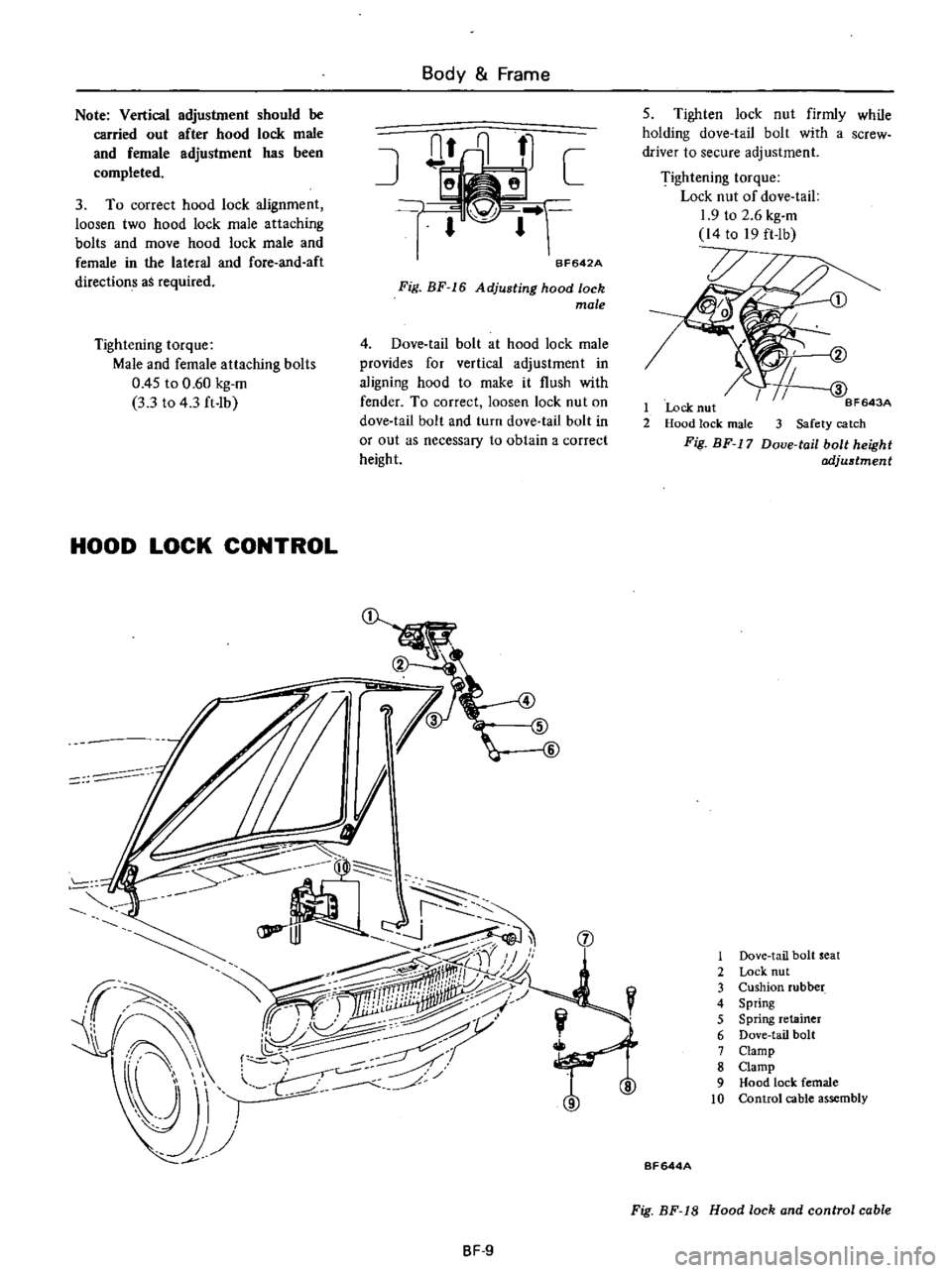
D
1r
r
BF642A
Fig
BF
16
Adjusting
hood
lock
male
Tightening
torque
Male
and
female
attaching
bolts
0
45
to
0
60
kg
m
3
3
to
4
3
ft
Ib
4
Dove
tail
bolt
at
hood
lock
male
provides
for
vertical
adjustment
in
aligning
hood
to
make
it
flush
with
fender
To
correct
loosen
lock
nut
on
dove
tail
bolt
and
turn
dove
tail
bolt
in
or
out
as
necessary
to
obtain
a
correct
height
HOOD
LOCK
CONTROL
JI
I
i
I
r
lPP
J
jJ
J
Sr
aj
I
I
I
J
f
ifry
ff
I
ii1iiilliii
j
iW
r
U
I
j
Y
f
7
j
1
JJ
J
8F
9
5
Tighten
lock
nut
firmly
while
holding
dove
tail
bolt
with
a
screw
driver
to
secure
adjustment
Tightening
torque
Lock
nut
of
dove
tail
1
9
to
2
6
kg
m
14
to
19
ft
lb
BF643A
1
Lock
nut
2
Hood
lock
male
3
Safety
catch
Fig
BF
17
Doue
tail
bolt
height
adjustment
1
Dove
tail
bolt
seat
2
Lock
nut
3
Cushion
rubber
4
Spring
5
Spring
retainer
6
Dove
tail
bolt
7
Clamp
8
Clamp
9
Hood
lock
female
10
Control
cable
assembly
BF644A
Fig
BF
18
Hood
lock
and
control
cable