jacking DATSUN PICK-UP 1977 Service Manual
[x] Cancel search | Manufacturer: DATSUN, Model Year: 1977, Model line: PICK-UP, Model: DATSUN PICK-UP 1977Pages: 537, PDF Size: 35.48 MB
Page 9 of 537

Fig
GI
9
Manual
trammiuion
number
location
Automatic
transmission
number
The
transmission
serial
number
is
attached
to
the
right
hand
side
of
transmission
case
Numbering
system
X
XXXXX
I
Serial
number
monthly
Month
of
manufacture
I
2
9
X
Y
Z
last
figure
of
year
of
manufacture
AT344
Fig
01
10
Automatic
trammi
sion
number
location
LIFTING
POINTS
AND
TOWING
LIFTING
POINTS
Screw
jack
Before
using
the
jack
proceed
a
follows
Generallnforml
ition
Apply
parking
brake
firmly
and
block
rear
wheels
if
the
front
of
the
vehicle
is
to
be
raised
Notes
a
Never
get
under
the
vehicle
while
it
is
supported
only
by
the
jack
Always
use
safety
stands
to
support
frame
or
rear
axle
case
when
you
have
to
get
beneath
the
vehicle
b
In
no
event
should
the
jack
be
applied
to
any
points
except
the
following
specified
portions
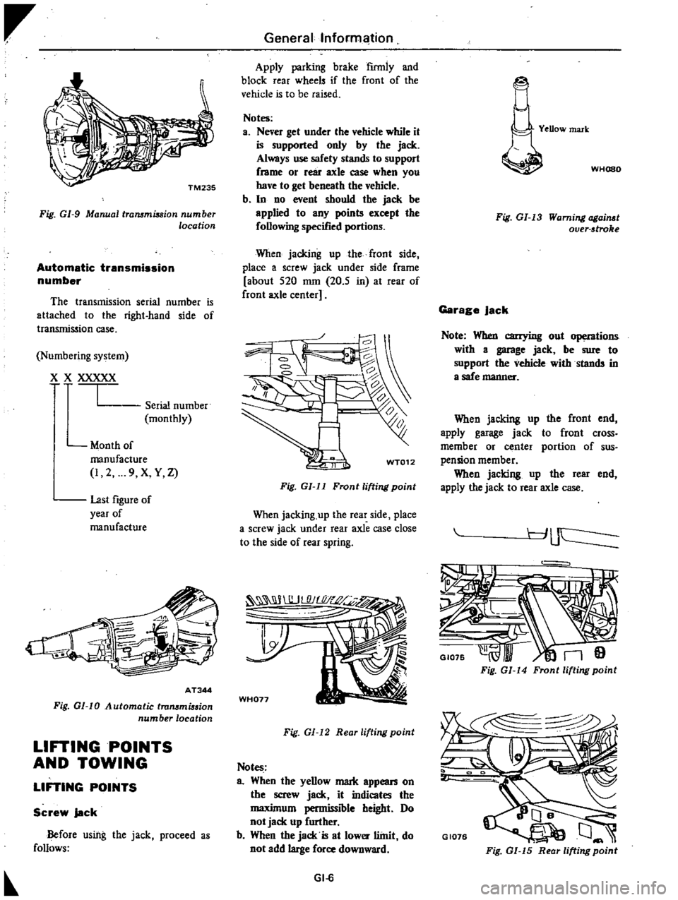
When
jacking
up
the
front
side
place
a
screw
jack
under
side
frame
about
520
nun
20
5
in
at
rear
of
front
axle
center
WT012
Fig
GI
ll
Front
lifting
point
When
jacking
up
the
rear
side
place
a
screw
jack
under
rear
axle
case
close
to
the
side
of
rear
spring
WH077
Fig
GI
12
Reor
lifting
point
Notes
a
When
the
yellow
mark
appean
on
the
screw
jack
it
indicates
the
maximum
permissible
height
Do
not
jack
up
further
b
When
the
jack
is
at
lower
llinit
do
not
add
large
force
downward
GI
6
YeDow
mark
WHOSO
Fig
GI
13
Warning
ogai
t
over
stroke
Garage
Jack
Note
When
carrying
out
operntions
with
a
garage
jack
be
sure
to
support
the
vehicle
withstands
in
a
safe
manner
When
jacking
up
the
front
end
apply
garage
jack
to
front
cross
member
or
center
portion
of
sus
pension
member
When
jacking
up
the
rear
end
apply
the
jack
to
rear
axle
case
r
J
uc
I
GI075
n9
Fig
GI
14
Front
lifting
point
GI076
Fig
GI
15
Rear
lifting
point
Page 403 of 537

Center
This
wear
is
caused
by
overinflation
of
the
tire
The
inflation
pressure
must
be
kept
at
the
specified
value
Shoulder
The
wear
may
be
caused
by
under
inflation
incorrect
wheel
camber
or
continuous
high
speed
driving
on
curves
In
general
the
former
two
causes
are
common
Underinflation
wear
occurs
on
both
sides
of
treads
d
I
Ii
Toe
in
or
toe
out
wear
nf
I
Underinnation
wear
TIRE
ROTATION
Tires
wear
unevenly
and
become
unbalanced
according
to
running
dis
tance
Uneven
tire
wear
often
results
in
tire
noise
which
is
attributed
to
rear
axle
gears
bearing
etc
Meanwhile
the
front
tires
tend
to
wear
unevenly
because
of
improperly
aligned
front
wheel
Accordingly
to
equalize
tire
wear
it
is
necessary
to
rotate
tires
peri
odically
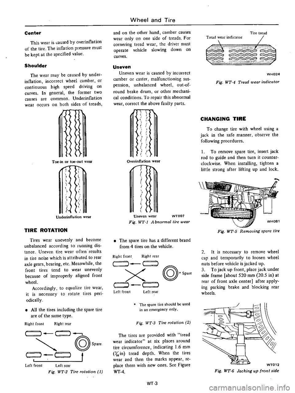
All
the
tires
including
the
spare
tire
are
of
the
same
type
Right
front
Right
rear
14
1
I
@
Spare
t
t
1
1
Left
front
Left
rear
Fig
WT
2
Tire
rotation
1
Wheel
and
Tire
and
on
the
other
hand
camber
causes
wear
only
on
one
side
of
treads
For
cornering
tread
wear
the
driver
must
operate
vehicle
slowing
down
on
curves
Uneven
Uneven
wear
is
caused
by
incorrect
camber
or
caster
malfunctioning
sus
pension
unbalanced
wheel
out
of
round
brake
drum
or
other
mechani
cal
conditions
To
repair
this
abnormal
wear
correct
the
above
faulty
parts
J
I
II
i
11
I
1
Overinllation
wear
1
I
I
t
Uneven
wear
WT007
Fig
WT
1
A
bnormal
tire
wear
The
spare
lire
has
a
different
brand
from
4
tires
on
the
vehicle
Right
front
Right
rear
I
@
Spare
x
J
r
Left
front
Left
rear
The
pare
tire
should
be
used
in
an
emergency
only
Fig
WT
3
Tire
rotation
2
The
tires
are
provided
with
tread
wear
indicator
at
six
places
around
tire
circumference
indicating
1
6
mm
J
in
tread
depth
When
the
tires
wear
and
then
the
marks
appear
re
place
them
with
new
ones
See
Figure
WT
4
WT3
Tire
tread
0E
I
Tread
wear
indicator
c
WH024
Fig
WT
4
Tread
wear
indicator
CHANGING
TIRE
To
change
tire
with
wheel
using
a
jack
in
the
safe
manner
observe
the
following
procedures
1
To
remove
spare
tire
insert
jack
rod
to
guide
and
then
turn
it
counter
clockwise
When
installing
lighten
a
little
strong
after
lifting
up
and
lock
Fig
WT
5
Removing
spare
tire
2
It
is
necessary
to
remove
wheel
cap
and
temporarily
to
loosen
wheel
nuts
before
vehicle
is
jacked
up
3
To
jack
up
front
place
jack
under
side
frame
about
S20
mOl
20
5
in
at
rear
of
front
axle
center
after
apply
ing
parking
brake
and
blocking
rear
wheels
g
1
WT012
Fig
WT
6
Jacking
up
front
side
Page 404 of 537

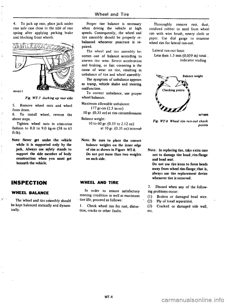
4
To
jack
up
rear
place
jack
under
rear
axle
case
close
to
the
side
of
rear
spring
after
applying
parking
brake
and
blocking
front
wheels
WH077
Fig
WT
7
Jacking
up
rear
side
S
Remove
wheel
nuts
and
wheel
from
drum
6
To
install
wheel
reverse
the
above
steps
Tighten
wheel
nuts
in
criss
cross
fashion
to
8
0
to
9
0
kg
m
S8
to
6S
ft
Ib
Note
Nerer
get
under
the
vehicle
while
it
is
supported
only
by
the
jack
Always
use
S8
fety
stands
to
support
the
side
member
of
body
construction
when
you
must
get
beneath
the
vehicle
INSPECTION
WHEEL
BALANCE
The
wheel
arid
tire
asSembly
should
be
kept
balanced
statically
and
dynam
ically
Wheel
and
Tire
Proper
tire
balance
is
necessary
when
driving
the
vehicle
at
high
speeds
Consequently
the
wheel
and
tire
assembly
should
be
properly
re
balanced
whenever
puncture
is
re
paired
The
wheel
and
tire
assembly
be
comes
out
of
ba1ance
according
to
uneven
tire
wear
Severe
acceleration
and
braking
or
fast
cornering
is
the
cause
of
wear
on
tire
resulting
in
unbalance
of
tire
and
wheel
assembly
The
symptom
of
unbalance
appears
as
tramp
vehicle
shake
and
steering
malfunction
To
correct
unbalance
use
proper
wheel
balancer
Maximum
allowable
unbalance
177
gr
cm
2
5
in
oz
10
gr
O
3S
oz
at
rim
circumferences
Balance
weight
10
to
60
gr
O
3S
to
2
12
oz
at
10
gr
0
3S
oz
intervat
Note
Be
sure
to
place
the
correct
balance
weights
on
the
inner
edge
of
rim
as
shown
in
Figure
WT
S
00
not
put
more
than
two
weights
on
each
side
WHEEL
AND
TIRE
In
order
to
ensure
satisfactory
steering
condition
as
well
as
maximum
tire
life
proceed
as
follows
Check
wheel
rim
for
rust
distor
tion
cracks
or
other
faults
WT
4
Thoroughly
remove
rust
dust
oxidized
rubber
or
sand
from
wheel
rim
with
wire
brush
emery
cloth
or
paper
Use
dial
gauge
to
examine
wheel
rim
for
lateral
run
out
Lateral
run
Qut
limit
Less
tltan
1
5
mOl
0
059
il
total
indicator
reading
WTOO5
Fig
WT
B
Whetl
rim
run
out
check
points
Note
In
replacing
tire
t
e
extra
care
not
to
damage
tire
bead
rim
flange
and
bead
seat
Do
not
use
tire
irons
to
force
beads
away
from
wheel
rim
flange
that
is
always
use
tire
replacement
device
whenever
tire
is
removed
2
Discard
when
any
of
the
follow
ing
problems
occur
1
Broken
or
damaged
bead
wire
2
Ply
o
treairsepanitiori
3
Cracked
or
damaged
side
wall
etc