open gas tank DATSUN PICK-UP 1977 Service Manual
[x] Cancel search | Manufacturer: DATSUN, Model Year: 1977, Model line: PICK-UP, Model: DATSUN PICK-UP 1977Pages: 537, PDF Size: 35.48 MB
Page 94 of 537

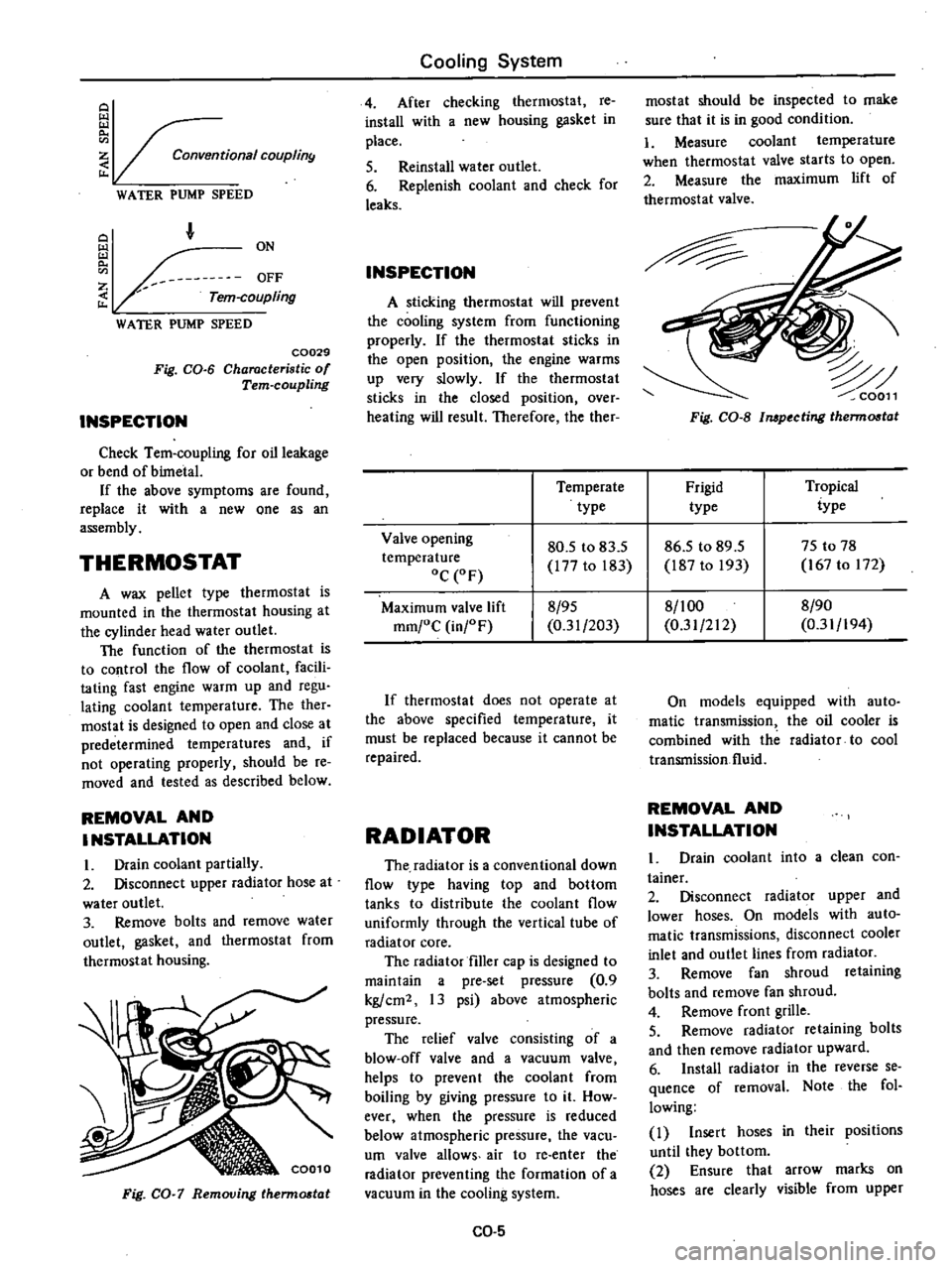
Conventional
COUplin9
WATER
PUMP
SPEED
F
Z
Tern
coupling
WATER
PUMP
SPEED
C0029
Fig
CO
6
Characteristic
of
Tern
coupling
INSPECTION
Check
Tem
coupling
for
oil
leakage
or
bend
of
bimetal
If
the
above
symptoms
are
found
replace
it
with
a
new
one
as
an
assembly
THERMOSTAT
A
wax
pellet
type
thermostat
is
mounted
in
the
thermostat
housing
at
the
cylinder
head
water
outlet
The
function
of
the
thermostat
is
to
control
the
flow
of
coolant
facili
tating
fast
engine
warm
up
and
regu
lating
coolant
temperature
The
ther
mostat
is
designed
to
open
and
close
at
predetermined
temperatures
and
if
not
operating
properly
should
be
re
moved
and
tested
as
described
below
REMOVAL
AND
INSTALLATION
I
Drain
coolant
partially
2
Disconnect
upper
radiator
hose
at
water
outlet
3
Remove
bolts
and
remove
water
outlet
gasket
and
thermostat
from
thermostat
housing
Fig
CO
7
Removing
therm06t
t
Cooling
System
4
After
checking
thermostat
re
install
with
a
new
housing
gasket
in
place
5
Reinstall
water
outlet
6
Replenish
coolant
and
check
for
leaks
INSPECTION
A
sticking
thermostat
will
prevent
the
cooling
system
from
functioning
properly
If
the
thermostat
sticks
in
the
open
position
the
engine
warms
up
very
slowly
If
the
thermostat
sticks
in
the
closed
position
over
heating
will
result
Therefore
the
ther
mostat
should
be
inspected
to
make
sure
that
it
is
in
good
condition
1
Measure
coolant
temperature
when
thermostat
valve
starts
to
open
2
Measure
the
maximum
lift
of
thermostat
valve
Fig
CO
S
Impecting
therm06t
t
Temperate
Frigid
Tropical
type
type
iype
Valve
opening
80
5
to
83
5
86
5
to
89
5
75
to
78
temperature
177
to
183
187
to
193
167
to
172
oC
OF
Maximum
valve
lift
8
95
8
1
00
8
90
mm
oC
in
F
0
31
203
0
31
212
0
31
194
If
thermostat
does
not
operate
at
the
above
specified
temperature
it
must
be
replaced
because
it
cannot
be
repaired
RADIATOR
The
radiator
is
a
conventional
down
flow
type
having
top
and
bottom
tanks
to
distribute
the
coolant
flow
uniformly
through
the
vertical
tube
of
radiator
core
The
radiator
filler
cap
is
designed
to
maintain
a
pre
set
pressure
0
9
kg
cm2
13
psi
above
atmospheric
pressure
The
relief
valve
consisting
of
a
blow
off
valve
and
a
vacuum
valve
helps
to
prevent
the
coolant
from
boiling
by
giving
pressure
to
it
How
ever
when
the
pressure
is
reduced
below
atmospheric
pressure
the
vacu
um
valve
allows
air
to
re
enter
the
radiator
preventing
the
formation
of
a
vacuum
in
the
cooling
system
CO
5
On
models
equipped
with
auto
matic
transmission
the
oil
cooler
is
combined
with
the
radiator
to
cool
transmission
fluid
REMOVAL
AND
INSTALLATION
Drain
coolant
into
a
clean
con
tainer
2
Disconnect
radiator
upper
and
lower
hoses
On
models
with
auto
matic
transmissions
disconnect
cooler
inlet
and
outlet
lines
from
radiator
3
Remove
fan
shroud
retaining
bolts
and
remove
fan
shroud
4
Remove
front
grille
5
Remove
radiator
retaining
bolts
and
then
remove
radiator
upward
6
Install
radiator
in
the
reverse
se
quence
of
removal
Note
the
fol
lowing
I
Insert
hoses
in
their
positions
until
they
bottom
2
Ensure
that
arrow
marks
on
hoses
are
clearly
visible
from
upper
Page 105 of 537

DESCRIPTION
FUEL
PUMP
TESTING
STATIC
PRESSURE
TEST
CAPACITY
TEST
DESCRIPTION
The
fuel
pump
transfers
fuel
from
the
tank
to
the
carburetor
in
sufficient
quantity
to
meet
the
engine
require
ments
at
any
speed
or
load
The
fuel
pump
is
a
pulsating
type
designed
for
easy
maintenance
It
con
sists
of
a
body
a
rocker
arm
assembly
a
fuel
diaphragm
a
fuel
diaphragm
spring
seal
inlet
and
outlet
valves
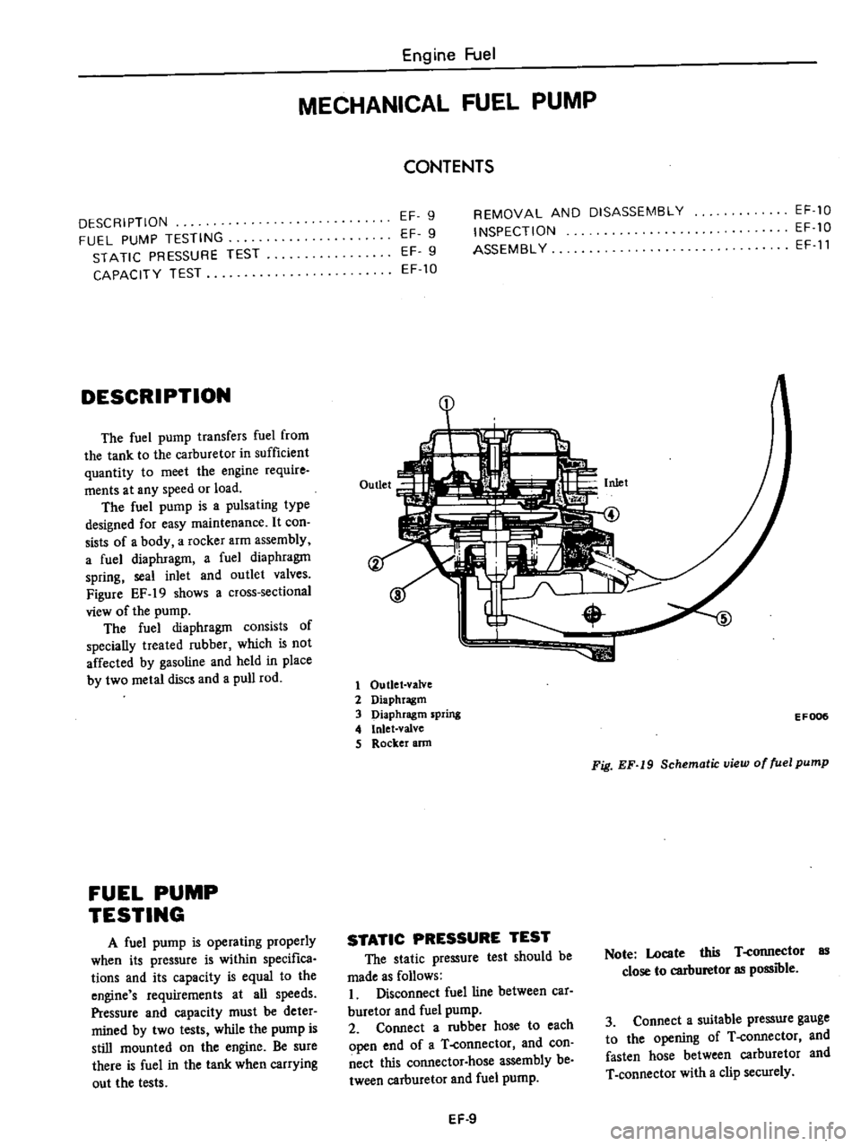
Figure
EF
19
shows
a
cross
sectional
view
of
the
pump
The
fuel
diaphragm
consists
of
specially
treated
rubber
which
is
not
affected
by
gasoline
and
held
in
place
by
two
metal
discs
and
a
pull
rod
FUEL
PUMP
TESTING
A
fuel
pump
is
operating
properly
when
its
pressure
is
within
specifica
tions
and
its
capacity
is
equal
to
the
engine
s
requirements
at
all
speeds
Pressure
and
capacity
must
be
deter
mined
by
two
tests
while
the
pump
is
still
mounted
on
the
engine
Be
sure
there
is
fuel
in
the
tank
when
carrying
out
the
tests
Engine
Fuel
MECHANICAL
FUEL
PUMP
CONTENTS
EF
9
EF
9
EF
9
EF
10
REMOVAL
AND
DISASSEMBLY
INSPECTION
ASSEMBL
Y
EF
10
EF
10
EF
11
1
1
Outlet
valve
2
Diaphragm
3
Diaphragm
spring
4
Inlet
valve
S
Rocker
ann
EF006
Fig
EF
19
Schematic
view
of
fuel
pump
STATIC
PRESSURE
TEST
The
static
pressure
test
should
be
made
as
follows
I
Disconnect
fuel
line
between
car
buretor
and
fuel
pump
2
Connect
a
rubber
hose
to
each
open
end
of
a
T
connector
and
con
nect
this
connector
hose
assembly
be
tween
carburetor
and
fuel
pump
Note
Locate
this
T
connector
as
close
to
carburetor
as
possible
3
Connect
a
suitable
pressure
gauge
to
the
opening
of
T
connector
and
fasten
hose
between
carburetor
and
T
connector
with
a
clip
securely
EF
9
Page 108 of 537

854
co
in
in
one
minute
or
less
If
no
gasoline
or
only
a
little
flows
from
open
end
of
pipe
with
pump
operated
or
if
pump
does
not
work
perform
the
following
diagnosis
Notes
3
Do
not
connect
battery
in
reverse
polarity
which
if
left
for
a
long
time
would
damage
transitor
circuit
and
disable
pump
Engine
Fuel
b
Do
not
let
fall
pump
as
it
may
damage
electronic
components
c
Do
not
apply
overvoitage
max
l
8Y
Overvoltage
starting
by
quick
charge
or
tage
running
would
deteriorate
or
damage
elec
tronic
components
Fuel
pressure
maximum
0
32
kg
cm
4
6
psi
REMOVAL
AND
INSTALLATION
Flom
fuel
tank
Electric
fuel
pump
is
installed
on
bracket
with
two
bolts
This
bracket
is
located
on
R
H
side
member
adjacent
to
fuel
tank
I
Remove
inlet
hose
from
fuel
pump
Also
remove
outlet
hose
run
ning
to
engine
Receive
fuel
remaining
in
fuel
hose
in
a
suitable
container
2
Disconnect
harness
at
connector
3
Remove
bolts
securing
fuel
pump
to
bracket
and
detach
fuel
pump
4
Installation
is
the
reverse
order
of
removal
9
@
1
Cover
2
Magnet
3
Cover
gasket
4
Filter
5
Gasket
6
Spring
retainer
7
Washer
8
O
ring
9
Inlet
valve
10
Retutn
PIing
11
Plunger
12
Plunger
cylinder
13
Body
To
carburetor
1
Elecuic
fuel
pump
2
Mounting
bracket
3
Fuel
mter
EF72D
Fig
EF
23
Electric
fuel
pump
DISASSEMBLY
Do
not
disassemble
unless
pump
is
faulty
I
Remove
cover
with
wrench
and
take
out
cover
gasket
magnet
and
filter
from
pump
body
2
When
removing
plunger
take
out
spring
retainer
from
plunger
tube
3
Then
take
out
washer
O
ring
inlet
valve
return
spring
and
plunger
from
tube
Note
Do
not
disassemble
electronic
components
If
n
replace
with
new
ones
6
EF721
Fig
EF
24
Exploded
view
of
electric
fuel
pump
EF
12
ASSEMBLY
I
Before
assembly
clean
all
parts
with
gasoline
and
compressed
air
com
pletely
Notes
a
If
gask
t
an
d
fdterare
faulty
r
place
b
Clean
magnet
and
cover
for
fault
c
Take
care
not
to
defonn
thin
tube
d
Assemble
plunger
return
spring
inlet
valve
O
ring
washer
and
set
spring
retainer
in
that
order
e
Assemble
filter
gasket
and
cover
with
f
Tighten
cover
with
wrench
to
the
stopper
If
component
parts
are
dirty
after
disassembly
clean
as
follows
Wash
fIlter
and
strainer
with
clean
gasoline
and
blow
with
compressed
air
When
cleaning
parts
check
fllter
for
fault
If
faulty
replace
Wash
plunger
plunger
cylinder
and
inlet
valve
with
clean
gasoline
and
blow
dust
off
with
compressed
air
2
Check
c
v
m
lI
parts
for
wear
or
damage
If
they
are
found
faulty
replace
them
3
Insert
plunger
assembly
into
plunger
cylinder
of
body
and
apply
electric
current
to
it
Move
the
assembly
up
and
down
If
the
assembly
does
not
move
it
shows
that
the
electric
uuit
is
faulty
and
it
must
be
replaced