tires DATSUN PICK-UP 1977 Service Manual
[x] Cancel search | Manufacturer: DATSUN, Model Year: 1977, Model line: PICK-UP, Model: DATSUN PICK-UP 1977Pages: 537, PDF Size: 35.48 MB
Page 342 of 537
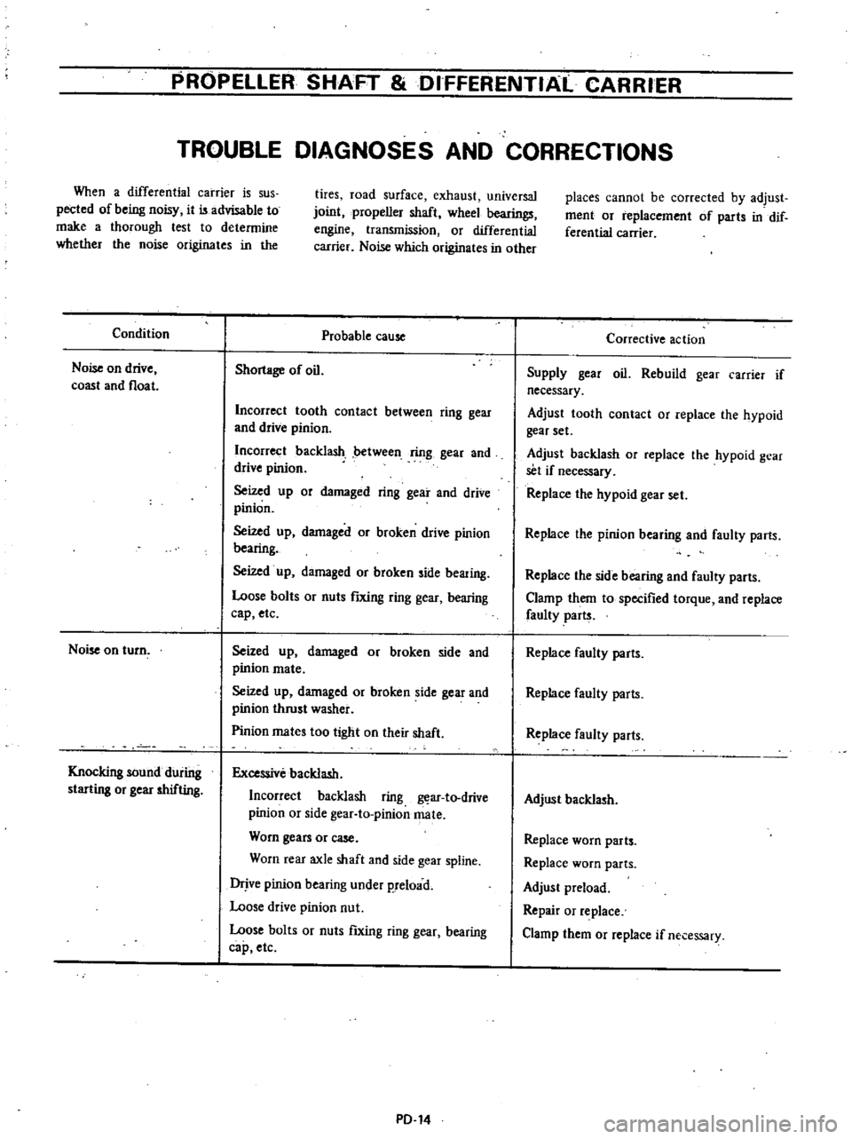
PROPELLER
SHAFT
DIFFERENTIAl
CARRIER
TROUBLE
DIAGNOSES
AND
CORRECTIONS
When
a
differential
carrier
is
sus
pected
of
being
noisy
it
is
advisable
to
make
a
thorough
lest
to
determine
whether
the
noise
originates
in
the
Condition
Noise
on
drive
coast
and
float
Noise
on
turn
Knocking
sound
during
starting
or
gear
shifting
tires
road
surface
exhaust
universal
joint
propeller
shaft
wheel
bearings
engine
transmission
or
differential
carrier
Noise
which
originates
in
other
Probable
cause
Shortage
of
oil
Incorrect
tooth
contact
between
ring
gear
and
drive
pinion
Incorrect
backlash
between
ring
gear
and
drive
pinion
Seized
up
or
damaged
ring
gear
and
drive
pinion
Seized
up
damaged
or
broken
drive
pinion
bearing
Seized
up
damaged
or
broken
side
bearing
Loose
bolts
or
nuts
fIXing
ring
gear
bearing
cap
etc
Seized
up
damaged
or
broken
side
and
pinion
mate
Seized
up
damaged
or
broken
side
gear
and
pinion
thrust
washer
Pinion
mates
too
tight
on
their
shaft
Excessive
backlash
Incorrect
backlash
ring
ar
to
drive
pinion
or
side
gear
to
pinionmate
Worn
gears
or
case
Worn
rear
axle
shaft
and
side
gear
spline
Drjve
pinion
bearing
under
p
reload
Loose
drive
pinion
nut
Loose
bolts
or
nuts
ftxing
ring
gear
bearing
cap
etc
PD
14
places
cannot
be
corrected
by
adjust
ment
or
replacement
of
parts
in
dif
ferential
carrier
Corrective
action
Supply
gear
oil
Rebuild
gear
carrier
if
necessary
Adjust
tooth
contact
or
replace
the
hypoid
gear
set
Adjust
backlash
or
replace
the
hypoid
gear
set
if
necessary
Replace
the
hypoid
gear
set
Replace
the
pinion
bearing
and
faulty
parts
Replace
the
side
bearing
and
faulty
parts
Clamp
them
to
specified
torque
and
replace
faulty
parts
Replace
faulty
parts
Replace
faulty
parts
Replace
faulty
parts
Adjust
backlash
Replace
worn
parts
Replace
worn
parts
Adjust
preload
Repair
or
replace
Clamp
them
or
replace
if
necessary
Page 361 of 537
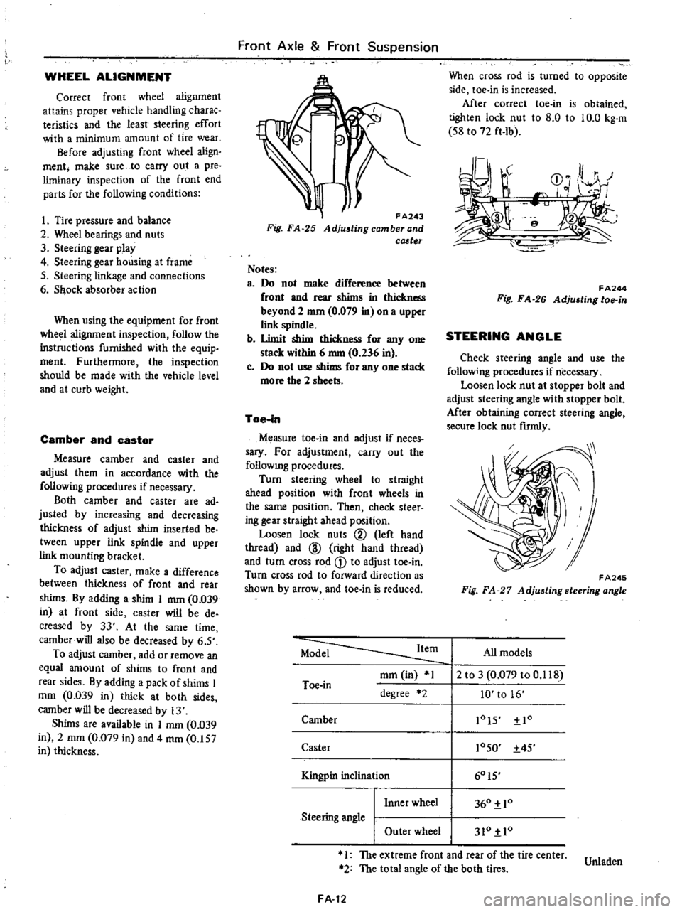
WHEEL
ALIGNMENT
Correct
front
wheel
alignment
attains
proper
vehicle
handling
charac
teristics
and
the
least
steering
effort
with
a
minimum
amount
of
tire
wear
Before
adjusting
front
wheel
align
ment
make
sure
to
carry
out
a
pre
liminary
inspection
of
the
front
end
parts
for
the
following
conditions
1
Tire
pressure
and
balance
2
Wheel
bearings
and
nuts
3
Steering
gear
play
4
Steering
gear
housing
at
frame
S
Steering
linkage
and
connections
6
Shock
absorber
action
When
using
the
equipment
for
front
wheel
alignment
inspection
follow
the
inst
c
tions
furnished
with
the
equip
ment
Furthennore
the
inspection
should
be
made
with
the
vehicle
level
and
at
curb
weight
Camber
and
caster
Measure
camber
and
caster
and
adjust
them
in
accordance
with
the
following
procedures
if
necessary
Both
camber
and
caster
are
ad
justed
by
increasing
and
decreasing
thickness
of
adjust
shim
inserted
be
tween
upper
link
spindle
and
upper
link
mounting
bracket
To
adjust
caster
make
a
difference
between
thickness
of
front
and
rear
shims
By
adding
a
shim
I
mm
0
039
in
at
front
side
caster
will
be
de
creased
by
33
At
the
same
time
camber
will
also
be
decreased
by
6
S
To
adjust
camber
add
or
remove
an
equal
amount
of
shims
to
front
and
rear
sides
By
adding
a
pack
of
shims
I
mOl
0
039
in
thick
at
both
sides
camber
will
be
decreased
by
13
Shims
are
available
in
I
mm
0
039
in
2
mOl
0
079
in
and
4
mOl
0
157
in
thickness
Front
Axle
Front
Suspension
FA243
Fig
FA
25
Adjustingcamberand
cCJ
ter
Notes
a
Do
not
make
difference
between
front
and
rear
shims
in
thickness
beyond
2
mm
0
079
in
on
a
upper
link
spindle
b
Umit
shim
thickness
for
anyone
stack
within
6
nun
0
236
in
c
Do
not
use
shims
for
anyone
stack
more
the
2
sheets
Toe
in
Measure
toe
in
and
adjust
if
neces
sary
For
adjustment
carry
out
the
follOWIng
procedures
Turn
steering
wheel
to
straight
ahead
position
with
front
wheels
in
the
same
position
Then
check
steer
ing
gear
straight
ahead
position
Loosen
lock
nuts
@
left
hand
thread
and
ID
right
hand
thread
and
turn
cross
rod
CD
to
adjust
toe
in
Turn
cross
rod
to
forward
direction
as
shown
by
arrow
and
toe
in
is
reduced
When
cross
rod
is
turned
to
opposite
side
toe
in
is
increased
After
correct
toe
in
is
obtained
tighten
lock
nut
to
8
0
to
10
0
kg
m
S8
to
72
ft
Ib
r
J
r
CD
0
HI
r
I
e
f
FA244
Fig
FA
26
Adju6ting
toe
in
STEERING
ANGLE
Check
steering
angle
and
use
the
follow
ng
procedures
if
necessary
Loosen
lock
nut
at
stopper
bolt
and
adjust
steering
angle
with
stopper
bolt
Mter
obtaining
correct
steering
angle
secure
lock
nut
firmly
FA245
Fig
FA
27
Adjusting
steering
angle
Model
Item
All
models
mOl
in
1
2
to
3
0
079
to
0
118
Toe
in
degree
2
10
to
16
Camber
lOIS
Io
Caster
10SO
4S
I
60IS
Kingpin
inc
inal10n
I
Inner
wheel
360
10
Steering
angle
I
Outer
wheel
310
10
1
The
extreme
front
and
rear
of
the
tire
center
Unladen
2
The
total
angle
of
the
both
tires
FA
12
Page 363 of 537
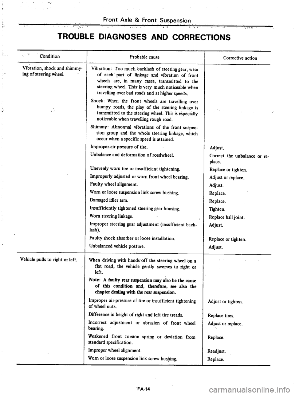
Front
Axle
Front
Suspension
TROUBLE
DIAGNOSES
AND
CORRECTIONS
Condition
Vibration
shock
and
shimmy
ing
of
steering
wheeL
Vehicle
pulls
to
right
or
left
Probable
cause
Vibration
Too
much
backlash
of
steering
gear
wear
of
each
part
of
linkage
and
vibration
of
front
wheels
are
in
many
cases
transmitted
to
the
steering
wheel
This
is
Very
much
noticeable
when
traveJling
over
bad
roads
and
at
higher
speeds
Shock
When
the
front
wheels
are
travelling
over
bumpy
roads
the
play
of
the
steering
linkage
is
transmitted
to
the
steering
wheel
This
is
especially
noticeable
when
travelling
rough
road
Shimmy
Abnormal
vibrations
of
the
front
suspen
sion
group
and
the
whole
steering
linkage
which
occur
when
a
specific
speed
is
attained
Improper
air
pressure
of
tire
Unbalance
and
deformation
of
roadwheel
Unevenly
worn
tire
or
insufficient
tightening
Improperly
adjusted
or
worn
front
wheel
bearing
Faulty
wheel
alignment
Worn
or
loose
suspension
link
screw
bushing
Damaged
idler
arm
Insufficiently
tightened
steering
gear
housing
Worn
steering
linkage
Improper
steering
gear
adjustment
insufficient
back
lash
Faulty
shock
absorber
or
loose
installation
Unbalanced
vehicle
posture
When
driving
with
hands
off
the
steering
wheel
on
a
fiat
road
the
vehicle
gently
swerves
to
right
or
left
Note
A
faulty
rear
suspension
may
also
be
the
cause
of
this
condition
and
therefore
see
also
the
chapter
dealing
with
the
rear
suspension
Improper
air
pressure
of
tire
or
insufficient
tightening
of
wheel
nu
ts
Difference
in
height
of
right
and
left
tire
treads
Incorrect
adjustment
or
abrasion
of
front
wheel
bearing
Weakened
front
torsion
spring
or
deviation
from
standard
specification
Improper
wheel
alignment
Worn
or
loose
suspension
link
screw
bushing
FA
14
Corrective
action
Adjust
Correct
the
unbalance
or
re
place
Replace
or
tighten
Adjust
or
replace
Adjust
Replace
Replace
TIghten
Replace
ball
joint
Adjust
Replace
or
tighten
Adjust
Adjust
or
tighten
Replace
tires
Adjust
or
replace
Replace
Readjust
Replace
Page 374 of 537
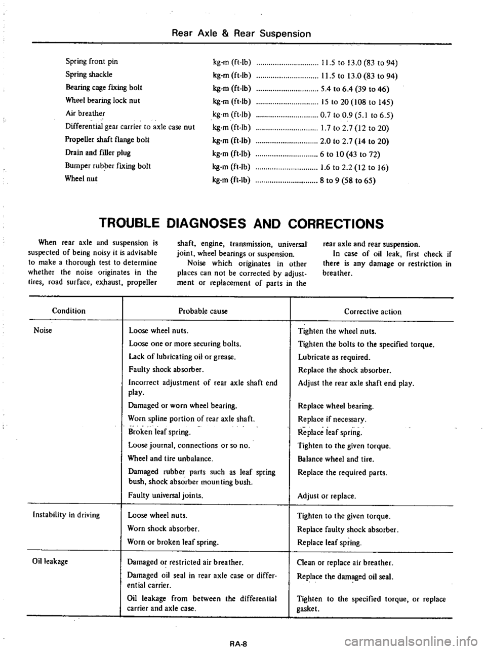
Rear
Axle
Rear
Suspension
Spring
front
pin
Spring
shackle
Bearing
cage
fIXing
bolt
Wheel
bearing
lock
nut
Air
breather
Differential
gear
carrier
to
axle
case
nut
Propeller
shaft
flange
bolt
Drain
and
filler
plug
Bumper
rubber
fixing
bolt
Wheel
nut
kg
m
ft
lb
kg
m
ft
Ib
kg
en
ft
lb
kg
m
ft
Ib
kg
m
ft
Ib
kg
m
ft
Ib
kg
en
ft
Ib
kg
m
ft
Ib
kg
m
ft
Ib
kg
m
ft
lb
11
5
to
13
0
83
to
94
11
5
to
13
0
83
to
94
S
4
to
6
4
39
to
46
IS
to
20
108
to
l4S
0
7
to
0
9
S
I
to
6
S
17
to
2
7
12
to
20
2
0
to
2
7
14
to
20
6
to
10
43
to
72
1
6
to
2
2
12
to
16
8
to
9
S8
to
6S
TROUBLE
DIAGNOSES
AND
CORRECTIONS
When
rear
axle
and
suspension
is
suspected
of
being
noisy
it
is
advisable
to
make
a
thorough
test
to
determine
whether
the
noise
originates
in
the
tires
road
surface
exhaust
propeller
shaft
engine
transmission
universal
joint
wheel
bearings
or
suspension
Noise
which
originates
in
other
places
can
not
be
corrected
by
adjust
ment
or
replacement
of
parts
in
the
rear
axle
and
rear
suspension
In
case
of
oil
leak
first
check
if
there
is
any
damage
or
restriction
in
breather
Condition
Probable
cause
Noise
Loose
wheel
nuts
Loose
one
or
more
securing
bolts
Lack
of
lubricating
oil
or
grease
Faulty
shock
absorber
Incorrect
adjustment
of
rear
axle
shaft
end
play
Damaged
or
worn
wheel
bearing
Worn
spline
portion
of
rear
axle
shaft
Broken
leaf
spring
Loose
journal
connections
or
so
no
Wheel
and
tire
unbalance
Damaged
rubber
parts
such
as
leaf
spring
bush
shock
absorber
moun
ting
bush
Faulty
universal
joints
Instability
in
driving
Loose
wheel
nuts
Worn
shock
absorber
Worn
or
broken
leaf
spring
Oil
leakage
Damaged
or
restricted
air
breather
Damaged
oil
seal
in
rear
axle
case
or
differ
ential
carrier
Oil
leakage
from
between
the
differential
carrier
and
axle
case
RA
8
Corrective
action
Tighten
the
wheel
nuts
Tighten
the
bolts
to
the
specified
torque
Lubricate
as
required
Replace
the
shock
absorber
Adjust
the
rear
axle
shaft
end
play
Replace
wheel
bearing
Replace
if
necessary
Replace
leaf
spring
Tighten
to
the
given
torque
Balance
wheel
and
tire
Replace
the
required
parts
Adjust
or
replace
Tighten
to
the
given
torque
Replace
faulty
shock
absorber
Replace
leaf
spring
Clean
or
replace
air
breather
Replace
the
damaged
oil
seal
Tighten
to
the
specified
torque
or
replace
gasket
Page 402 of 537
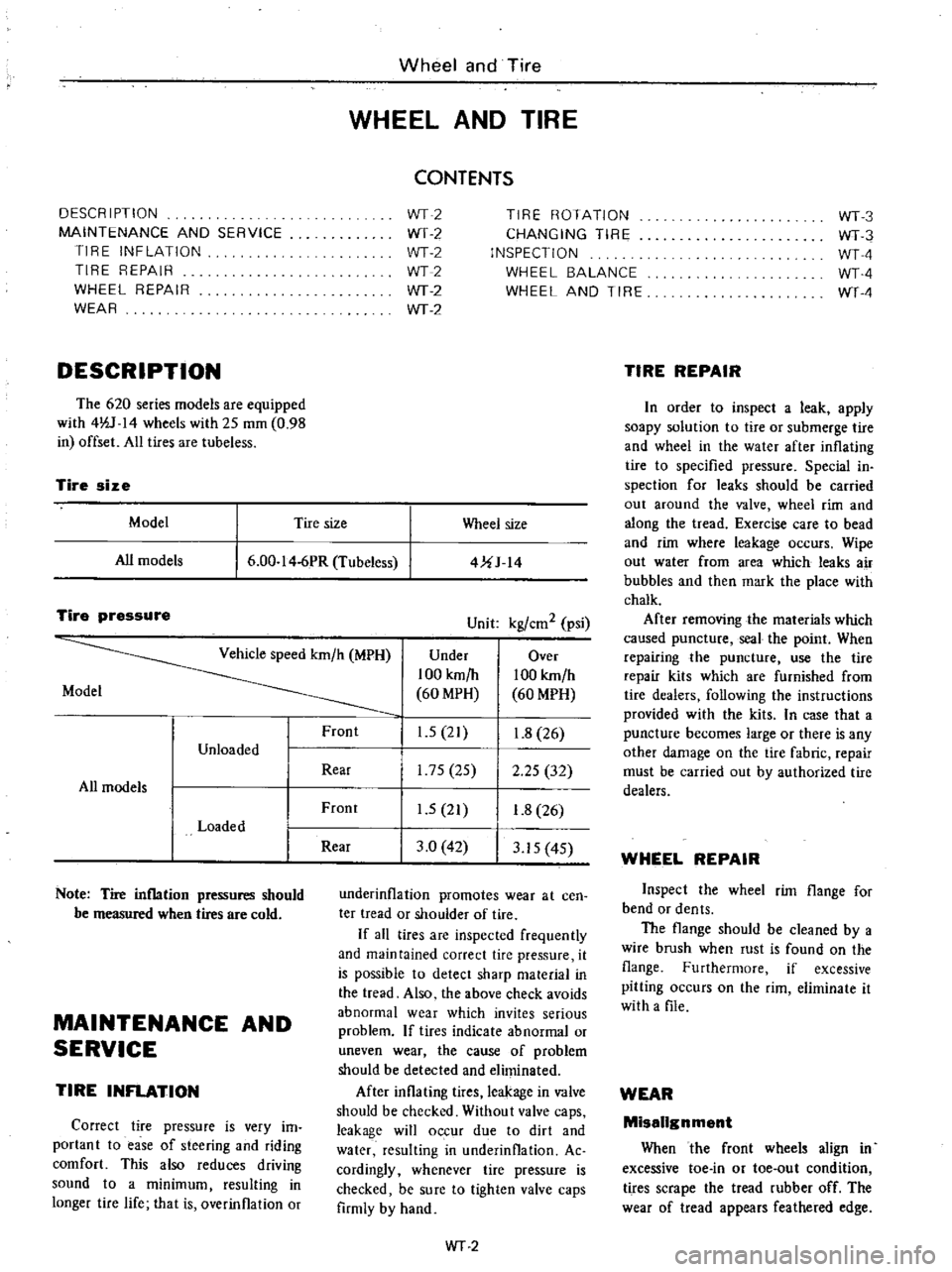
DESCRIPTION
MAINTENANCE
AND
SERVICE
TIRE
INFLATION
TIRE
REPAIR
WHEEL
REPAIR
WEAR
DESCRIPTION
The
620
series
models
are
equipped
with
4lV
14
wheels
with
25
mOl
0
98
in
offset
All
tires
are
tubeless
Wheel
and
Tire
WHEEL
AND
TIRE
CONTENTS
WT2
WT
2
WT2
WT2
WT
2
WT
2
TIRE
ROTATION
CHANGING
TIRE
INSPECTION
WHEEL
BALANCE
WHEEL
AND
TIRE
Tire
size
Model
Tire
size
Wheel
size
All
models
6
00
I
4
6PR
Tubeless
4UJ
14
Tire
pressure
Unit
kgl
em
2
psi
Vehicle
speed
km
h
MPH
Under
Over
100
km
h
100
km
h
Model
60
MPH
60
MPH
Front
1
5
21
1
8
26
Unloaded
Rear
175
25
2
25
32
All
models
Front
1
5
21
1
8
26
Loaded
Rear
3
0
42
3
15
4S
Note
Tire
inflation
pressures
should
be
measured
when
tires
are
cold
MAINTENANCE
AND
SERVICE
TIRE
INFLATION
Correct
tire
pressure
is
very
im
portant
to
ease
of
steering
and
riding
comfort
This
also
reduces
driving
sound
to
a
minimum
resulting
in
longer
tire
life
that
is
overinflation
or
underinflation
promotes
wear
at
cen
ter
tread
or
shouider
of
tire
If
aU
tires
are
inspected
frequently
and
maintained
correct
tire
pressure
it
is
possible
to
detect
sharp
material
in
the
tread
Also
the
above
check
avoids
abnormal
wear
which
invites
serious
problem
If
tires
indicate
abnormal
or
uneven
wear
the
cause
of
problem
should
be
detected
and
eliminated
After
inflating
tires
leakage
in
valve
should
be
checked
Without
valve
caps
leakage
will
occur
due
to
dirt
and
water
resulting
in
underinflation
Ac
cordingly
whenever
tire
pressure
is
checked
be
sure
to
tighten
valve
caps
firmly
by
hand
WT
2
WT3
WT3
WTA
WTA
WT
4
TIRE
REPAIR
In
order
to
inspect
a
leak
apply
soapy
solution
to
tire
or
submerge
tire
and
wheei
in
the
water
after
inflating
tire
to
specified
pressure
Special
in
spection
for
leaks
should
be
carried
out
around
the
valve
wheel
rim
and
along
the
tread
Exercise
care
to
bead
and
rim
where
leakage
occurs
Wipe
out
water
from
area
which
leaks
air
bubbles
and
then
mark
the
place
with
chalk
After
removing
the
materials
which
caused
puncture
seal
the
point
When
repairing
the
puncture
use
the
tire
repair
kits
which
are
furnished
from
tire
dealers
following
the
instructions
provided
with
the
kits
In
case
that
a
puncture
becomes
large
or
there
is
any
other
damage
on
the
tire
fabric
repair
must
be
carried
out
by
authorized
tire
dealers
WHEEL
REPAIR
Inspect
the
wheel
rim
flange
for
bend
or
dents
The
flange
should
be
cleaned
by
a
wire
brush
when
rust
is
found
on
the
flange
Furthermore
if
excessive
pitting
occurs
on
the
rim
eliminate
it
with
a
file
WEAR
Missilgnment
When
the
front
wheels
align
in
excessive
toe
in
or
toe
out
condition
tires
scrape
the
tread
rubber
off
The
wear
of
tread
appears
feathered
edge
Page 403 of 537
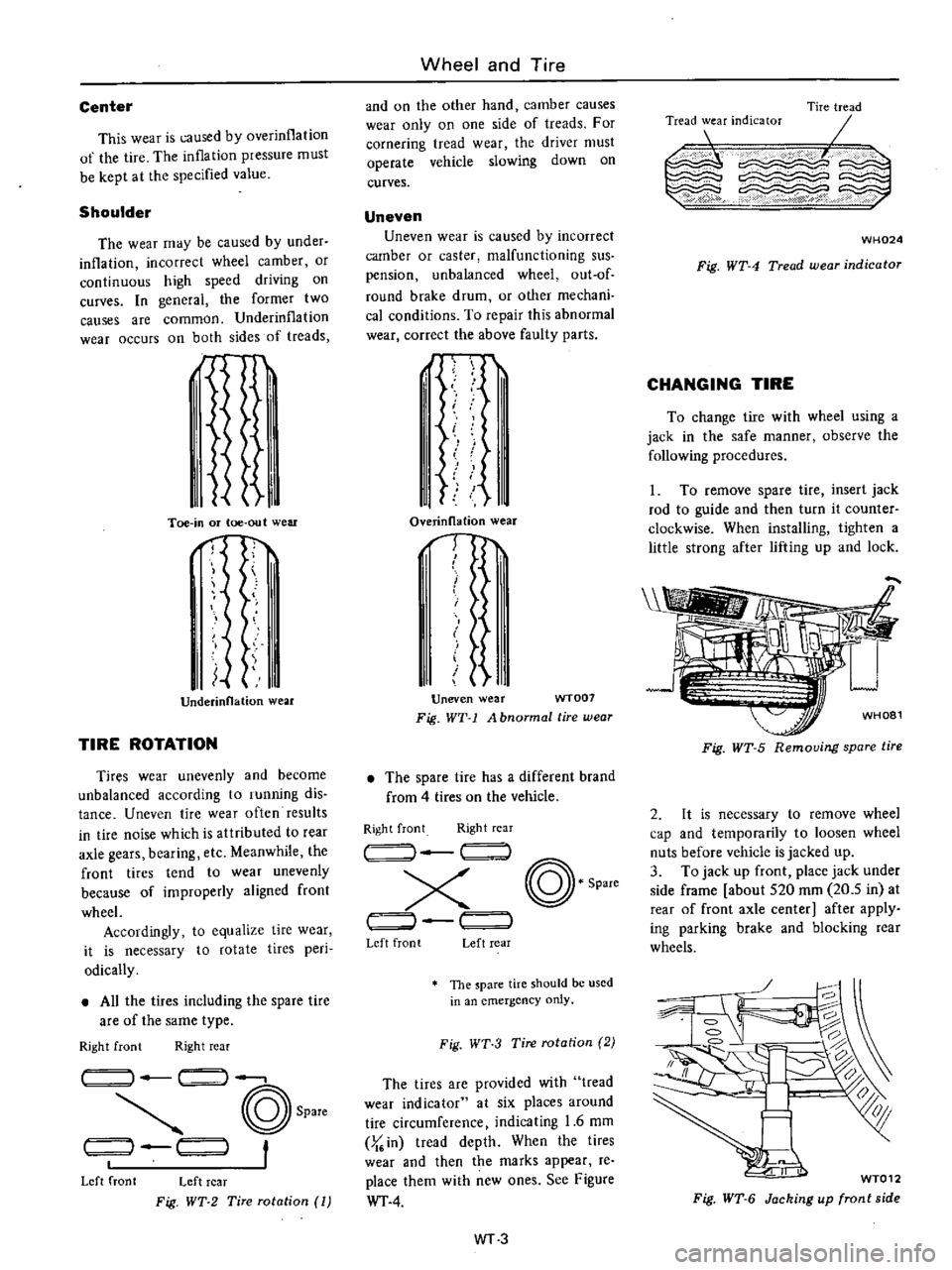
Center
This
wear
is
caused
by
overinflation
of
the
tire
The
inflation
pressure
must
be
kept
at
the
specified
value
Shoulder
The
wear
may
be
caused
by
under
inflation
incorrect
wheel
camber
or
continuous
high
speed
driving
on
curves
In
general
the
former
two
causes
are
common
Underinflation
wear
occurs
on
both
sides
of
treads
d
I
Ii
Toe
in
or
toe
out
wear
nf
I
Underinnation
wear
TIRE
ROTATION
Tires
wear
unevenly
and
become
unbalanced
according
to
running
dis
tance
Uneven
tire
wear
often
results
in
tire
noise
which
is
attributed
to
rear
axle
gears
bearing
etc
Meanwhile
the
front
tires
tend
to
wear
unevenly
because
of
improperly
aligned
front
wheel
Accordingly
to
equalize
tire
wear
it
is
necessary
to
rotate
tires
peri
odically
All
the
tires
including
the
spare
tire
are
of
the
same
type
Right
front
Right
rear
14
1
I
@
Spare
t
t
1
1
Left
front
Left
rear
Fig
WT
2
Tire
rotation
1
Wheel
and
Tire
and
on
the
other
hand
camber
causes
wear
only
on
one
side
of
treads
For
cornering
tread
wear
the
driver
must
operate
vehicle
slowing
down
on
curves
Uneven
Uneven
wear
is
caused
by
incorrect
camber
or
caster
malfunctioning
sus
pension
unbalanced
wheel
out
of
round
brake
drum
or
other
mechani
cal
conditions
To
repair
this
abnormal
wear
correct
the
above
faulty
parts
J
I
II
i
11
I
1
Overinllation
wear
1
I
I
t
Uneven
wear
WT007
Fig
WT
1
A
bnormal
tire
wear
The
spare
lire
has
a
different
brand
from
4
tires
on
the
vehicle
Right
front
Right
rear
I
@
Spare
x
J
r
Left
front
Left
rear
The
pare
tire
should
be
used
in
an
emergency
only
Fig
WT
3
Tire
rotation
2
The
tires
are
provided
with
tread
wear
indicator
at
six
places
around
tire
circumference
indicating
1
6
mm
J
in
tread
depth
When
the
tires
wear
and
then
the
marks
appear
re
place
them
with
new
ones
See
Figure
WT
4
WT3
Tire
tread
0E
I
Tread
wear
indicator
c
WH024
Fig
WT
4
Tread
wear
indicator
CHANGING
TIRE
To
change
tire
with
wheel
using
a
jack
in
the
safe
manner
observe
the
following
procedures
1
To
remove
spare
tire
insert
jack
rod
to
guide
and
then
turn
it
counter
clockwise
When
installing
lighten
a
little
strong
after
lifting
up
and
lock
Fig
WT
5
Removing
spare
tire
2
It
is
necessary
to
remove
wheel
cap
and
temporarily
to
loosen
wheel
nuts
before
vehicle
is
jacked
up
3
To
jack
up
front
place
jack
under
side
frame
about
S20
mOl
20
5
in
at
rear
of
front
axle
center
after
apply
ing
parking
brake
and
blocking
rear
wheels
g
1
WT012
Fig
WT
6
Jacking
up
front
side
Page 414 of 537
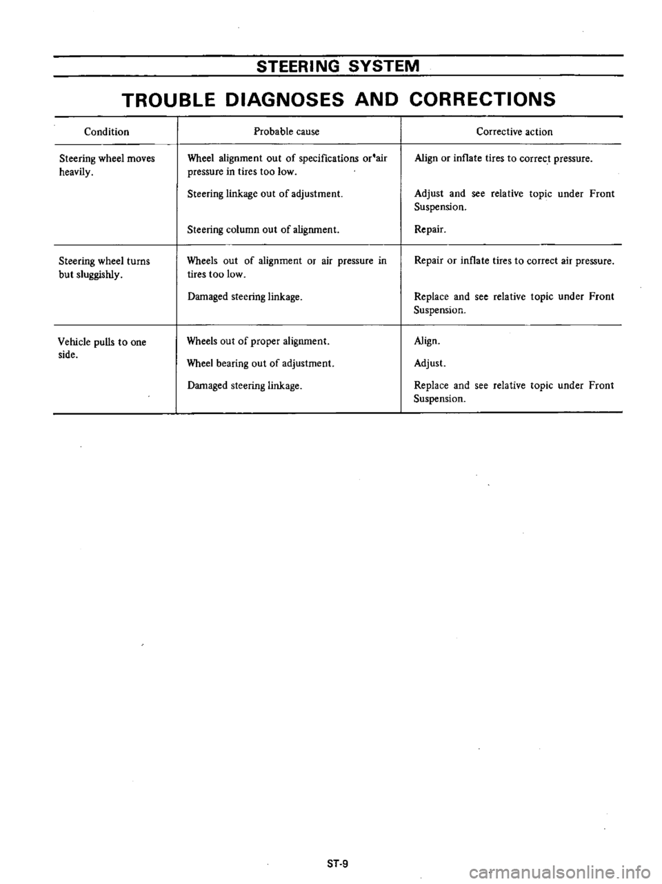
STEERING
SYSTEM
TROUBLE
DIAGNOSES
AND
CORRECTIONS
Condition
Steering
wheel
moves
heavily
Steering
wheel
turns
but
sluggishly
Vehicle
pulls
to
one
side
Probable
cause
Wheel
alignment
out
of
specifications
or
air
pressure
in
tires
too
low
Steering
linkage
out
of
adjustment
Steering
column
out
of
alignment
Wheels
out
of
alignment
or
air
pressure
in
tires
too
low
Damaged
steering
linkage
Wheels
out
of
proper
alignment
Wheel
bearing
out
of
adjustment
Damaged
steering
linkage
ST
9
Corrective
action
Align
or
inflate
tires
to
correct
pressure
Adjust
and
see
relative
topic
under
Front
Suspension
Repair
Repair
or
inflate
tires
to
correct
air
pressure
Replace
and
see
relative
topic
under
Front
Suspension
Align
Adjust
Replace
and
see
relative
topic
under
Front
Suspension
Page 451 of 537
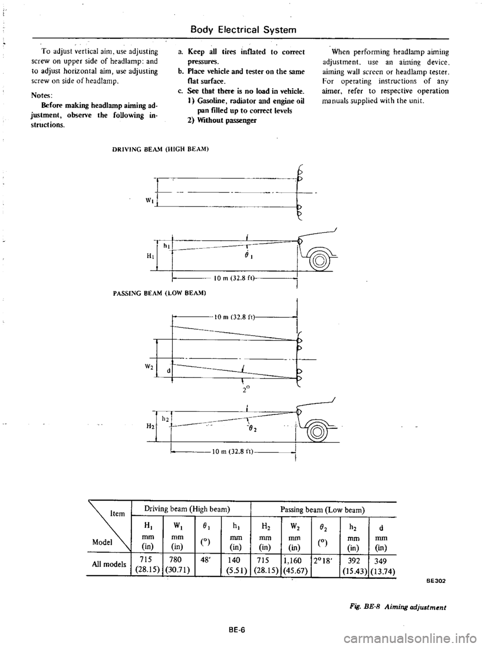
To
adjust
vertical
aim
use
adjusting
screw
on
upper
side
of
headlamp
and
to
adjust
horizontal
aim
use
adjusting
screw
on
side
of
head
lamp
Notes
Before
making
headlarnp
aiming
ad
justment
observe
the
foUowing
in
structions
Body
Electrical
System
a
Keep
aU
tires
inflated
to
correct
pressures
b
Place
vehicle
and
tester
on
the
same
flat
surface
c
See
that
there
is
no
load
in
vehicle
I
Gasoline
radiator
and
engine
oil
pan
filled
up
to
correct
levels
2
Without
passenger
When
performing
headlamp
aiming
adjustment
use
an
aiming
device
aiming
wall
screen
or
headlamp
tester
For
operating
instructions
of
any
aimer
refer
to
respective
operation
manuals
supplied
with
the
unit
DRIVING
BEAM
HIGH
BEAM
L
wt
H
G
hi
i
iiI
PASSING
BEAM
LOW
BEAM
10
m
32
8
ft
W2
H2
10
m
02
8
n
d
20
h2
I
02
I
I
f
10
m
32
8
ft
Driving
beam
High
beam
Passing
beam
Low
beam
HI
WI
01
mm
mm
CO
in
in
I
715
780
48
All
models
28
15
30
71
hI
H2
W2
h2
O2
d
mm
mm
mm
in
in
in
0
140
I
715
11
160
12018
5
51
28
15
45
67
mm
mm
in
in
392
349
is
43
13
74
BE302
Fig
BE
8
Aiming
adjustment
BE
6