set clock DATSUN PICK-UP 1977 Service Manual
[x] Cancel search | Manufacturer: DATSUN, Model Year: 1977, Model line: PICK-UP, Model: DATSUN PICK-UP 1977Pages: 537, PDF Size: 35.48 MB
Page 24 of 537
r
connected
hose
to
prevent
dust
from
entering
To
air
check
valve
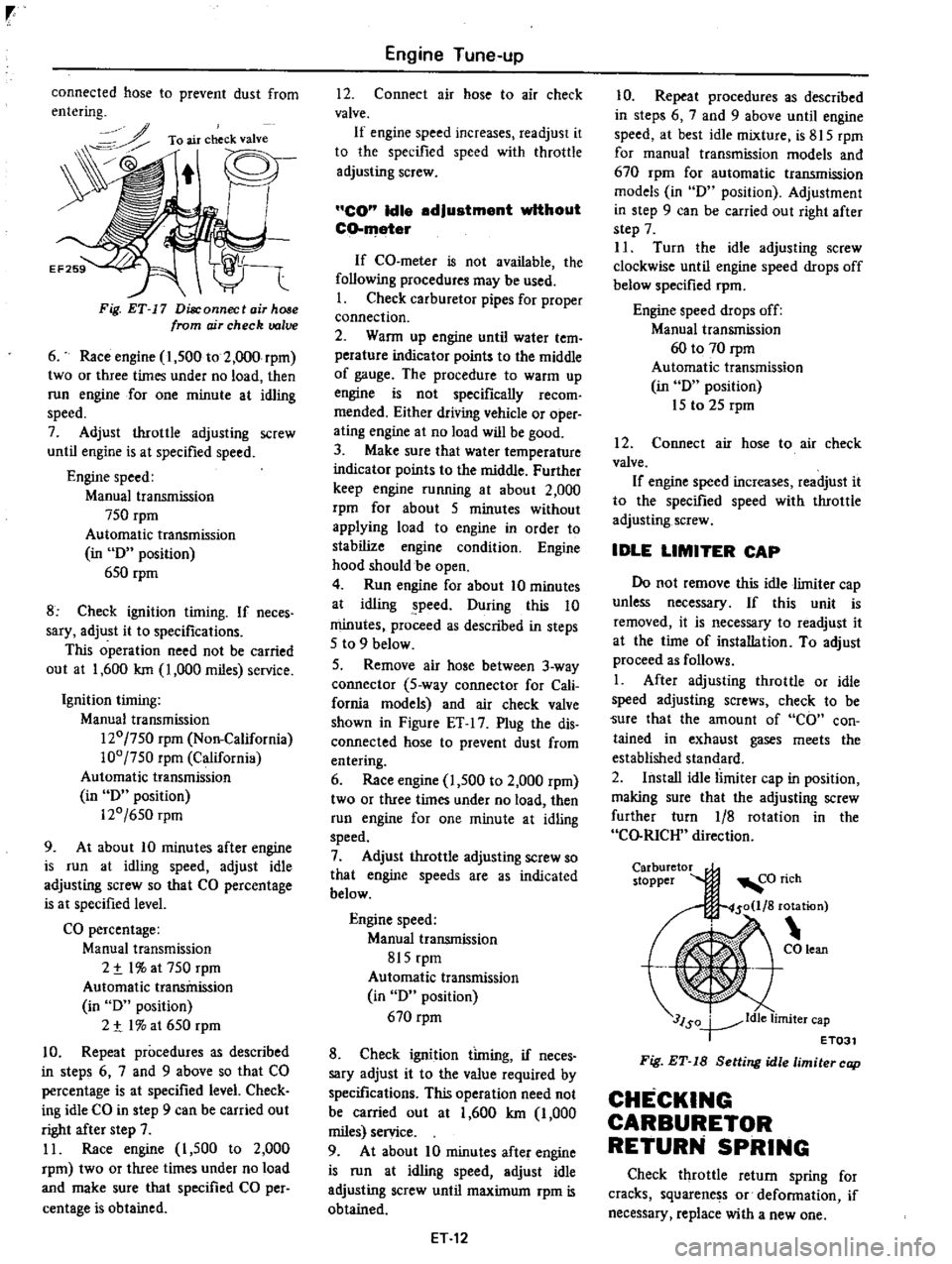
Fig
ET
17
Disconnect
air
hose
from
ojr
check
valve
6
Race
engine
1
500
to
2
000
rpm
two
or
three
times
under
no
load
then
run
engine
for
one
minute
at
idling
speed
7
Adjust
throttle
adjusting
screw
until
engine
is
at
specified
speed
Engine
speed
Manual
transmission
750
rpm
Automatic
transmission
in
D
position
650
rpm
8
Check
ignition
timing
If
neces
sary
adjust
it
to
specifications
This
operation
need
not
be
carried
out
at
1
600
Ian
1
000
miles
service
Ignition
timing
Manual
transmission
120
750
rpm
Non
California
100
750
rpm
California
Automatic
transmission
in
D
position
120
650
rpm
9
At
about
10
minutes
after
engine
is
run
at
idling
speed
adjust
idle
adjusting
screw
so
that
CO
percentage
is
at
specified
level
CO
percentage
Manual
transmission
2
t
I
at
750
rpm
Automatic
transmission
in
D
position
2
t
I
at
650
rpm
10
Repeat
procedures
as
described
in
steps
6
7
and
9
above
so
that
CO
percentage
is
at
specified
level
Check
ing
idle
CO
in
step
9
can
be
carried
out
right
after
step
7
11
Race
engine
I
500
to
2
000
rpm
two
or
three
times
under
no
load
and
make
sure
that
specified
CO
per
centage
is
obtained
Engine
Tune
up
12
Connect
air
hose
to
air
check
valve
If
engine
speed
increases
readjust
it
to
the
specified
speed
with
throttle
adjusting
screw
CO
Idle
adjustment
without
CO
meter
If
CO
meter
is
not
available
the
following
procedures
may
be
used
I
Check
carburetor
pipes
for
proper
connection
2
Wann
up
engine
until
water
tern
perature
indicator
points
to
the
middle
of
gauge
The
procedure
to
warm
up
engine
is
not
specifically
recom
mended
Either
driving
vehicle
or
oper
ating
engine
at
no
load
will
be
good
3
Make
sure
that
water
temperature
indicator
points
to
the
middle
Further
keep
engine
running
at
about
2
000
rpm
for
about
5
minutes
without
applying
load
to
engine
in
order
to
stabilize
engine
condition
Engine
hood
should
be
open
4
Run
engine
for
about
10
minutes
at
idling
peed
During
this
10
minutes
proceed
as
described
in
steps
5
to
9
below
5
Remove
air
hose
between
3
way
connector
5
way
connector
for
Cali
fornia
modeis
and
air
check
valve
shown
in
Figure
ET
17
Plug
the
dis
connected
hose
to
prevent
dust
from
entering
6
Race
engine
1
500
to
2
000
rpm
two
or
three
times
under
no
load
then
run
engine
for
one
minute
at
idling
speed
7
Adjust
throttle
adjusting
screw
so
that
engine
speeds
are
as
indicated
below
Engine
speed
Manual
transmission
815
rpm
Automatic
transmission
in
D
position
670
rpm
8
Check
ignition
timing
if
neces
sary
adjust
it
to
the
value
required
by
specifications
This
operation
need
not
be
carried
out
at
1
600
Ian
1
000
miles
service
9
At
about
10
minutes
after
engine
is
run
at
idling
speed
adjust
idle
adjusting
screw
until
maximum
rpm
is
obtained
ET
12
10
Repeat
procedures
as
described
in
steps
6
7
and
9
above
until
engine
speed
at
best
idle
mixture
is
815
rpm
for
manual
transmission
models
and
670
rpm
for
automatic
transmission
models
in
D
position
Adjustment
in
step
9
can
be
carried
out
right
after
step
7
II
Turn
the
idle
adjusting
screw
clockwise
until
engine
speed
drops
off
below
specified
rpm
Engine
speed
drops
off
Manual
transmission
60
to
70
rpm
Automatic
transmission
in
D
position
15
to
25
rpm
12
Connect
air
hose
to
air
check
valve
If
engine
speed
increases
readjust
it
to
the
specified
speed
with
throttle
adjusting
screw
IDLE
LIMITER
CAP
Do
not
remove
this
idle
limiter
cap
unless
necessary
If
this
unit
is
removed
it
is
necessary
to
readjust
it
at
the
time
of
installation
To
adjust
proceed
as
follows
1
After
adjusting
throttle
or
idle
speed
adjusting
screws
check
to
be
Sure
that
the
amount
of
CO
con
tained
in
exhaust
gases
meets
the
established
standard
2
Install
idle
limiter
cap
in
position
making
sure
that
the
adjusting
screw
further
turn
1
8
rotation
in
the
CO
RICH
direction
Carburetor
stopper
3lSo
ldle
limiter
cap
T
ET031
Fig
ET
18
Setting
idle
limiter
cap
CHECKING
CARBURETOR
RETURN
SPRING
Check
throttle
return
spring
for
cracks
squarene
s
or
defonnation
if
necessary
replace
with
a
new
one
Page 30 of 537
r
ADJUSTMENT
OF
SET
PRESSURE
OF
BOOST
CONTROLLED
DECELERATION
DEVICE
B
C
D
D
Generally
it
is
unnecessary
to
ad
just
the
B
C
D
D
however
if
it
should
become
necessary
to
adjust
it
the
procedure
is
as
follows
Prepare
the
foUowlnB
tools
I
Tachometer
to
measure
the
en
gine
speed
while
idling
and
a
screw
driver
2
A
vacuum
gauge
connecting
pipe
Note
A
qui
k
response
type
boost
gauge
such
as
Bourdon
s
type
is
recommended
a
mercury
type
manometer
should
not
be
used
To
properly
set
the
B
C
D
D
set
pressure
proceed
as
follows
I
Remove
the
harness
of
solenoid
valve
TO
D
D
solenrod
VT
FJ
1
B
C
D
D
solenni
valve
harness
J
ri
y
EF262
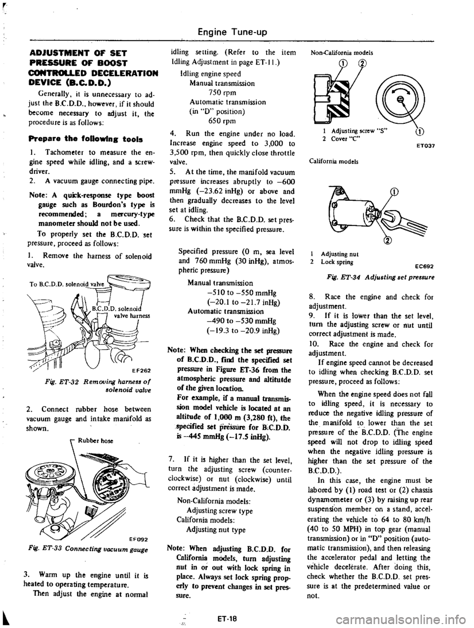
F
g
ET
32
Removing
harneS5
of
solenoid
valve
2
Connect
rubber
hose
between
vacuum
gauge
and
intake
manifold
as
shown
Fig
ET
33
Connecting
vacuum
gauge
3
Warm
up
the
engine
until
it
is
heated
to
operating
temperature
Then
adjust
the
engine
at
normal
Engine
Tune
up
idling
setting
Refer
to
the
item
Idling
Adjustment
in
page
ET
II
Idling
engine
speed
Manual
transmission
750
rpm
Automatic
transmission
in
D
position
650
rpm
4
Run
the
engine
under
no
load
Increase
engine
speed
to
3
000
to
3
500
rpm
then
quickly
close
throttle
valve
5
At
the
time
the
manifold
vacuum
pressure
increases
abruptly
to
600
mmHg
23
62
inHg
or
above
and
then
gradually
decreases
to
the
level
set
at
idling
6
Check
that
the
B
C
D
D
set
pres
sure
is
within
the
specified
pressure
Specified
pressure
0
m
sea
level
and
760
mmHg
30
inHg
atmos
pheric
pressure
Manual
transmission
510
to
550
mmHg
20
1
to
21
7
inHg
Automatic
transmission
490
to
530
mmHg
19
3
to
20
9
inHg
Note
When
checking
the
set
pressure
of
B
C
D
D
find
the
specified
set
pressure
in
Figure
IT
36
from
the
atmospheric
pressure
and
altitutde
of
the
given
location
For
example
if
a
manual
transmis
sion
model
vehicle
is
located
at
an
altitude
of
1
000
m
3
280
ft
the
specified
set
preSsure
for
B
C
D
D
445
mmHg
17
5
inHg
7
If
it
is
higher
than
the
set
level
turn
the
adjusting
screw
counter
clockwise
or
nut
clockwise
until
correct
adjustment
is
made
Non
California
models
Adjusting
screw
type
California
models
Adjusting
nut
type
Note
When
adjusting
B
C
D
D
for
California
models
turn
adjusting
nut
in
or
out
with
lock
spring
in
place
Always
set
lock
spring
prop
erly
to
prevent
changes
in
set
pres
sure
ET
18
Non
california
models
1
Adjusting
screw
2
Cover
e
ET037
California
models
r
1
Adjusting
nut
2
Lock
spring
EC692
Fig
ET
34
Adjusting
Bet
pressure
8
Race
the
engine
and
check
for
adjustment
9
If
it
is
lower
than
the
set
level
turn
the
adjusting
screw
or
nut
until
correct
adjustment
is
made
10
Race
the
engine
and
check
for
adjustment
If
engine
speed
cannot
be
decreased
to
idling
when
checking
B
C
D
D
set
pressure
proceed
as
follows
When
the
engine
speed
does
not
fall
to
idling
speed
it
is
necessary
to
reduce
the
negative
idling
pressure
of
the
manifold
to
lower
than
the
set
pressure
of
the
B
C
D
D
The
engine
speed
will
not
drop
to
idling
speed
when
the
negative
idling
pressure
is
higher
than
the
set
pressure
of
the
B
C
D
D
In
this
case
the
engine
must
be
labored
by
I
road
test
or
2
chassis
dynamometer
or
3
by
raising
up
rear
suspension
member
on
a
stand
accel
erating
the
vehicle
to
64
to
80
krn
h
40
to
50
MPH
in
top
gear
manual
transmission
or
in
D
position
auto
matic
transmission
and
then
releasing
the
accelerator
pedal
and
letting
the
vehicle
decelerate
After
doing
this
check
whether
the
B
C
D
D
set
pres
sure
is
at
the
predetermined
value
or
not
Page 91 of 537
DESCRIPTION
COOLANT
LEVEL
DRAINING
AND
FLUSHING
THE
COOLING
SYSTEM
WATER
PUMP
REMOVAL
AND
INSTALLATION
DISASSEMBLY
INSPECTION
AND
ADJUSTMENT
TORQUE
COUPLING
REMOVAL
AND
INSTALLATION
DESCRIPTION
The
cooling
system
is
of
the
con
ventional
pressure
type
A
centrifugal
pump
installed
on
the
timing
chain
cover
serves
to
circulate
the
coolant
The
pressure
type
radiator
filler
cap
installed
on
the
radiator
operates
the
cooling
system
at
higher
than
atmos
pheric
pressure
The
higher
pressure
raises
the
boiling
point
of
the
coolant
and
in
Cooling
System
COOLING
SYSTEM
CONTENTS
CO
2
CO
2
OISASSEMBL
Y
INSPECTION
TEM
COUPLlNG
INSPECTION
THERMOSTAT
REMOVAL
AND
INSTALLATION
INSPECTION
RADIATOR
REMOVAL
AND
INSTALLATION
INSPECTION
CO
2
CO
2
CO
3
CO
3
CO
3
CO
3
CO
4
creases
the
cooling
efficiency
of
the
radiator
When
the
thermostat
is
closed
the
coolant
remains
in
the
cylinder
head
and
block
for
swift
warming
up
of
the
engine
After
it
reaches
normal
oper
ating
temperature
the
coolant
circu
lates
through
the
radiator
The
cooling
fan
drive
is
of
a
coupling
type
COOLANT
LEVEL
The
coolant
level
should
be
check
ed
and
maintained
at
SO
mm
1
97
in
below
the
upper
face
of
filler
neck
when
the
engine
is
cold
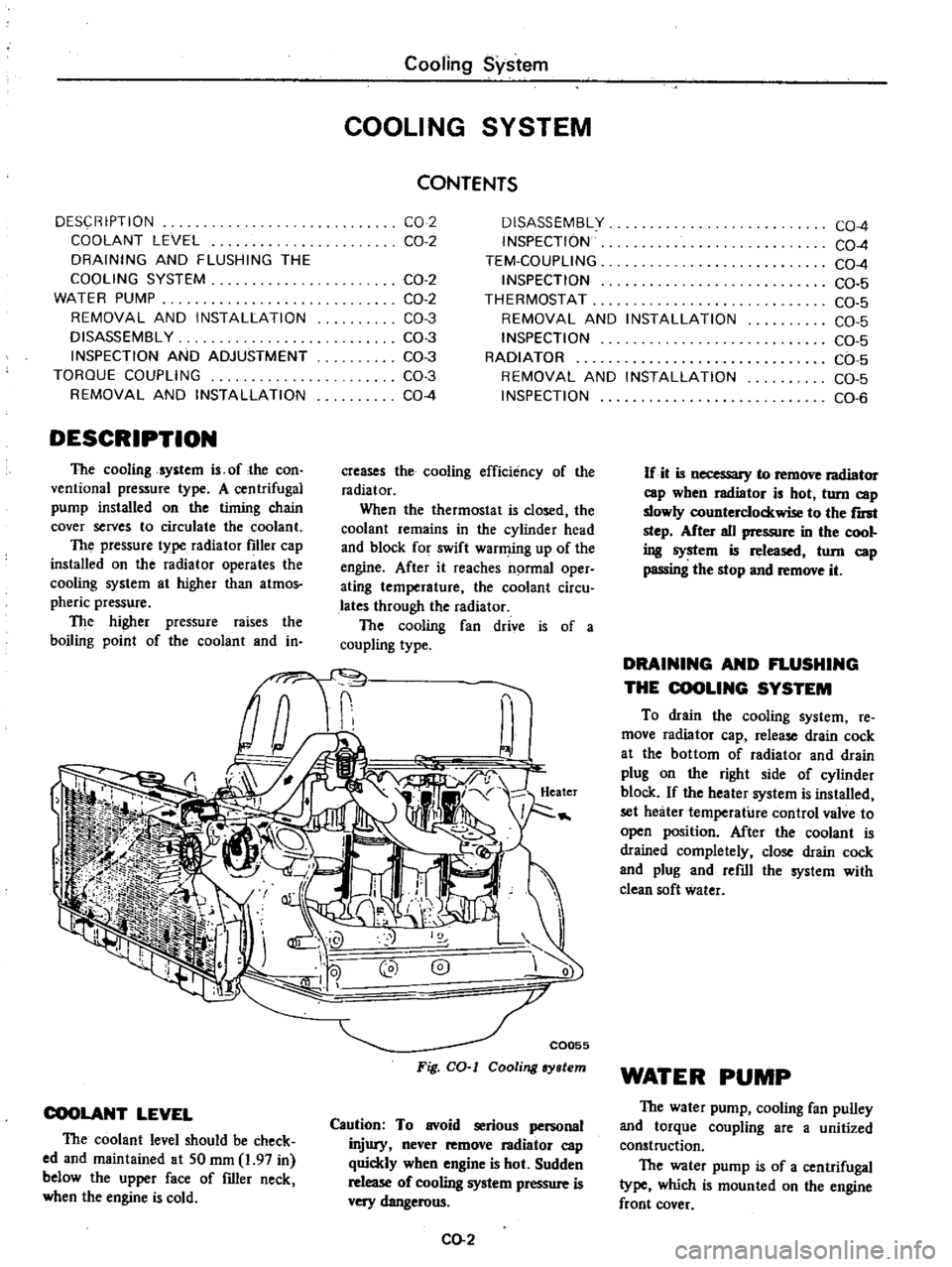
C0055
Fig
CO
I
Cooling
ry
lem
Caution
To
avoid
serious
personal
injury
never
remove
I3diator
cap
quickly
when
engine
is
hot
Sudden
release
of
cooling
system
pressure
is
very
dangerous
CO
2
CO
4
CO
4
CO
4
CO
5
CO
5
CO
5
CO
5
CO
5
CO
5
CO
6
If
it
is
necessary
to
remove
radiator
cap
wben
radiator
is
hot
turn
cap
slowly
counterclockwise
to
the
r
step
After
all
pressure
in
the
cool
ing
system
is
released
tom
cap
passing
the
stop
and
remove
it
DRAINING
AND
FLUSHING
THE
COOLING
SYSTEM
To
drain
the
cooling
system
re
move
radiator
cap
release
drain
cock
at
the
bottom
of
radiator
and
drain
plug
on
the
right
side
of
cylinder
block
If
the
heater
system
is
installed
set
heater
temperature
control
valve
to
open
position
After
the
coolant
is
drained
completely
close
drain
cock
and
plug
and
refill
the
system
with
clean
soft
water
WATER
PUMP
The
water
pump
cooling
fan
pulley
and
torque
coupling
are
a
unitized
construction
The
water
pump
is
of
a
centrifugal
type
which
is
mounted
on
the
engine
front
cover
Page 118 of 537
rpm
two
or
three
iimes
under
no
load
and
make
sure
that
specified
CO
per
centage
is
obtained
12
Connect
air
hose
to
air
check
valve
If
engine
speed
increases
readjust
it
to
the
specified
speed
with
throttle
adjustingsqew
CO
idle
edJustment
without
CO
meter
If
CO
meter
is
not
available
the
following
procedures
may
be
used
L
Check
carburetor
pipes
for
proper
connection
2
Warm
up
engine
until
water
tem
perature
indicator
points
to
the
middle
of
gauge
The
procedure
to
warm
up
engine
is
not
specifically
recom
mended
Either
driving
vehicle
or
oper
ating
engine
at
no
load
will
be
good
3
Make
sure
that
water
temperature
indicator
points
to
the
middle
Further
keep
engine
running
at
about
2
000
rpm
for
about
5
minutes
without
applying
load
to
engine
in
order
to
stabilize
engine
condition
Engine
hood
should
be
open
4
Run
engine
for
about
10
minutes
at
idling
speed
During
this
10
minutes
proceed
as
described
in
steps
5
to
9
below
5
Remove
air
hose
between
3
way
connector
5
way
connector
for
Cali
fornia
models
and
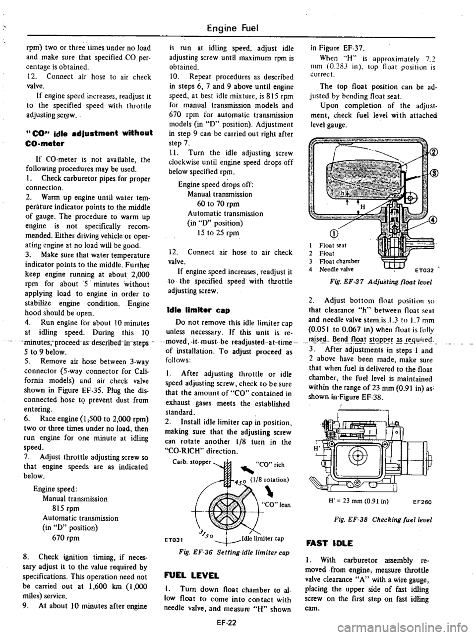
air
check
valve
shown
in
Figure
EF
35
Plug
the
dis
connected
hose
19
prevent
dust
from
entering
6
Race
engine
1
500
to
2
000
rpm
two
or
three
times
under
no
load
then
run
engine
for
one
minute
at
idling
speed
7
Adjust
throttle
adjusting
screw
so
that
engine
speeds
are
as
indicated
below
Engine
speed
Manual
transmission
815
rpm
Automatic
transmission
in
D
position
670
rpm
8
Check
ignition
timing
if
neces
sary
adjust
it
to
the
value
required
by
specifications
This
operation
need
not
be
carried
out
at
1
600
km
1
000
miles
service
9
At
about
10
minutes
after
engine
Engine
Fuel
is
run
at
idling
speed
adjust
idle
adjusting
screw
until
maximum
rpm
is
obtained
10
Repeat
procedures
as
described
in
steps
6
7
and
9
above
until
engine
speed
at
best
idle
mixture
is
815
rpm
for
manual
transmission
models
and
670
rpm
for
automatic
transmission
models
in
D
position
Adjustment
in
step
9
can
be
carried
out
right
after
step
7
11
Turn
the
idle
adjusting
screw
clockwise
until
engine
speed
drops
off
below
specified
rpm
Engine
speed
drops
off
Manual
transmission
60
to
70
rpm
Automatic
transmission
in
D
position
15
to
25
rpm
12
Connect
air
hose
to
air
check
valve
If
engine
speed
increases
readjust
it
to
the
specified
speed
with
throttle
adjusting
screw
Idle
limiter
cep
Do
not
remove
this
idle
limiter
cap
unless
necessary
If
this
unit
is
re
moved
it
must
be
readjusted
at
lime
of
installation
To
adjust
proceed
as
follows
I
After
adjusting
throttle
or
idle
speed
adjusting
screw
check
to
be
sure
that
the
amount
of
CO
contained
in
exhaust
gases
meets
the
established
standard
2
Install
idle
limiter
cap
in
position
making
sure
that
the
adjusting
screw
can
rotate
another
1
8
turn
in
the
CO
RICH
direction
Carbo
to
per
CO
rich
450
lIS
rotation
t
CO
lean
J
SQ
dl
lim
ET031
1
e
Iter
cap
Fig
EF
36
Setting
idle
limiter
cap
FUEL
LEVEL
1
Turn
down
float
chamber
to
al
low
float
to
come
into
contact
with
needle
valve
and
measure
Hu
shown
EF
22
in
Figu
re
EF
37
When
H
is
approximalely
7
mill
0
283
in
lOp
float
position
is
correct
The
top
float
position
can
be
ad
justed
by
bending
float
seat
Upon
completion
of
the
adjust
ment
check
fuel
level
wi
th
attached
level
gauge
p
j
i
I
it
I
Float
seat
2
Float
3
Float
chamber
4
Needle
valve
t
I
IIf
ET032
Fig
EF
37
Adjusting
float
level
2
Adjust
bottom
float
position
so
that
clearance
h
between
float
seat
and
needle
valve
stemis
I
3
to
L
7
mm
0
051
to
0
067
in
when
Iloat
is
fully
rals
n
Jloa
t
goppe
q
re
3
After
adjustments
in
steps
I
and
2
above
have
been
made
make
sure
that
when
fuel
is
delivered
to
the
float
chamber
the
fuel
level
is
maintained
within
the
range
of23
mm
0
91
in
as
shown
in
FigureEF
38
H
23
mm
0
91
in
EF260
Fig
EF
38
Checking
ruellevel
FAST
IDLE
I
With
carburetor
assembly
reo
moved
from
engine
measure
throttle
valve
clearance
A
with
a
wire
gauge
placing
the
upper
side
of
fast
idling
screw
on
the
first
step
on
fast
idling
cam
Page 123 of 537
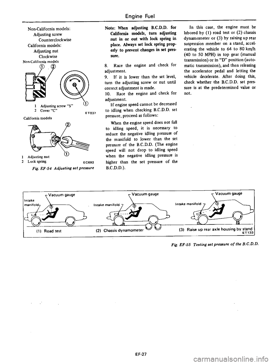
Non
California
models
Adjusting
screw
Counterclockwise
California
models
Adjusting
nut
Clockwise
Non
California
models
1
2
1
Adjusting
screw
s
2
Cover
e
California
models
t
1
Adjusting
nut
2
Lock
spring
EC692
Fig
EF
54
Adjusting
et
pressure
vacuum
gauge
Intake
gjl
11
Road
test
CD
ET037
Engine
Fuel
Note
When
adjusting
B
C
D
D
for
California
models
turn
adjusting
nut
in
or
out
with
lock
spring
in
place
Always
set
lock
spring
prop
erly
to
prevent
changes
in
set
pres
sure
8
Race
the
engine
and
check
for
adjustment
9
If
it
is
lower
than
the
set
level
turn
the
adjusting
screw
or
nut
until
correct
adjustment
is
made
10
Race
the
engine
and
check
for
adjustment
If
engine
speed
cannot
be
decreased
to
idling
when
checking
B
C
D
D
set
pressure
proceed
as
follows
When
the
engine
speed
does
not
fall
to
idling
speed
it
is
necessary
to
reduce
the
negative
idling
pressure
of
the
manifold
to
lower
than
the
set
pressure
of
the
B
C
D
O
The
engine
speed
will
not
drop
to
idling
speed
when
the
negative
idling
pressure
is
higher
Ihan
the
sel
pressure
of
the
B
C
O
O
acuum
gauge
Intakema
M
V
9iI
21
Chas
amomeler
In
this
case
the
engine
must
be
labored
by
I
road
test
or
2
chassis
dynamometer
or
3
by
raising
up
rear
suspension
member
on
a
stand
accel
erating
the
vehicle
to
64
to
80
km
h
40
10
50
MPH
in
top
gear
manual
transmission
or
in
0
position
auto
matic
transmission
and
then
releasing
the
accelerator
pedal
and
letting
the
vehicle
decelerate
After
doing
this
check
whether
the
B
C
O
D
set
pres
sure
is
at
the
predetermined
value
or
not
Vacuum
gauge
n
i
Y
3
Raise
up
rear
axle
housing
by
stand
ET133
Fig
EF
55
Testing
sel
pre
ure
of
the
B
C
D
D
EF
27
Page 190 of 537
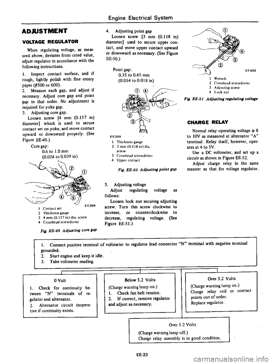
ADJUSTMENT
VOLTAGE
REGULATOR
When
regulating
voltage
as
meas
ured
above
deviates
from
rated
value
adjust
regulator
in
accordance
with
the
following
instructions
I
Inspect
contact
surface
and
if
rough
lightly
polish
with
fine
emery
paper
1
500
or
600
2
Measure
each
gap
and
adjust
if
necessary
Adjust
core
gap
and
point
gap
in
that
order
No
adjustment
is
required
for
yoke
gap
3
Adjusting
core
gap
Loosen
screw
4
mm
0
157
in
diameter
which
is
used
to
secure
contact
set
on
yoke
and
move
contact
upward
or
downward
properly
See
Figure
EE
49
Core
gap
0
6
to
1
0
mm
0
024
to
0
039
in
EE398
I
Contact
set
2
ThicknesJ
gauge
3
4
mm
0
157
in
dia
screw
4
Crosshead
Jcrewdriver
Fig
EE
49
AdjUJJting
core
gap
Engine
Electrical
System
4
Adjusting
point
gap
Loosen
screw
3
mm
O
lIS
in
diameter
used
to
secure
upper
con
tact
and
move
upper
contact
upward
or
downward
as
necessary
See
Figure
EE
50
Point
gap
035
to
0
45
mm
0
014
to
O
D1S
in
EE399
I
Thicknes
gauge
2
3
mm
0
118
in
dia
screw
3
Cro
Sshelld
screwdriver
4
Upper
contact
Fig
EE
50
Adjusting
point
gap
5
Adjusting
voltage
Adjust
regulating
voltage
as
follows
Loosen
lock
nut
securing
adjusting
screw
Turn
this
screw
clockwise
to
increase
or
counterclockwise
to
decrease
regulating
voltage
See
Figure
EE
5
J
CD
EE400
I
Wrench
2
Crosshead
screwdriver
3
Adjusting
screw
4
l
ock
nut
Fig
EE
51
AdjUJJting
rel
Ulating
voltage
CHARGE
RELAY
Nonna
relay
operating
voltage
is
S
to
IOV
as
measured
at
alternator
A
tenninal
Relay
itself
however
oper
ates
at
4
to
5V
Use
a
DC
voltmeter
and
set
up
a
circuit
as
shown
in
Figure
EE
52
Adjust
charge
relay
in
the
same
manner
as
that
for
voltage
regulator
L
Connect
positive
tenninal
of
voltmeter
to
regulator
lead
connector
N
tenninal
with
negative
terminal
grounded
2
Start
engine
and
keep
it
idle
3
Take
voltmeter
reading
o
Volt
I
Check
for
continuity
be
tween
terminals
of
re
gulator
and
alternator
2
Alternator
circuit
inopera
tive
if
continuity
exists
Below
5
2
Volts
Charge
warning
lamp
on
I
Check
fan
belt
tension
2
If
correct
remove
regulator
and
adjust
as
necessary
Over
5
2
Volts
Charge
warning
lamp
on
Charge
relay
coil
or
contact
points
out
of
order
Replace
regulator
Over
5
2
Volts
Charge
warning
lamp
off
Charge
relay
assembly
is
in
good
condition
EE
23
Page 203 of 537
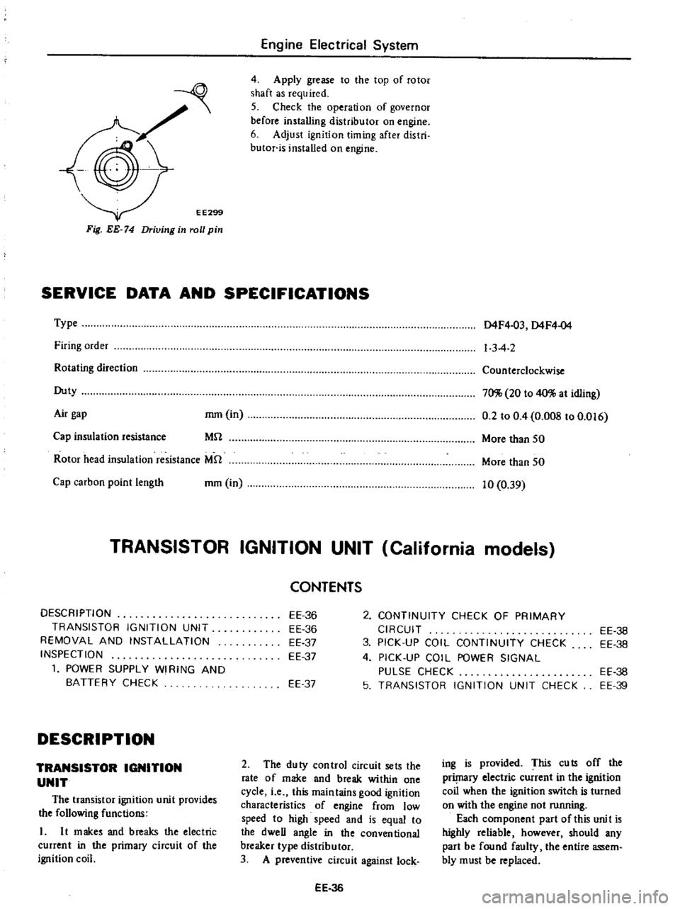
EE299
Fig
EE
74
Driving
in
roll
pin
Engine
Electrical
System
4
Apply
grease
to
the
top
of
rotor
shaft
as
required
5
Check
the
operation
of
governor
before
installing
distributor
on
engine
6
Adjust
ignition
timing
after
distri
butor
is
installed
on
engine
SERVICE
DATA
AND
SPECIFICATIONS
Type
Firing
order
Rotating
direction
Duty
Air
gap
mm
in
MU
Cap
insulation
resistance
Rotor
head
insulation
resistance
MU
Cap
carbon
point
length
mm
in
D4F4
03
D4F4
04
1
3
4
2
Counterclockwise
70
20
to
40
at
idling
0
2
to
0
4
O
OOS
to
0
016
More
than
50
More
than
50
10
0
39
TRANSISTOR
IGNITION
UNIT
California
models
DESCRIPTION
TRANSISTOR
IGNITION
UNIT
REMOVAL
AND
INSTALLATION
INSPECTION
1
POWER
SUPPLY
WI
RING
AND
BATTERY
CHECK
DESCRIPTION
TRANSISTOR
IGNITION
UNIT
The
transistor
ignition
unit
provides
the
following
functions
L
It
makes
and
breaks
the
electric
current
in
the
primacy
circuit
of
the
ignition
coil
2
CONTINUITY
CHECK
OF
PRIMARY
CIRCUIT
3
PICK
UP
COIL
CONTINUITY
CHECK
4
PICK
UP
COIL
POWER
SIGNAL
PULSE
CHECK
5
TRANSISTOR
IGNITION
UNIT
CHECK
CONTENTS
EE
36
EE
36
EE
37
EE
37
EE
37
2
The
duty
control
circuit
sets
the
rate
of
make
and
break
within
one
cycle
i
e
this
maintains
good
ignition
characteristics
of
engine
from
low
speed
to
high
speed
and
is
equal
to
the
dweU
angle
in
the
conventional
breaker
type
distributor
3
A
preventive
circuit
against
lock
EE
36
EE
36
EE
38
EE
38
EE
39
ing
is
provided
This
cuts
off
the
prilnaCY
electric
current
in
the
ignition
coil
when
the
ignition
switch
is
turned
on
with
the
engine
not
running
Each
component
part
of
this
unit
is
highly
reliable
however
should
any
part
be
found
faulty
the
entire
assem
bly
must
be
replaced
Page 409 of 537
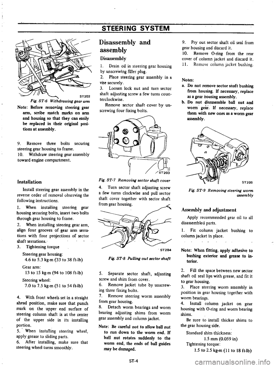
ST202
Fig
ST
6
Withdrawing
gear
ann
Note
Before
removing
steering
gear
arm
scribe
match
marks
on
arm
and
housing
so
that
they
can
easily
be
replaced
in
their
original
posi
tions
at
assembly
9
Remove
three
bolts
securing
steering
gear
housing
to
frame
10
Withdraw
steering
gear
assembly
toward
engine
compartment
Installation
Install
steering
gear
assembly
in
the
reverse
order
of
removal
observing
the
following
instructions
I
When
installing
steering
gear
housing
securing
bolts
insert
two
bolts
through
gear
housing
to
frame
2
When
installing
steering
gear
arm
align
four
grooves
of
gear
arm
serra
tions
with
four
projections
of
sector
shaft
serrations
3
Tightening
torque
Steering
gear
housing
4
6
to
S
3
kg
m
33
to
38
ft
lb
Gear
arm
13
to
IS
kg
m
94
to
108
ft
lb
Steering
wheel
7
0
to
7
S
kg
m
51
to
54
ft
Ib
4
With
front
wheels
set
in
a
straight
ahead
position
make
sure
that
punch
mark
on
the
upper
end
surface
of
steering
column
shaft
is
at
the
center
of
the
upper
side
in
its
installing
portion
S
When
installing
steering
wheel
apply
grease
to
sliding
parts
6
After
installing
make
sure
that
steering
wheel
turns
smoothly
STEERING
SYSTEM
Disassembly
and
assembly
Disassembly
I
Drain
oil
in
steering
gear
housing
by
unscrewing
fIller
plug
2
Place
steering
gear
assembly
in
a
vise
securely
3
Loosen
lock
nut
and
turn
sector
shaft
adjusting
screw
a
few
turns
coun
terclockwise
Remove
sector
shaft
cover
by
un
screwing
four
fixing
bolts
rn
ST203
Fig
ST
7
Remouing
sector
haft
couer
4
Turn
sector
shaft
adjusting
screw
a
few
turns
clockwise
and
pull
sector
shaft
cover
together
with
sector
shaft
from
gear
housing
ST204
Fig
ST
B
PuUing
out
ector
haft
S
Separate
sector
shaft
adjusting
screw
and
shim
from
cover
6
Remove
jacket
tube
by
unscrew
ing
three
fixing
bolts
7
Remove
steering
worm
assembly
from
gear
housing
8
Detach
worm
bearings
and
worm
bearing
adjusting
shims
from
worm
gear
assembly
and
column
jacket
Note
Be
careful
not
to
allow
ball
nut
to
run
down
to
the
worm
end
If
ball
nut
rotates
suddenly
to
the
worm
end
the
ends
of
ball
guides
may
be
damaged
ST
4
9
Pry
out
sector
shaft
oil
seal
from
gear
housing
and
discard
it
10
Remove
O
ring
from
the
rear
cover
of
column
jacket
and
discard
it
11
Remove
column
jacket
bushing
Notes
a
Do
not
remove
sector
shaft
bushing
from
housing
If
necessary
replace
as
a
gea2
nousing
assembly
b
Do
not
disassemble
ball
nut
and
worm
geir
If
necessary
replace
them
with
new
ones
as
a
worm
gear
assembly
Fig
ST
9
Removing
steering
worm
assem
bly
Assembly
and
adjustment
Apply
recommended
gear
oil
to
all
disassembled
parts
1
Fit
column
jacket
bushing
to
column
jacket
in
place
Note
When
fitting
apply
adhesive
to
bushing
exterior
and
grease
to
in
terior
2
Fill
the
space
between
new
sector
shaft
oil
seal
lips
with
grease
and
fit
it
to
gear
housing
3
Place
steering
worm
assembly
in
position
in
gear
housing
together
with
worm
bearings
4
Install
column
jacket
on
gear
housing
with
O
ring
and
worm
bearing
shims
Be
sure
to
install
thicker
shims
to
the
gear
housing
side
Standard
shim
thickness
1
5
mOl
0
OS9
in
Tightening
torque
1
5
to
2
S
kg
m
11
to
18
ft
Ib
Page 461 of 537
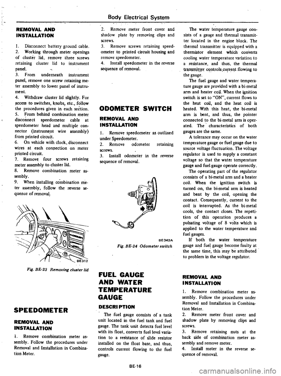
REMOVAL
AND
INSTALLATION
I
Disconnect
battery
ground
cable
2
Working
through
meter
openings
of
cluster
lid
remove
three
screws
retaining
cluster
lid
to
instrument
panel
3
From
underneath
instrument
panel
remove
one
screw
retaining
me
ter
assembly
to
lower
panel
of
instru
ment
4
Withdraw
cluster
lid
slightly
For
ccess
to
switches
knobs
etc
follow
the
procedures
given
in
each
section
5
From
behind
combination
meter
disconnect
speedometer
cable
at
speedometer
head
and
multiple
con
nector
instrume
nt
wire
assembly
from
printed
circuit
6
On
vehicle
with
clock
disconnect
wires
at
each
connection
on
meter
printed
circuit
7
Remove
four
screws
retaining
me
ter
assembly
to
cluster
lid
8
Remov
combination
meter
as
sembly
9
When
installing
combination
me
ter
assembly
follow
the
reverse
se
quence
of
removal
Fig
BE
23
Removing
eluster
lid
SPEEDOMETER
REMOVAL
AND
INSTALLATION
1
Remove
combination
meter
as
sembly
Follow
the
procedures
under
Removal
and
Installation
in
Combina
tion
Meter
Body
Electrical
System
2
Remove
meter
front
cover
and
shadow
plate
by
removing
clips
and
screws
3
Remove
screws
retaining
speed
ometer
to
printed
circuit
housing
and
remove
speedometer
4
Install
speedometer
in
the
reverse
sequence
of
removal
ODOMETER
SWITCH
REMOVAL
AND
INSTALLATION
I
Remove
speedometer
as
outlined
under
Speedometer
2
Remove
odometer
retaining
screws
3
Install
odometer
in
the
reverse
sequence
of
removal
BE342A
Fig
BE
24
Odometerswitch
FUEL
GAUGE
AND
WATER
TEMPERATURE
GAUGE
DESCRI
PTION
The
fuel
gauge
consists
of
a
tank
unit
located
in
the
fuel
tank
and
fuel
gauge
The
tank
unit
detects
fuel
level
with
its
float
converts
fuel
level
varia
tion
to
a
resistance
of
slide
resistor
installed
on
the
float
base
and
thus
controls
current
flowing
to
the
fuel
gauge
BE16
The
water
temperature
gauge
con
sists
of
a
gauge
and
thermal
transmit
ter
located
in
the
engine
block
The
thermal
transmitter
is
equipped
with
a
thermistor
element
which
converts
cooling
water
temperature
variation
to
a
resistance
and
thus
the
thermal
tr
t
c
rtrols
cUfTent
flowing
to
the
gauge
The
fuel
gauge
and
water
tempera
ture
gauge
are
provided
with
a
bi
metal
arm
and
heater
coil
When
the
ignition
switch
is
set
to
ON
current
flows
to
the
heat
coil
and
the
heat
coil
is
heated
With
this
heat
the
bi
metal
arm
is
bent
and
thus
the
pointer
connected
to
the
bi
metal
arm
is
oper
ated
The
characteristics
of
both
gauges
are
the
same
A
tolerance
may
occur
on
the
water
temperature
gauge
or
fuel
gauge
due
to
source
voltage
fluctuation
The
voltage
regulator
is
used
to
supply
a
constant
voltage
so
that
the
water
temperature
gauge
and
fuel
gauge
operate
correctly
The
operating
part
of
the
regulator
consists
of
a
bi
metal
arm
and
a
heater
coil
When
the
ignition
switch
is
turned
on
the
bi
metal
arm
is
heated
and
bent
by
the
coil
opening
the
contact
Consequently
current
to
the
coil
is
interrupted
As
the
bi
metal
cools
the
contact
closes
The
repeti
tion
of
this
operation
produces
a
pulsating
voltage
of
8
volts
which
is
applied
to
the
water
temperature
and
fuel
gauges
If
both
the
water
temperature
gauge
and
fuel
gauge
become
faulty
at
the
same
time
this
may
be
attributed
to
problem
in
the
voltage
regulator
REMOVAL
AND
INSTALLATION
1
Remove
combination
meter
as
sembly
Follow
the
procedures
under
Removal
and
Installation
in
Combina
tion
Meter
2
Remove
meter
front
cover
and
shadow
plate
by
removing
clips
and
screws
3
Remove
retaining
nuts
at
the
back
side
of
combination
meter
as
sembly
and
remove
meter
4
Install
meter
in
the
reverse
se
quence
of
removal
Page 463 of 537
HAND
BRAKE
WARNING
LAMP
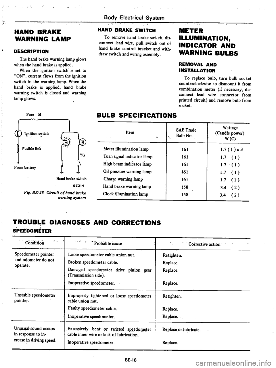
DESCRIPTION
The
hand
brake
warning
lamp
glows
when
the
hand
brake
is
applied
When
the
ignition
switch
is
set
to
ON
current
flows
from
the
ignition
switch
to
the
warning
lamp
When
the
hand
brake
is
applied
hand
brake
warning
switch
is
closed
and
warning
lamp
glows
Fuse
M
Ignition
5
tch
Fusible
link
From
battery
I
YG
1
1
Hand
brake
sWitch
BE314
Fig
BE
28
Circuit
of
hand
broke
warning
Iystem
Body
Electrical
System
HAND
BRAKE
SWITCH
To
remove
hand
brake
switch
dis
connect
lead
wire
pull
switch
out
of
hand
brake
control
bracket
and
with
draw
switch
and
wiring
assembly
METER
ILLUMINATION
INDICATOR
AND
WARNING
BULBS
REMOVAL
AND
INSTALLATION
To
replace
bulb
turn
bulb
socket
counterclockwise
to
dismount
it
from
combination
meter
if
necessary
dis
connect
lead
wire
connector
from
printed
circuit
and
remove
bulb
from
socket
BULB
SPECIFICATIONS
Item
Meter
illumination
lamp
Turn
signal
indicator
lamp
High
beam
indicator
lamp
Oil
pressure
warning
lamp
Charge
warning
lamp
Hand
brake
warning
lamp
Clock
illumination
lamp
SAE
Trade
Bulb
No
Wattage
Candle
power
W
e
161
161
161
161
161
158
158
1
7
I
x3
1
7
I
1
7
I
I
7
I
1
7
I
3
4
2
3
4
2
TROUB
E
DIAGNOSES
AND
CORRECTIONS
SPEEDOMETER
Condition
Speedometer
pointer
and
odometer
do
not
operate
Unstable
speedometer
pointer
Unusual
sound
occurs
in
response
to
in
crease
in
driving
speed
Probable
cause
Loose
speedometer
cable
union
nut
Broken
speedometer
cable
Damaged
speedometer
drive
pinion
gear
Transmission
side
Inoperative
speedometer
Improperly
tightened
or
loose
speedometer
cable
union
nut
Faulty
speedometer
cable
Inoperative
speedometer
ExceS
jvelybent
or
twisted
speedOmeter
cable
inner
wire
or
lack
of
lubrication
Inoperative
speedometer
8El8
Coirective
action
Retighten
Replace
Replace
Replace
Retighten
Replace
Replace
Replace
or
lubricate
Replace