turn signal DATSUN PICK-UP 1977 Service Manual
[x] Cancel search | Manufacturer: DATSUN, Model Year: 1977, Model line: PICK-UP, Model: DATSUN PICK-UP 1977Pages: 537, PDF Size: 35.48 MB
Page 107 of 537
3
Check
diaphragm
for
small
holes
carcks
or
wear
4
Check
rocker
arm
for
wear
at
the
mating
portion
with
camshaft
5
Check
rocker
arm
pin
for
wear
A
worn
pin
may
cause
oil
leakage
6
Check
all
other
components
for
any
abnormalities
and
replace
if
neces
sary
DESCRIPTION
INSPECTION
REMOVAL
AND
INSTALLATION
DESCRIPTION
The
electric
fuel
pump
is
adopted
on
air
conditioner
equipped
models
Engine
Fuel
ASSEMBLY
Reverse
the
order
of
disassembly
Closely
observe
the
following
instruc
tions
L
Use
new
gaskets
2
Lubricate
rocker
ann
rocker
arm
link
and
rocker
arm
pin
before
installa
tion
3
To
test
the
function
proceed
as
follows
Position
fuel
pump
assembly
about
I
meter
3
3
ft
above
fuel
level
of
fuel
strainer
and
connect
a
pipe
from
strainer
to
fuel
pump
Operate
rocker
arm
by
hand
If
fuel
is
drawn
up
soon
after
rocker
arm
is
released
fuel
pump
is
functioning
properly
ELECTRIC
FUEL
PUMP
CONTENTS
EF
11
EF
11
EF
12
DISASSEMBL
Y
ASSEMBL
Y
TROUBLE
DIAGNOSES
AND
CORRECTIONS
EF
12
EF
12
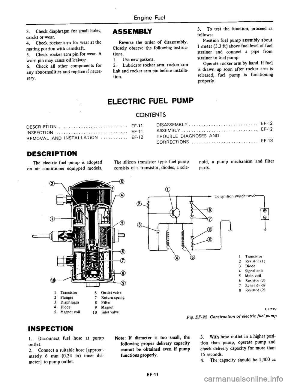
The
silicon
transistor
type
fuel
pump
consists
of
a
transistor
diodes
a
sole
I
Tr
lOsistor
6
Ou
tIet
valve
2
Plunger
7
Return
spring
3
Diaphragm
8
Filter
4
Diode
9
Magnet
5
Magnet
coil
10
Inlet
valve
INSPECTION
I
Disconnect
fuel
hose
at
pump
outlet
2
Connect
a
suitable
hose
approxi
mately
6
mm
0
24
in
inner
dia
meter
to
pump
outlet
ev
J
J
Note
If
diameter
is
too
small
the
following
proper
delivery
capacity
cannot
be
obtained
even
if
pump
functions
properly
EF
11
EF
13
noid
a
pump
mechanism
and
filter
parts
I
T
nsistor
2
Re
ist
f
I
3
Dinde
4
Signal
coil
5
Main
coil
6
Resistor
3
7
Zener
dlOdl
8
Resistor
2
EF719
Fig
EF
22
Construction
of
electric
fuel
pump
3
With
hose
outlet
in
a
higher
posi
tion
than
pump
operate
pump
and
check
delivery
capacity
for
more
than
15
seconds
4
The
capacity
should
be
I
400
cc
Page 114 of 537
FLOAT
SYSTEM
There
IS
only
one
float
chamber
while
two
l
arburetor
systems
primary
Jnd
st
l
ondary
are
provided
Fuel
fed
from
the
fuel
pump
flows
through
the
filler
and
needle
valve
into
the
flo
t
chamber
A
constant
fuel
level
is
maintained
by
the
float
and
needle
valve
Because
of
the
inner
air
vent
type
of
the
float
chamber
ventilation
the
fuel
consumption
will
not
be
in
fluenced
by
some
dirt
accumulated
in
the
air
deaner
The
needle
valve
includes
special
hard
steel
ball
and
will
not
wear
for
all
its
considerably
long
use
Besides
the
inserrion
of
a
spring
wiU
prevent
the
flooding
at
rough
road
running
BOOST
CONTROLLED
DECELERATION
DEVICE
B
C
D
D
A
Boost
Controlled
Deceleration
Device
B
C
D
D
serves
to
reduce
the
hydrocarbons
He
emitted
from
en
gine
during
coasting
The
high
manifold
vacuum
during
coasting
prevents
the
mixture
from
complete
combustion
because
of
the
reduced
amount
of
mixture
per
cyl
inder
per
rotation
of
engine
with
the
result
that
a
large
amount
of
hydrocar
bons
is
emitted
into
tile
atmosphere
The
B
C
D
D
has
been
designed
to
correct
this
problem
It
opern
tes
as
follows
when
the
manifold
vacuum
exceeds
a
pre
Engine
Fuel
determined
value
the
B
C
D
D
intro
duces
an
additional
mixture
of
opti
mum
mixture
ratio
and
quantity
into
the
manifold
by
opening
a
separate
mixture
passage
in
the
carburetor
Complete
combustion
of
fuel
is
assist
ed
by
this
additional
mixture
and
the
amount
of
H
C
contained
in
exhaust
gases
is
dramatically
reduced
During
the
transition
period
from
coasting
to
idling
the
transmission
produces
a
signal
which
turns
on
the
vacuum
control
solenoid
valve
As
this
takes
place
the
valve
is
lifted
off
its
seat
opening
the
vacuum
chamber
to
the
atmosphere
The
mixture
control
valve
is
then
closed
returning
the
engine
to
the
predetermined
idling
speed
On
manual
transmission
models
this
system
consists
of
B
C
D
D
vacuo
urn
control
solenoid
valve
speed
de
tecting
switch
and
amplifier
On
automatic
transmission
models
it
consists
of
B
C
D
D
vacuum
con
trol
solenoid
valve
and
inhibitor
switch
B
C
D
D
operation
Diaphragm
I
Qj
monitors
the
mani
fold
vacuum
and
when
the
vacuum
exceeds
a
pre
fetermined
value
acts
so
as
to
open
the
vacuum
control
valve
@
This
causes
the
manifold
vacu
urn
to
be
introduced
into
the
second
vacuum
chamber
and
actuates
dia
phragm
ll@
When
diaphrngm
II
operates
the
mixture
control
valve
@
opens
the
passage
and
introduces
the
additional
mixture
into
the
manifold
EF
18
The
amount
of
the
mixture
is
con
trolled
by
the
servo
action
of
the
mixture
control
valve
CID
and
vacuum
control
valve
@
so
that
the
manifold
vacuum
may
be
kept
at
the
pre
determined
value
The
amount
of
mixture
depends
mainly
upon
the
coasting
air
bleed
II@
while
the
mixture
ratio
is
deter
mined
by
the
coasting
jet
@
and
coasting
air
bleed
@
See
Figure
EF
31
Vacuum
control
solenoid
valve
operation
Manual
transmission
models
The
vacuum
control
solenoid
valve
is
con
troDed
by
a
speed
detecting
switch
that
is
actuated
by
the
speed
ometer
needle
As
the
vehicle
speed
falls
below
10
MPH
this
switch
is
activated
pro
ducing
a
signal
This
signal
actuates
the
amplifier
to
open
the
vacuum
control
solenoid
valve
Automatic
transmission
models
When
the
shift
lever
is
in
N
or
P
position
the
inhibitor
switch
mounted
on
the
transmission
turns
on
to
open
the
vacuum
control
solenoid
valve
Page 195 of 537
Primary
winding
1
Ignition
coo
I
Secondary
winding
CALIFORNIA
MODELS
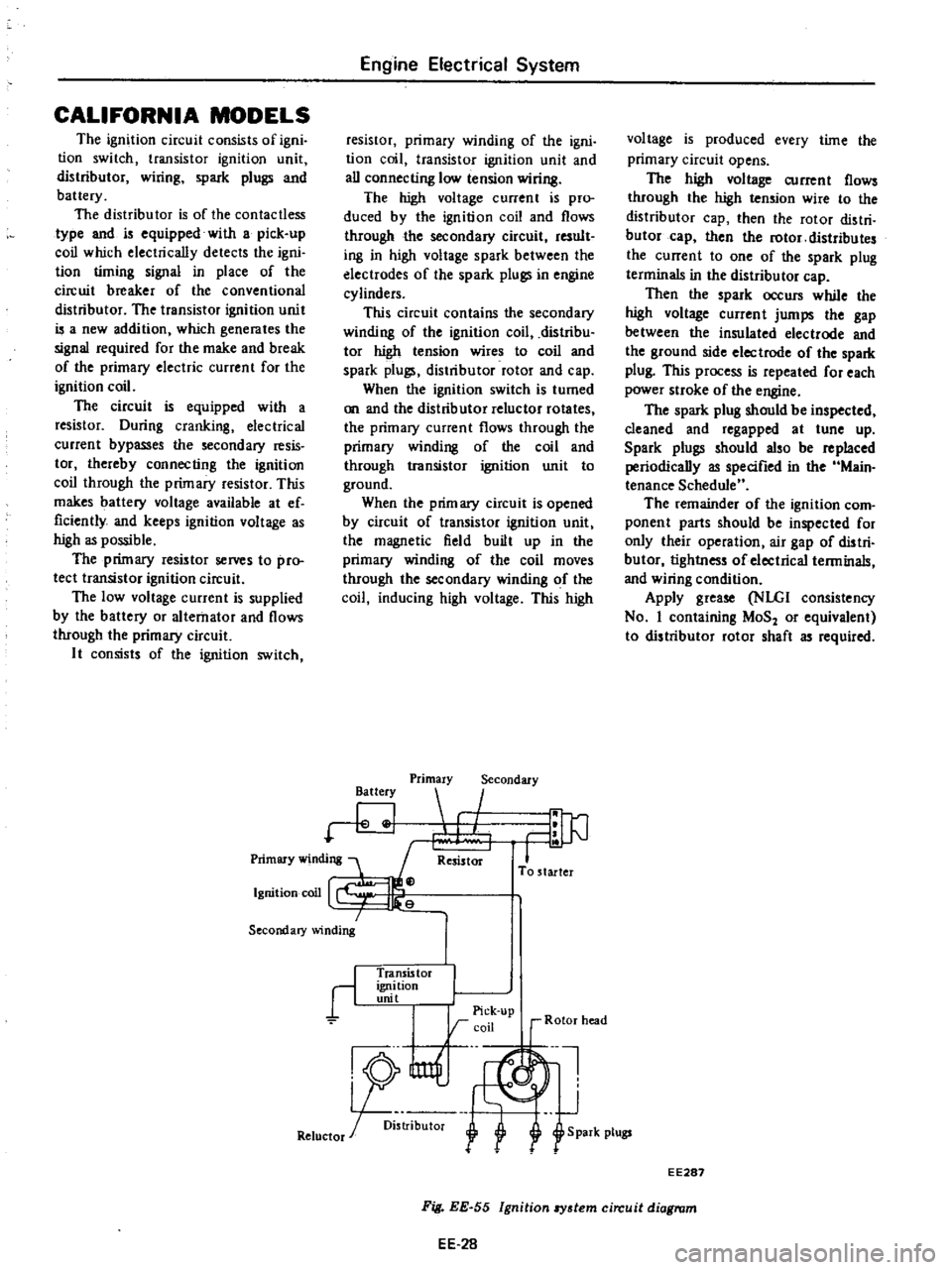
The
ignition
circuit
consists
of
igni
tion
switch
transistor
ignition
unit
distributor
wiring
spark
plugs
and
battery
The
distributor
is
of
the
contactless
type
and
is
equipped
with
a
pick
up
coil
which
electrically
detects
the
igni
tion
timing
signal
in
place
of
the
circuit
breaker
of
the
conventional
distributor
The
transistor
ignition
unit
is
a
new
addition
which
generates
the
signal
required
for
the
make
and
break
of
the
primary
electric
current
for
the
ignition
coil
The
circuit
is
equipped
with
a
resistor
During
cranking
electrical
current
bypasses
the
secondary
resis
tor
thereby
connecting
the
ignition
coil
through
the
primary
resistor
This
makes
battery
voltage
available
at
ef
ficiently
and
keeps
ignition
voltage
as
high
as
possible
The
primary
resistor
selVeS
to
pro
tect
transistor
ignition
circuit
The
low
voltage
current
is
supplied
by
the
battery
or
alternator
and
flows
through
the
primary
circuit
It
consists
of
the
ignition
switch
Engine
Electrical
System
resistor
primary
winding
of
the
igni
tion
coil
transistor
ignition
unit
and
all
connecting
low
tension
wiring
The
high
voltage
current
is
pro
duced
by
the
ignition
coil
and
flows
through
the
secondary
circuit
result
ing
in
high
voltage
spark
between
the
electrodes
of
the
spark
plugs
in
engine
cylinders
This
circuit
contains
the
secondary
winding
of
the
ignition
coil
distribu
tor
high
tension
wires
to
coil
and
spark
plugs
distributor
rotor
and
cap
When
the
ignition
switch
is
turned
on
and
the
distributor
reluctor
rotates
the
primary
current
flows
through
the
primary
winding
of
the
coil
and
through
transistor
ignition
unit
to
ground
When
the
prim
ary
circuit
is
opened
by
circuit
of
transistor
ignition
unit
the
magnetic
field
built
up
in
the
primary
winding
of
the
coil
moves
through
the
secondary
winding
of
the
coil
inducing
high
voltage
This
high
Battery
Primary
Secondary
I
Resistor
To
starter
r
Transis
tor
ignition
unit
I
I
Pick
up
rcoil
r
Rotor
head
nl
J
R5
U1f
1
Retuctor
r
oi
l
f
S
park
plugs
voltage
is
produced
every
time
the
primary
circuit
opens
The
high
voltage
current
flows
through
the
high
tension
wire
to
the
distributor
cap
then
the
rotor
distri
butor
cap
then
the
rotor
distributes
the
current
to
one
of
the
spark
plug
terminals
in
the
distributor
cap
Then
the
spark
occurs
while
the
high
voltage
current
jumps
the
gap
between
the
insulated
electrode
and
the
ground
side
electrode
of
the
spark
plug
This
process
is
repeated
for
each
power
stroke
of
the
engine
The
spark
plug
should
be
inspected
cleaned
and
regapped
at
tune
up
Spark
plugs
should
also
be
replaced
periodically
as
specified
in
the
Main
tenance
Schedule
The
remainder
of
the
ignition
com
ponent
parts
should
be
inspected
for
only
their
operation
air
gap
of
distri
butor
tightness
of
electrical
terminals
and
wiring
condition
Apply
grease
NLGI
consistency
No
I
containing
MoS
or
equivalent
to
distributor
rotor
shaft
as
required
EE287
EE
28
Fig
EE
55
Ignition
8Y3tem
circuit
diagram
Page 200 of 537
Engine
Electrical
System
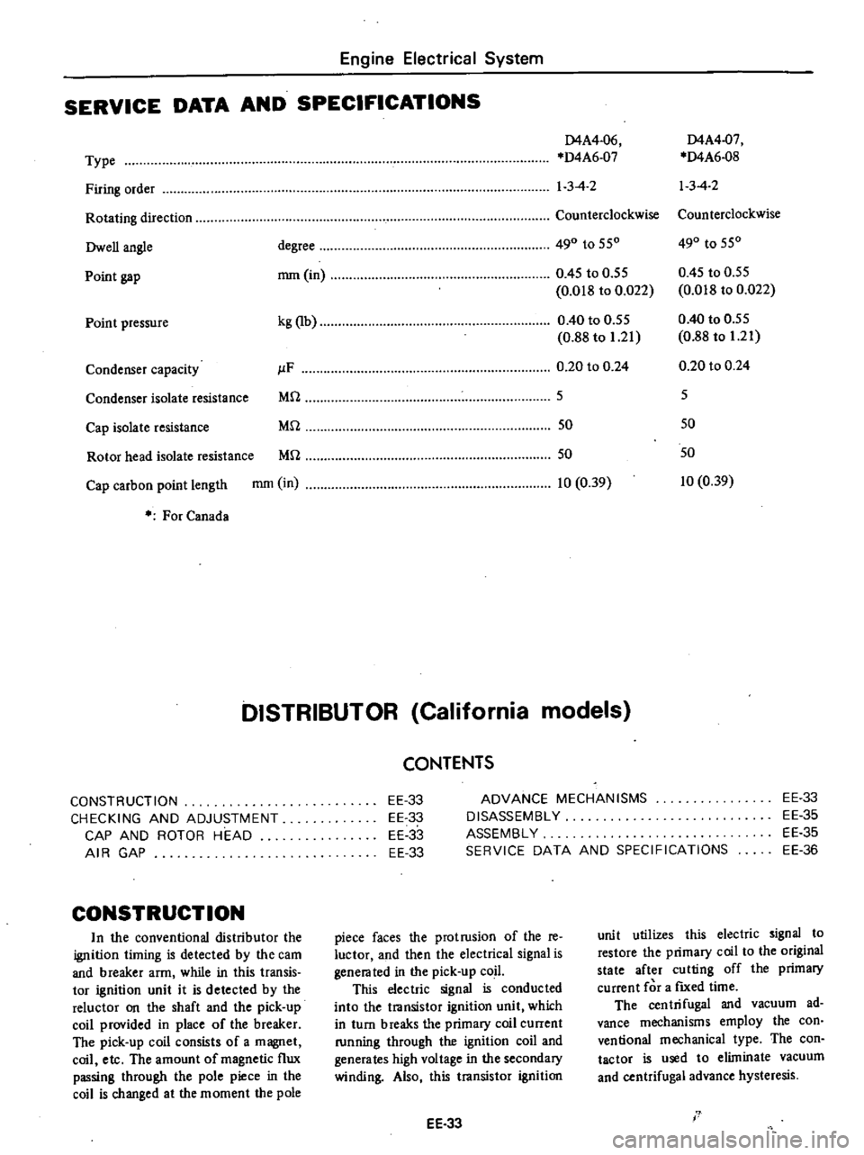
SERVICE
DATA
AND
SPECIFICATIONS
D4A4
06
D4A4
07
Type
D4A6
07
D4A6
08
Firing
order
1
3
4
2
13
4
2
Rotating
direction
Counterclockwise
Counterclockwise
Owen
angle
degree
490
to
550
490
to
550
Point
gap
mm
in
0
45
to
0
55
0
45
to
0
55
0
018
to
0
022
0
018
to
0
022
Point
pressure
kg
lb
0
40
to
0
55
0
40
to
0
55
0
88
to
1
21
0
88
to
1
21
Condenser
capacity
JlF
0
20
to
0
24
0
20
to
0
24
Condenser
isolate
resistance
Mrl
5
5
Cap
isolate
resistance
Mrl
50
50
Rotor
head
isolate
resistance
Mrl
50
50
Cap
carbon
point
length
mm
in
10
0
39
10
0
39
For
Canada
DISTRIBUTOR
California
models
CONSTRUCTION
CHECKING
AND
ADJUSTMENT
CAP
AND
ROTOR
HEAD
AIR
GAP
CONSTRUCTION
In
the
conventional
distributor
the
ignition
liming
is
detected
by
the
cam
and
breaker
arm
while
in
this
transis
tor
ignition
unit
it
is
detected
by
the
reluctor
on
the
shaft
and
the
pick
up
coil
provided
in
place
of
the
breaker
The
pick
up
coil
consists
of
a
magnet
coil
etc
The
amount
of
magnetic
flux
passing
through
the
pole
piece
in
the
coil
is
changed
at
the
moment
the
pole
CONTENTS
EE
33
EE
33
EE
33
EE
33
ADVANCE
MECHANISMS
DISASSEMBLY
ASSEMBLY
SERVICE
DATA
AND
SPECIFICATIONS
EE
33
EE
35
EE
35
EE
36
piece
faces
the
protrusion
of
the
re
luctor
and
then
the
electrical
signal
is
genera
ted
in
the
pick
up
coil
This
electric
signal
is
conducted
into
the
transistor
ignition
unit
which
in
turn
breaks
tI
e
primary
coil
current
running
through
the
ignition
coil
and
generates
high
voltage
in
the
secondary
winding
Also
this
transistor
ignition
EE
33
unit
utilizes
this
electric
signal
to
restore
the
primary
coil
to
the
original
state
after
cutting
off
the
primary
current
for
a
fIXed
time
The
centrifugal
and
vacuum
ad
vance
mechanisms
employ
the
con
ventional
mechanical
type
The
con
tactor
is
used
to
eliminate
vacuum
and
centrifugal
advance
hysteresis
I
Page 203 of 537
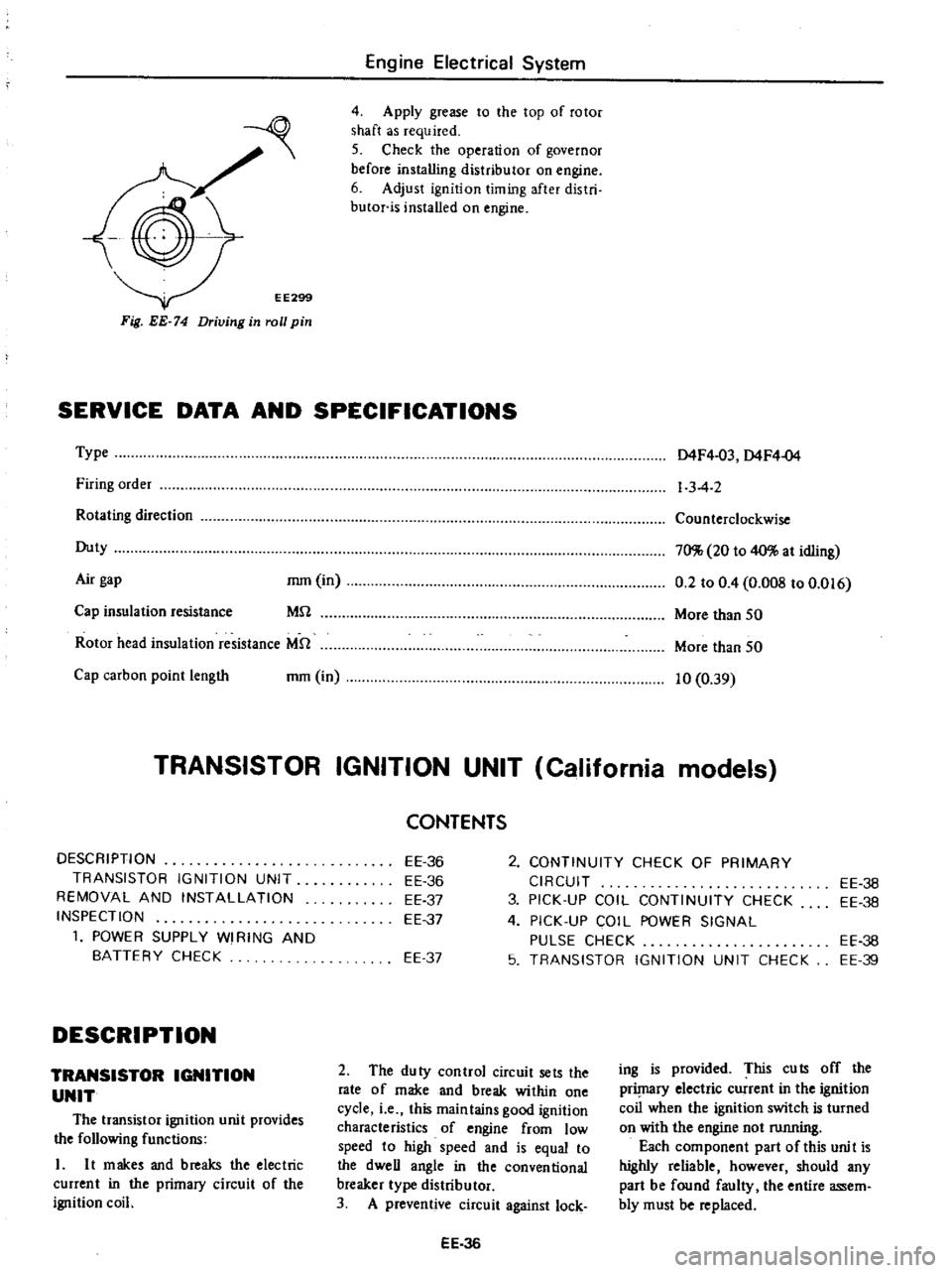
EE299
Fig
EE
74
Driving
in
roll
pin
Engine
Electrical
System
4
Apply
grease
to
the
top
of
rotor
shaft
as
required
5
Check
the
operation
of
governor
before
installing
distributor
on
engine
6
Adjust
ignition
timing
after
distri
butor
is
installed
on
engine
SERVICE
DATA
AND
SPECIFICATIONS
Type
Firing
order
Rotating
direction
Duty
Air
gap
mm
in
MU
Cap
insulation
resistance
Rotor
head
insulation
resistance
MU
Cap
carbon
point
length
mm
in
D4F4
03
D4F4
04
1
3
4
2
Counterclockwise
70
20
to
40
at
idling
0
2
to
0
4
O
OOS
to
0
016
More
than
50
More
than
50
10
0
39
TRANSISTOR
IGNITION
UNIT
California
models
DESCRIPTION
TRANSISTOR
IGNITION
UNIT
REMOVAL
AND
INSTALLATION
INSPECTION
1
POWER
SUPPLY
WI
RING
AND
BATTERY
CHECK
DESCRIPTION
TRANSISTOR
IGNITION
UNIT
The
transistor
ignition
unit
provides
the
following
functions
L
It
makes
and
breaks
the
electric
current
in
the
primacy
circuit
of
the
ignition
coil
2
CONTINUITY
CHECK
OF
PRIMARY
CIRCUIT
3
PICK
UP
COIL
CONTINUITY
CHECK
4
PICK
UP
COIL
POWER
SIGNAL
PULSE
CHECK
5
TRANSISTOR
IGNITION
UNIT
CHECK
CONTENTS
EE
36
EE
36
EE
37
EE
37
EE
37
2
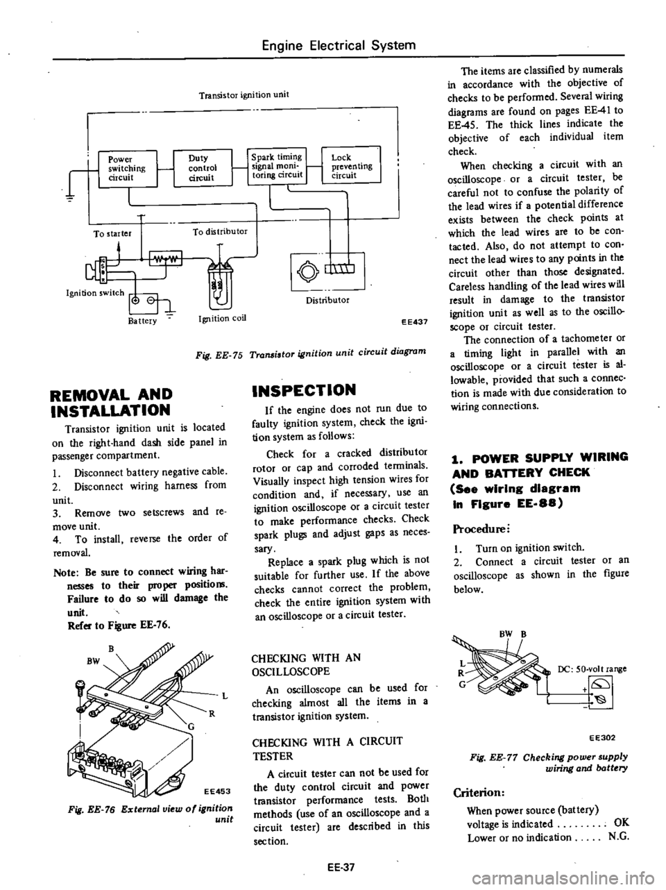
The
duty
control
circuit
sets
the
rate
of
make
and
break
within
one
cycle
i
e
this
maintains
good
ignition
characteristics
of
engine
from
low
speed
to
high
speed
and
is
equal
to
the
dweU
angle
in
the
conventional
breaker
type
distributor
3
A
preventive
circuit
against
lock
EE
36
EE
36
EE
38
EE
38
EE
39
ing
is
provided
This
cuts
off
the
prilnaCY
electric
current
in
the
ignition
coil
when
the
ignition
switch
is
turned
on
with
the
engine
not
running
Each
component
part
of
this
unit
is
highly
reliable
however
should
any
part
be
found
faulty
the
entire
assem
bly
must
be
replaced
Page 204 of 537
Engine
Electrical
System
Transistor
ignition
unit
r
1
Power
switching
circuit
Duty
control
circuit
To
starter
To
distributor
Ba
ttery
Ignition
coil
1
Spark
timing
1
Signal
mom
toring
circuit
Lock
j
preven
ling
circuit
nm
Distributor
EE437
Fig
EE
75
Transistor
ignition
unit
circuit
diagram
REMOVAL
AND
INSTALLATION
Transistor
ignition
unit
is
located
on
the
right
hand
dash
side
panel
in
passenger
compartment
Disconnect
battery
negative
cable
2
Disconnect
wiring
harness
from
unit
3
Remove
two
setscrews
and
te
move
unit
4
To
install
reverse
the
order
of
removal
Note
Be
sure
to
connect
wiring
har
nesses
to
their
proper
positio
Failure
to
do
so
will
damage
the
unit
Refer
to
Figure
EE
76
Fig
EE
76
External
view
of
ignition
unit
INSPECTION
If
the
engine
does
not
run
due
to
faulty
ignition
system
check
the
igni
tion
system
as
follows
Check
for
a
cracked
distributor
rotor
or
cap
and
corroded
tenninals
Visually
inspect
high
tension
wires
for
condition
and
if
necessary
use
an
ignition
oscilloscope
or
a
circuit
tester
to
make
performance
checks
Check
spark
plugs
and
adjust
gaps
as
neces
sary
Replace
a
spark
plug
which
is
not
suitable
for
further
use
If
the
above
checks
cannot
correct
the
problem
check
the
entire
ignition
system
with
an
oscilloscope
or
a
circuit
tester
L
CHECKING
WITH
AN
OSCILLOSCOPE
An
oscilloscope
can
be
used
for
checking
almost
all
the
items
in
a
transistor
ignition
system
CHECKING
WITH
A
CIRCUIT
TESTER
A
circuit
tester
can
not
be
used
for
the
duty
control
circuit
and
power
t18nsistor
performance
tests
Both
methods
use
of
an
oscilloscope
and
a
circuit
tester
are
described
in
this
section
EE
37
The
items
are
classified
by
numerals
in
accordance
with
the
objective
of
checks
to
be
performed
Several
wiring
diagrams
are
found
on
pages
EE
41
to
EE
45
The
thick
lines
indicate
the
objective
of
each
individual
item
check
When
checking
a
circuit
with
an
oscilloscope
or
a
circuit
tester
be
careful
not
to
confuse
the
polarity
of
the
lead
wires
if
potential
difference
exists
between
the
check
points
at
which
the
lead
wires
are
to
be
con
tacted
Also
do
not
attempt
to
con
nect
the
lead
wires
to
any
points
in
the
circuit
other
than
those
designated
Careless
handling
of
the
lead
wires
will
result
in
damage
to
the
transistor
ignition
unit
as
well
as
to
the
oscillo
scope
or
circuit
tester
The
connection
of
a
tachometer
or
a
timing
light
in
parallel
with
an
oscilloscope
or
a
circuit
tester
is
al
lowable
provided
that
such
a
connec
tion
is
made
with
due
consideration
to
wiring
connections
1
POWER
SUPPLY
WIRING
AND
BAnERY
CHECK
See
wIrIng
diagram
In
FIgure
EE
88
Procedure
I
Turn
on
ignition
switch
2
Connect
a
circuit
tester
or
an
oscilloscope
as
shown
in
the
figure
below
DC
50
volt
range
EE302
Fig
EE
77
Checking
power
supply
wiring
and
batt
ry
Criterion
When
power
source
battery
voltage
is
indicated
OK
Lower
or
no
indication
N
G
Page 205 of 537
If
the
result
is
N
C
Take
the
following
measures
I
Check
BW
and
B
color
wire
harness
respectively
for
proper
con
ductance
2
Check
battery
terminals
for
proper
connection
3
Check
charge
condition
of
bat
tery
if
an
excessively
low
voltage
is
indicated
2
CONTINUITY
CHECK
OF
PRIMARY
CIRCUIT
2
1
CheckIng
prImary
circuit
See
wiring
diagram
In
Fig
EE
89
Proced
ure
I
Disconnect
L
color
wire
from
ignition
unit
2
Turn
on
ignition
switch
3
C
ooneet
a
cireui
t
tester
or
an
oscilloscope
as
shown
in
Figure
EE
78
DC
50
volt
range
tf
S
EE303
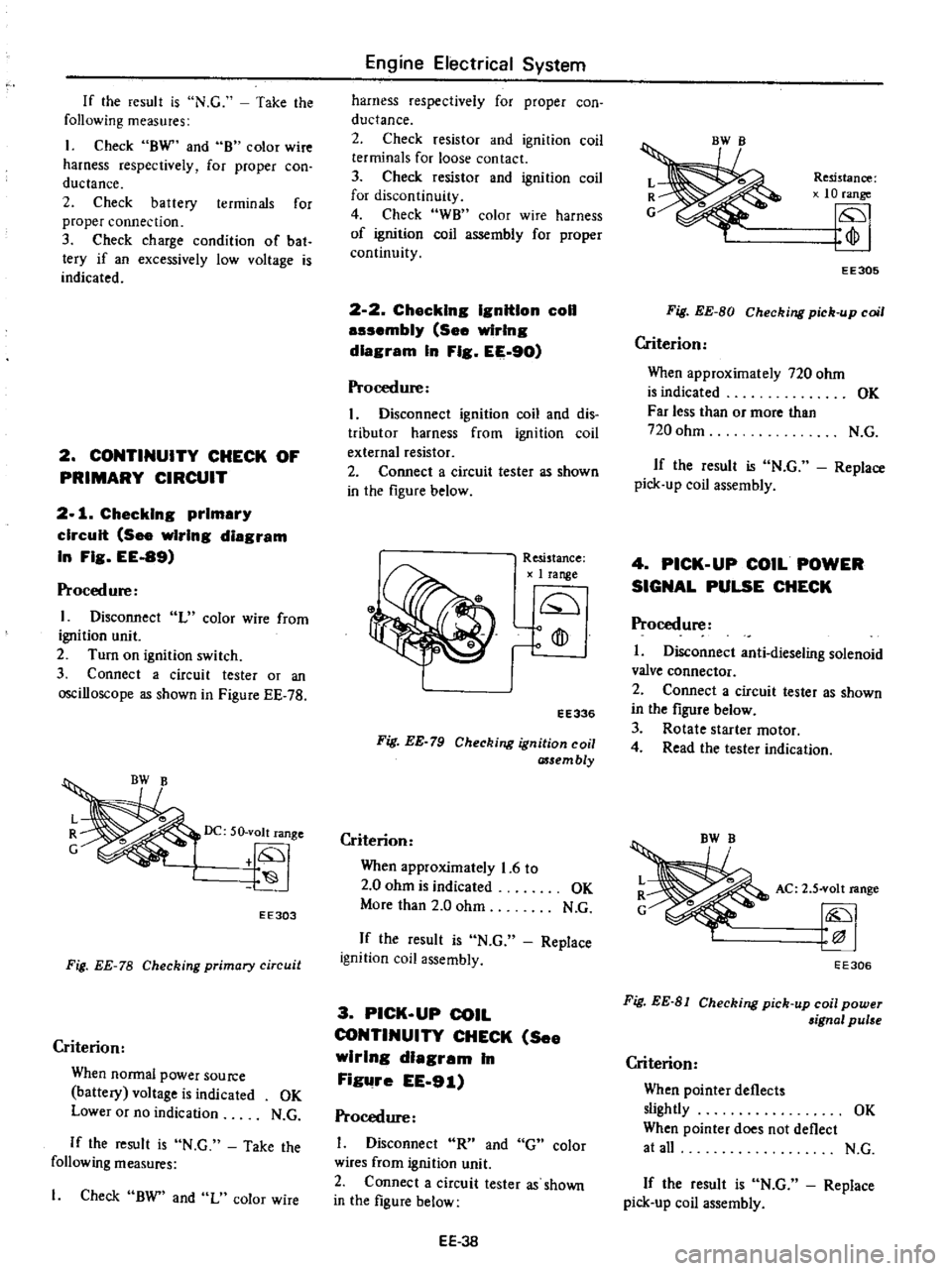
Fig
EE
78
Checking
primary
circuit
Criterion
When
Donnal
power
Source
battery
voltage
is
indicated
OK
Lower
or
no
indication
N
G
If
the
result
is
N
C
Take
the
following
measures
1
Check
BW
and
L
color
wire
Engine
Electrical
System
harness
respectively
for
proper
con
ductance
2
Check
resistor
and
ignition
coil
terminals
for
loose
contact
3
Check
resistor
and
ignition
coil
for
discontinuity
4
Check
WB
color
wire
harness
of
ignition
coil
assembly
for
proper
continuity
2
2
Chacklng
IgnitIon
coil
auembly
See
wiring
diagram
In
Fig
EE
90
Procedure
I
Disconnect
ignition
coil
and
dis
tributor
harness
from
ignition
coil
external
resistor
2
Connect
a
circuit
tester
as
shown
in
the
figure
below
Resistance
1
range
Q
o
fD
ro
EE336
Fig
EE
79
Checking
ignition
coil
assembly
Criterion
When
approximately
1
6
to
2
0
ohm
is
indicated
OK
More
than
2
0
ohm
N
C
If
the
result
is
N
C
Replace
ignition
coil
assembly
3
PICK
UP
COIL
CONTINUITY
CHECK
See
wirIng
dIagram
In
Figure
EE
91
Procedure
Disconnect
R
and
G
color
wires
from
ignition
unit
2
Connect
a
circuit
tester
as
shown
in
the
figure
below
EE
3B
Resistance
10
range
fp
EE305
Fig
EE
BO
Checking
pick
up
coil
Criterion
When
approximately
720
ohm
is
indicated
OK
Far
less
than
or
more
than
720
ohm
N
C
If
the
result
is
N
C
Replace
pick
up
coil
assembly
4
PICK
UP
COIL
POWER
SIGNAL
PULSE
CHECK
Procedure
I
Disconnect
anti
dieseling
solenoid
valve
connector
2
Connect
a
circuit
tester
as
shown
in
the
figure
below
3
Rotate
starter
motor
4
Read
the
tester
indication
AC
2
S
volt
range
EE306
Fig
EE
81
Checking
pick
up
coil
power
aignal
pulse
Criterion
When
pointer
deflects
slightly
OK
When
pointer
does
not
deflect
at
all
N
C
If
the
result
is
N
C
Replace
pick
up
coil
assembly
Page 364 of 537
Condition
Vehicle
puBes
to
right
or
left
Instability
of
vehicle
Stiff
steeirng
wheel
Excessive
steering
wheel
play
Noise
Front
Axle
Front
Suspension
Probable
cause
Deformed
of
steering
linkage
and
suspension
link
Unbalanced
vehicle
level
Improper
air
pressure
of
tire
Worn
or
loose
suspension
link
screw
bushing
Incorrect
wheel
alignment
Worn
or
deformed
steering
linkage
and
suspension
link
Incorrect
adjustment
of
steering
gear
Deformed
unbalanced
wheel
Check
and
correct
in
the
following
manner
Jack
up
front
wheels
detach
the
steering
gear
and
operate
the
steering
wheel
and
a
If
it
is
light
check
steering
linkage
and
suspension
groups
b
If
it
is
heavy
check
steering
gear
and
steering
column
groups
Improper
air
pressure
of
tire
Insufficient
lubricants
or
mixing
impurities
in
steering
linkage
or
excessively
worn
steering
linkage
Insufficient
lubricant
in
gear
box
or
contaminated
lubricant
Unsmooth
king
pin
damaged
part
Or
insufficient
lubrication
Worn
or
incorrectly
adjusted
wheel
bearing
Worn
damaged
steering
gear
and
bearing
Incorrectly
adjusted
steering
gear
Deformed
steering
linkage
Incorrect
wheel
alignment
Interference
of
steering
column
with
turn
signal
switch
Incorrectly
adjusted
steering
gear
Worn
steering
linkage
idler
arm
Improperly
fitted
of
gear
box
Incorrectly
adjusted
wheel
bearing
Worn
or
loose
suspension
link
screw
bushing
Improper
air
pressure
of
tire
Insufficient
lubricating
oil
and
grease
for
suspension
link
screw
bushing
and
steering
linkage
or
their
breakage
FA
15
Corrective
action
Replace
Correct
the
unbalance
Adjust
Replace
Adjust
Replace
Adjust
Correct
or
replace
Adjust
Replenish
grease
or
replace
the
part
Add
or
replace
gear
oil
Replace
Replace
or
adjust
Replace
Adjust
Replace
Adjust
Adjust
Adjust
Replace
Retighten
Adjust
Replace
Adjust
Replenish
lubricating
oil
and
grease
or
replace
Page 408 of 537
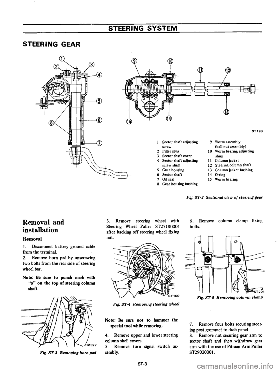
STEERING
GEAR
Removal
and
installation
Removal
I
Disconnect
battery
ground
cable
from
the
terminal
2
Remove
horn
pad
by
unscrewing
two
bolts
from
the
rear
side
of
steering
wheel
bar
Note
Be
sure
to
punch
mark
with
0
on
the
top
of
steering
column
shaft
Fig
ST
3
R
moving
horn
pad
STEERING
SYSTEM
A
@
@l
@
J
i
u
p
I
1
jj
ST199
Sector
shaft
adjusting
screw
2
Filler
plug
3
Sector
shaft
cover
4
Sector
shaft
adjusting
screw
shim
5
Gear
housing
6
Sector
shaft
7
Oil
l
8
Gear
housing
bushing
3
Remove
steering
wheel
with
Steering
Wheel
Puller
ST27I80001
after
backing
off
steering
wheel
fIXing
nut
Fig
ST
4
Removing
teering
wheel
Note
Be
sure
not
to
hammer
the
special
tool
while
removing
4
Remove
upper
and
lower
steering
column
shell
covers
S
Remove
turn
signal
switch
as
sembly
ST3
9
Worm
assembly
ball
nut
assembly
10
Worm
bearing
adjusting
shim
11
Column
jacket
12
Steering
column
shaft
13
Column
jacket
bushing
14
ring
15
Worm
bearing
Fig
ST
2
Sectional
view
of
steering
gear
6
Remove
column
clamp
fixing
bolts
c
@
I
f
c
I
1
I
1
i
T201
Fig
ST
5
Removing
column
clamp
7
Remove
four
bolts
securing
steer
ing
post
grommet
to
dash
panel
8
Remove
nut
securing
gear
arm
to
sector
shaft
and
then
withdraw
gear
arm
with
the
use
of
Pitman
Arm
Puller
ST2902000I
Page 431 of 537
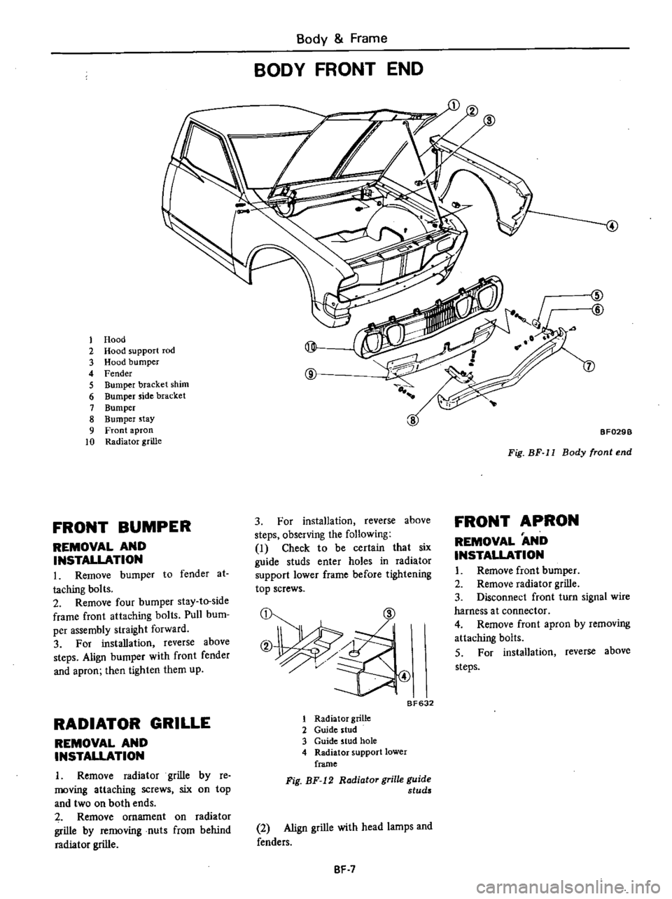
Body
Frame
BODY
FRONT
END
1
Hood
2
Hood
support
rod
@
3
Hood
bumper
4
Fender
@
5
Bumper
bracket
shim
6
Bumper
side
bracket
7
Bumper
8
Bumper
stay
9
Front
apron
10
Radiator
grille
FRONT
BUMPER
REMOVAL
AND
INSTALLATION
L
Remove
bumper
to
fender
at
taching
bolts
2
Remove
four
bumper
stay
to
side
frame
front
attaching
bolts
Pull
bum
per
assembly
straight
forward
3
For
installation
reverse
above
steps
Align
bumper
with
front
fender
and
apron
then
tighten
them
up
RADIATOR
GRILLE
REMOVAL
AND
INSTAUATION
I
Remove
radiator
grille
by
re
moving
attaching
screws
six
on
top
and
two
on
both
ends
Remove
ornament
on
radiator
grille
by
removing
nuts
from
behind
radiator
grille
4
ZID
@
7
BF029B
Fig
BF
11
Body
front
end
FRONT
APRON
3
For
installation
reverse
above
steps
observing
the
following
I
Check
to
be
certain
that
six
guide
studs
enter
holes
in
radiator
support
lower
frame
before
tightening
top
screws
CD
@
REMOVAL
AND
INSTALLATION
I
Remove
front
bumper
2
Remove
radiator
grille
3
Disconnect
front
turn
signal
wire
harness
a
t
connector
4
Remove
front
apron
by
removing
attaching
bolts
S
For
installation
reverse
above
steps
B
632
1
Radiator
grille
2
Guide
stud
3
Guide
stud
hole
4
Radiator
support
lower
frame
Fig
BF
12
Radiator
grille
guide
studs
2
Align
grille
with
head
lamps
and
fenders
BF
7