AUX DATSUN PICK-UP 1977 Service Manual
[x] Cancel search | Manufacturer: DATSUN, Model Year: 1977, Model line: PICK-UP, Model: DATSUN PICK-UP 1977Pages: 537, PDF Size: 35.48 MB
Page 266 of 537

the
space
from
I
to
IS
increases
space
from
15
to
the
drain
port
simultaneously
decreases
As
a
resull
governor
pressure
of
15
increases
and
the
governor
pressure
is
balanced
with
the
sum
of
centrifugal
force
and
spring
force
The
governor
pressure
thus
changes
in
response
to
the
vehicle
speed
change
centrifugal
force
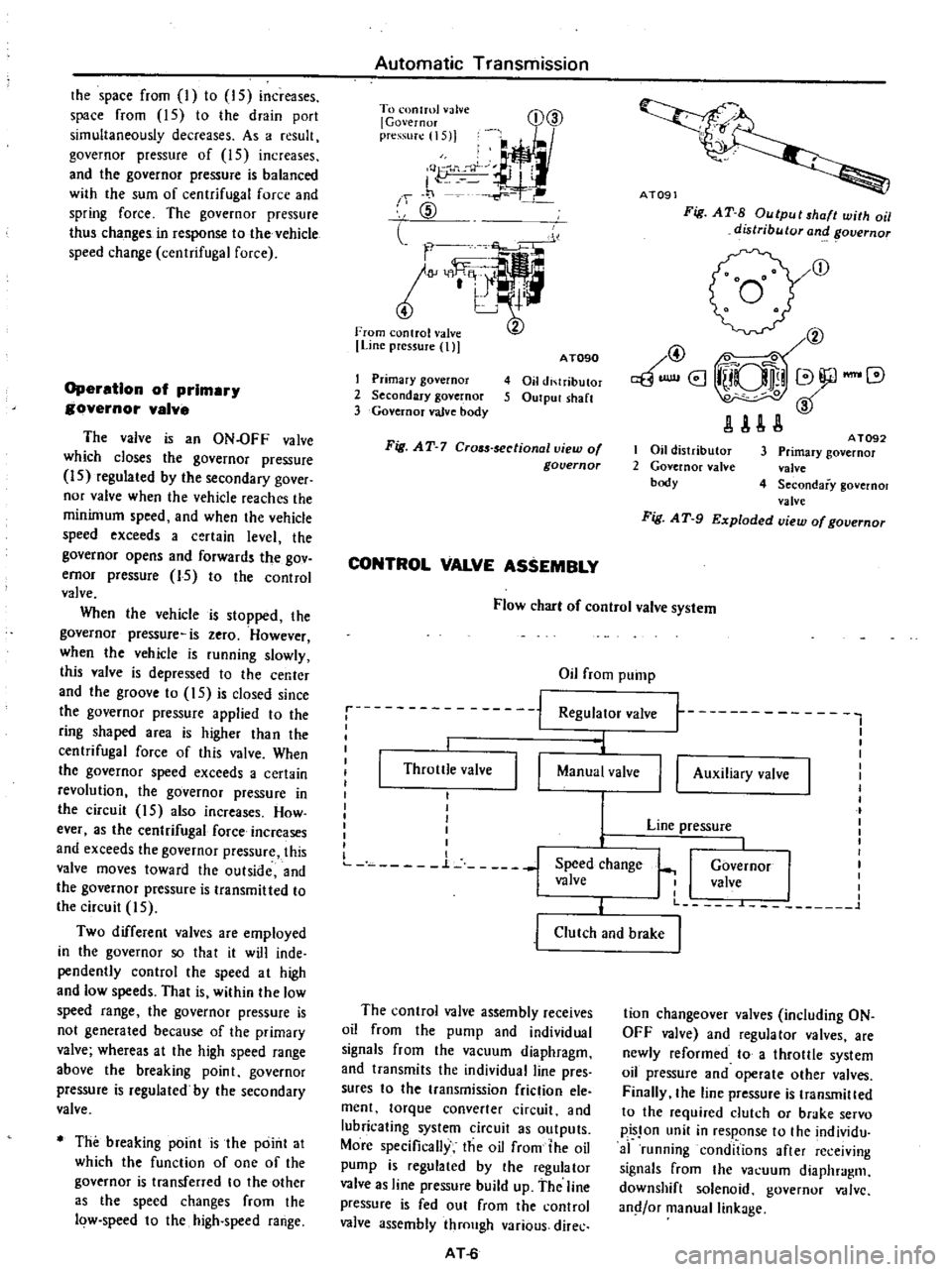
Operation
of
prlmar
governor
valve
The
valve
is
an
ON
OFF
valve
which
closes
the
governor
pressure
IS
regulated
by
the
secondary
gover
nor
valve
when
the
vehicle
reaches
the
minimum
speed
and
when
the
vehicle
speed
exceeds
a
certain
level
the
governor
opens
and
forwards
the
gov
ernor
pressure
15
to
the
control
valve
When
the
vehicle
is
stopped
the
governor
pressure
is
zero
However
when
the
vehicle
is
running
slowly
this
valve
is
depressed
to
Ihe
center
and
the
groove
to
15
is
closed
since
the
governor
pressure
applied
to
the
ring
shaped
area
is
higher
than
the
centrifugal
force
of
this
valve
When
the
governor
speed
exceeds
a
certain
revolution
the
governor
pressure
in
the
circuit
15
also
increases
How
ever
as
the
centrifugal
force
increases
and
exceeds
the
governor
pressure
this
valve
moves
toward
the
outside
and
the
governor
pressure
is
transmitted
to
the
circuil
5
Two
different
valves
are
employed
in
the
governor
so
that
it
will
inde
pendently
control
the
speed
at
high
and
low
speeds
That
is
within
the
low
speed
range
the
governor
pressure
is
not
generated
because
of
the
primary
valve
whereas
at
the
high
speed
range
above
the
breaking
point
governor
pressure
is
regulated
by
the
secondary
valve
The
breaking
point
is
the
point
at
which
the
function
of
one
of
the
governor
is
transferred
to
the
other
as
the
speed
changes
from
the
low
speed
to
the
high
speed
range
Automatic
Transmission
To
onlml
valve
l
Governor
pre
S1I
1I5
j
I
Q
J
J
f
1
1
CID
l
l
m
Line
pressure
t
D@
I
Primary
governor
2
Secondary
governor
3
Governor
valve
body
AT090
4
Oil
di
lributor
5
Output
sh
lft
Fig
AT
7
Cr05s
sectionallliew
of
governor
CONTROL
VALVE
ASSEMBLY
Ai09
Fig
AT
S
Output
shaft
with
oil
distributor
and
overnor
r
@
@
0
aBUlllI8
iUQlli
V
JlAU
I
Oil
distributor
2
Governor
nlve
body
A
T092
3
Primary
governor
valve
4
Secondary
governol
valve
Fig
A
T
9
Exploded
view
of
governor
Flow
cbar
of
control
valve
system
Oil
from
pump
Regulator
valve
1
I
i
j
Throttle
valve
I
I
l
Manual
valve
I
I
I
I
I
I
I
L
n
L
j
Speed
change
valve
I
I
t
t
I
I
I
I
I
I
Governor
I
I
valve
I
I
I
L
L
1
II
Auxiliary
valve
Line
pressure
j
Clutch
and
brake
The
control
valve
assembly
receives
oil
from
the
pump
and
individual
signals
from
the
vacuum
diaphragm
and
transmits
the
individual
line
pres
sures
to
the
transmission
friction
ele
ment
torque
converter
circuit
and
lubricating
system
circuit
as
outputs
More
specifically
the
oil
from
the
oil
pump
is
regulated
by
the
regulator
valve
as
line
pressure
build
up
the
line
pressure
is
fed
out
from
the
control
valve
assembly
through
various
direc
AT
6
tion
changeover
valves
including
ON
OFF
valve
and
regulator
valves
are
newly
reformed
to
a
throllle
system
oil
pressure
and
operate
other
valves
Finally
the
line
pressure
is
transmilled
to
the
required
dutch
or
brake
servo
pisJon
unit
in
response
to
the
individu
af
running
conditions
after
re
ejving
signals
from
the
va
uum
diaphragm
downshift
solenoid
governor
V
dlvc
and
or
manual
linkage
Page 273 of 537

HYDRAULIC
SYSTEM
AND
MECHANICAL
OPERATION
The
operating
system
of
oil
pres
sure
in
each
range
is
described
below
The
oil
pressure
in
each
circuit
shown
in
the
illustration
is
classified
as
follows
according
to
the
function
fhe
numeraJs
show
the
circuit
num
bers
Pressure
source
of
the
line
7
Operating
Iinc
prcssure
for
friction
elements
123456
8910
1112
Auxiliary
line
pressurc
13
Throttle
system
pressure
16
17
18
19
Others
14
15
Oil
pump
discharge
hole
7
Cd
Torque
converter
pressure
14
Rear
iutch
prc
surc
1
FTOOI
c1
tL
h
prc
ur
It
J
1
011
pump
Sllctlon
hole
M
IIJ1iIII
Automatic
Transmission
Fig
AT
21
Identification
of
oil
channels
in
oil
pump
AT105
Oil
pump
suction
hole
ATl06
Fig
AT
22
Identification
of
oil
channels
in
case
front
face
I
o
Oil
pump
dischar
hole
7
I9JM
c
Torque
converter
f
Os
I
1L
0
ervo
Ie
ease
pressure
14
0
pressure
10
Rear
clutch
Servo
t
ightening
ho
L
pressure
l
0
1
pressure
9
lJ
L
I
c
I
Front
clutch
IT
0
LIO
reverse
brake
pressure
12
U
r
FT
II
pressure
11
rrOil
pump
suction
hol
J
C
Jf
JC
O
Governor
pressure
15
Governor
feed
pressure
l
An07
Fig
AT
23
Identification
of
oil
channels
in
case
face
AT
13
Page 323 of 537

Automatic
Transmission
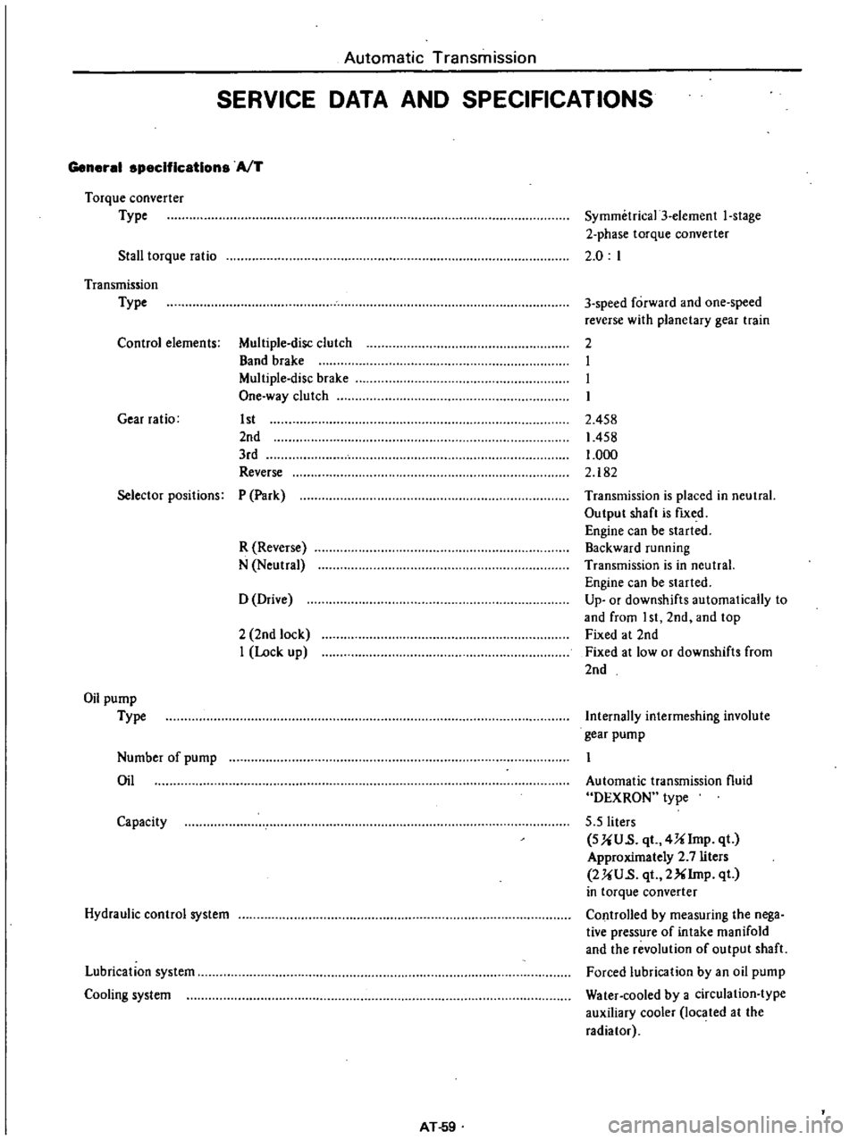
SERVICE
DATA
AND
SPECIFICATIONS
General
specifications
AfT
Torque
converter
Type
Stall
torque
ratio
Symmetrica13
element
I
stage
2
phase
torque
converter
2
0
I
Transmission
Type
Control
elements
Multiple
disc
clutch
Band
brake
Multiple
disc
brake
One
way
clutch
Gear
ratio
1st
2nd
3rd
Reverse
3
speed
forward
and
one
speed
reverse
with
planetary
gear
train
2
I
I
I
2
458
1458
1
000
2
182
Selector
positions
P
Park
R
Reverse
N
Neutral
Transmission
is
placed
in
neutral
Output
shaft
is
fIXed
Engine
can
be
started
Backward
running
Transmission
is
in
neutral
Engine
can
be
started
Up
or
downshifts
automatically
to
and
from
I
st
2nd
and
top
Fixed
at
2nd
Fixed
at
low
or
downshifts
from
2nd
o
Drive
2
2nd
lock
I
Lock
up
Oil
pump
Type
Internally
intermeshing
involute
gear
pump
Number
of
pump
Oil
Automatic
transmission
fluid
DEXRON
type
5
5
liters
SUU
s
qt
4Ulmp
qt
Approximately
2
7
liters
2UU
s
qt
2XIrnp
qt
in
torque
converter
Controlled
by
measuring
the
nega
tive
pressure
of
intake
manifold
and
the
revolution
of
output
shaft
Forced
lubrication
by
an
oil
pump
Water
cooled
by
a
circulation
type
auxiliary
cooler
located
at
the
radiator
Capacity
Hydraulic
control
system
Lubrication
system
Cooling
system
AT
59