wheel torque DATSUN PICK-UP 1977 Service Manual
[x] Cancel search | Manufacturer: DATSUN, Model Year: 1977, Model line: PICK-UP, Model: DATSUN PICK-UP 1977Pages: 537, PDF Size: 35.48 MB
Page 68 of 537
6
Make
sure
that
crankshaft
has
proper
end
play
Crankshaft
end
play
0
05
to
0
18
mm
0
0020
to
0
0071
in
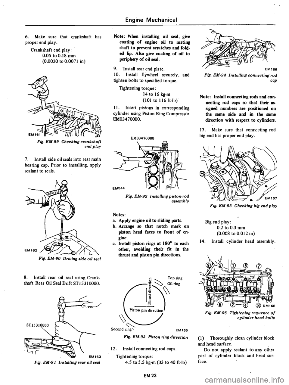
Fig
EM
89
Checking
crankshaft
end
play
7
Install
side
oil
seals
into
rear
main
bearing
cap
Prior
to
installing
apply
sealant
to
seals
Fig
EM
90
Driving
side
oil
seal
8
Install
rear
oil
seal
using
Crank
shaft
Rear
Oil
Seal
Drift
STI5310000
r
STl5310000
r
EM163
Fig
EM
91
Installing
rear
oi
seal
Engine
Mechanical
Note
When
installing
oil
seal
give
coating
of
engine
oil
to
mating
shaft
to
prevent
scratches
and
fold
ed
lip
Also
give
coating
of
oil
to
periphery
of
oil
seal
9
Install
rear
end
plate
10
Install
flywheel
securely
and
tighten
bolts
to
specified
torque
Tightening
torque
14
to
16
kg
m
101
to
116
ft
lb
I
I
Insert
pistons
in
corresponding
cylinder
using
Piston
Ring
Compressor
EM03470000
EM03410000
I
EM544
Fig
EM
92
Installing
pi8ton
rod
a
Sembly
Notes
a
Apply
engine
oil
to
sliding
parts
b
Arrange
80
that
notch
mark
on
piston
head
faces
to
front
of
en
gine
c
Install
piston
rings
at
1800
to
each
other
avoiding
their
fit
in
the
thrust
and
piston
pin
directions
6
Top
ring
I
iilring
Piston
pin
ireClioJ
EM165
Fig
EM
93
PUtan
ring
direction
12
Install
connecting
rod
caps
Tightening
torque
4
5
to
5
5
kg
m
33
to
40
ft
lb
EM
23
Fig
EM
94
Installing
connecting
rod
cap
Note
Install
connecting
rods
and
con
necting
rod
caps
80
that
their
as
signed
numbers
are
positioned
on
the
same
side
and
in
the
SlIme
direction
with
respect
to
cylinders
13
Make
sure
that
connecting
rod
big
end
has
proper
end
play
Fig
EM
95
Checking
big
end
play
Big
end
play
0
2
to
0
3
mm
0
008
to
0
Ql2
in
14
Install
cylinder
head
assembly
Fig
EM
96
Tightening
sequence
01
cylinder
head
bolts
J
Thoroughly
clean
cylinder
block
and
head
surface
Do
not
apply
sealant
to
any
other
part
of
cylinder
block
and
head
sur
face
Page 71 of 537
30
Install
heatshieid
plate
on
mani
fold
assembly
31
Install
air
gallery
pipe
on
ex
haust
manifold
32
Install
manifold
gasket
and
manifold
assembly
on
cylinder
head
Tightening
torque
1
2to
1
6kg
m
8
7
to
11
6
ft
lb
33
Install
blow
by
gas
pipe
on
cyl
inder
block
and
tighten
with
rear
engine
slinger
34
Install
thermostat
housing
gas
ket
thermostat
housing
and
thermo
stat
35
Install
thermal
vacuum
valve
on
thermostat
housing
Before
installing
apply
a
liquid
packing
slightly
to
the
threads
36
Install
FJ
C
D
bracket
on
cylin
der
head
37
Install
E
G
R
passage
and
E
G
R
valve
on
intake
manifold
38
Connect
E
G
R
tube
to
E
G
R
tube
and
exhaust
manifold
39
Install
check
valve
on
air
gallery
pipe
40
Install
air
cleaner
bracket
on
intake
manifold
41
Install
air
control
valve
on
air
cleaner
bracket
California
models
42
Install
vacuum
and
fuel
tubes
combined
on
cylinder
head
43
Install
distributor
assembly
44
Install
heatshield
plate
joint
seat
and
carburetor
Carbure10r
tightening
torque
0
5
to
1
0
kg
m
3
6
to
7
2
ft
lb
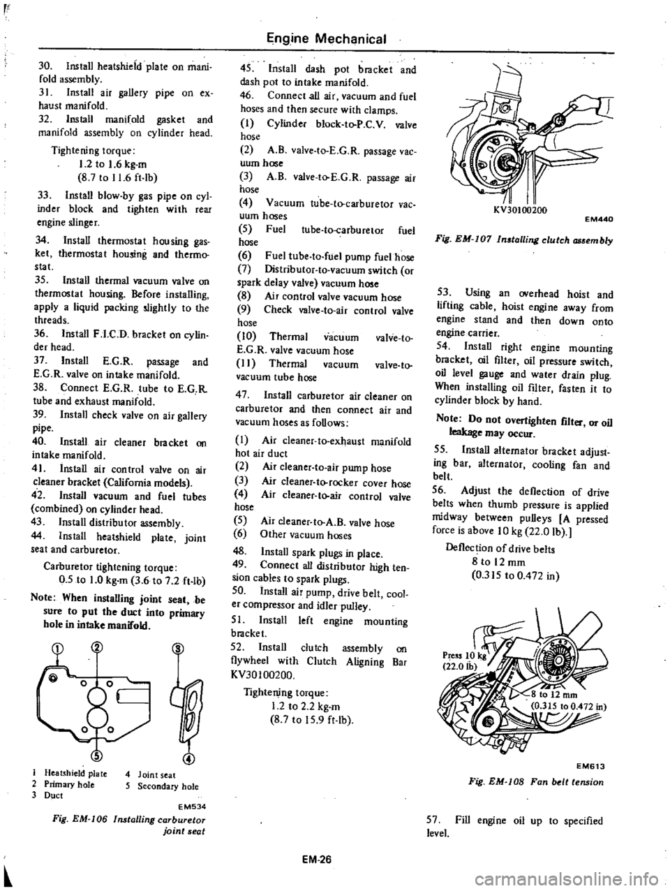
Note
When
instalUng
joint
seat
be
sure
to
put
the
duct
into
primary
hole
in
intake
manifold
S
J
Heatshield
plate
4
Joint
seat
2
Primary
hole
5
Secondary
hole
3
Duct
EM534
Fig
EM
I06
Installing
carburetor
joint
seat
Engine
Mechanical
45
Install
dash
pot
bracket
and
dash
pot
to
intake
manifold
46
Connect
all
air
vacuum
and
fuel
hoses
and
then
secure
with
clamps
I
Cylinder
block
to
P
C
V
valve
hose
2
A
B
valve
to
E
G
R
passage
vac
uum
hose
3
A
B
valve
to
E
G
R
passage
air
hose
4
Vacuum
tube
to
carburetor
vac
uum
hoses
5
Fuel
ube
to
carburetor
fuel
hose
6
Fuel
tube
to
fuel
pump
fuelhose
7
Distributor
to
vacuum
switch
or
spark
delay
valve
vacuum
hose
8
Air
control
valve
vacuum
hose
9
Check
valve
to
air
control
valve
hose
10
Thermal
vacuum
valve
to
E
G
R
valve
vacuum
hose
I
I
Thermal
vacuum
valve
to
vacuum
tube
hose
47
Install
carburetor
air
cleaner
on
carburetor
and
then
connect
air
and
vacuum
hoses
as
follows
I
Air
cleaner
to
exhaust
manifold
hot
air
duct
2
Air
c1eaner
to
air
pump
hose
3
Air
cleaner
to
rocker
cover
hose
4
Air
cleaner
to
air
control
valve
hose
5
6
48
Install
spark
plugs
in
place
49
Connect
all
distributor
high
ten
sion
cables
to
spark
plugs
50
Install
air
pump
drive
belt
cool
er
compressor
and
idler
pulley
51
Install
left
engine
mounting
bracket
52
Install
clutch
assembly
on
flywheel
with
Clutch
Aligning
Bar
KV30100200
Air
cleaner
to
A
B
valve
hose
Other
vacuum
hoses
Tightening
torque
1
2
to
2
2
kg
m
8
7
to
15
9
ft
lb
EM
26
I
I
KV30100200
EM440
Fig
EM
I07
In
talling
clutch
embly
53
Using
an
overhead
hoist
and
lifting
cable
hoist
engine
away
from
engine
stand
and
then
down
onto
engine
carrier
54
Install
right
engine
mounting
bracket
oil
filter
oil
pressure
switch
oil
level
gauge
and
water
drain
plug
When
installing
oil
filter
fasten
it
to
cylinder
block
by
hand
Note
Do
not
overtighten
flit
or
oil
leakage
may
occur
55
Install
alternator
bracket
adjust
ing
bar
alternator
cooling
fan
and
belt
56
Adjust
the
deflection
of
drive
belts
when
thumb
pressure
is
applied
midway
between
pulleys
A
pressed
force
is
above
10
kg
22
0
lb
Deflection
of
drive
belts
8
to
12
mm
0
315
to
0
472
in
EM613
Fig
EM
lOB
Fan
belt
tension
57
Fill
engine
oil
up
to
specified
level
Page 75 of 537
Engine
Mechanical
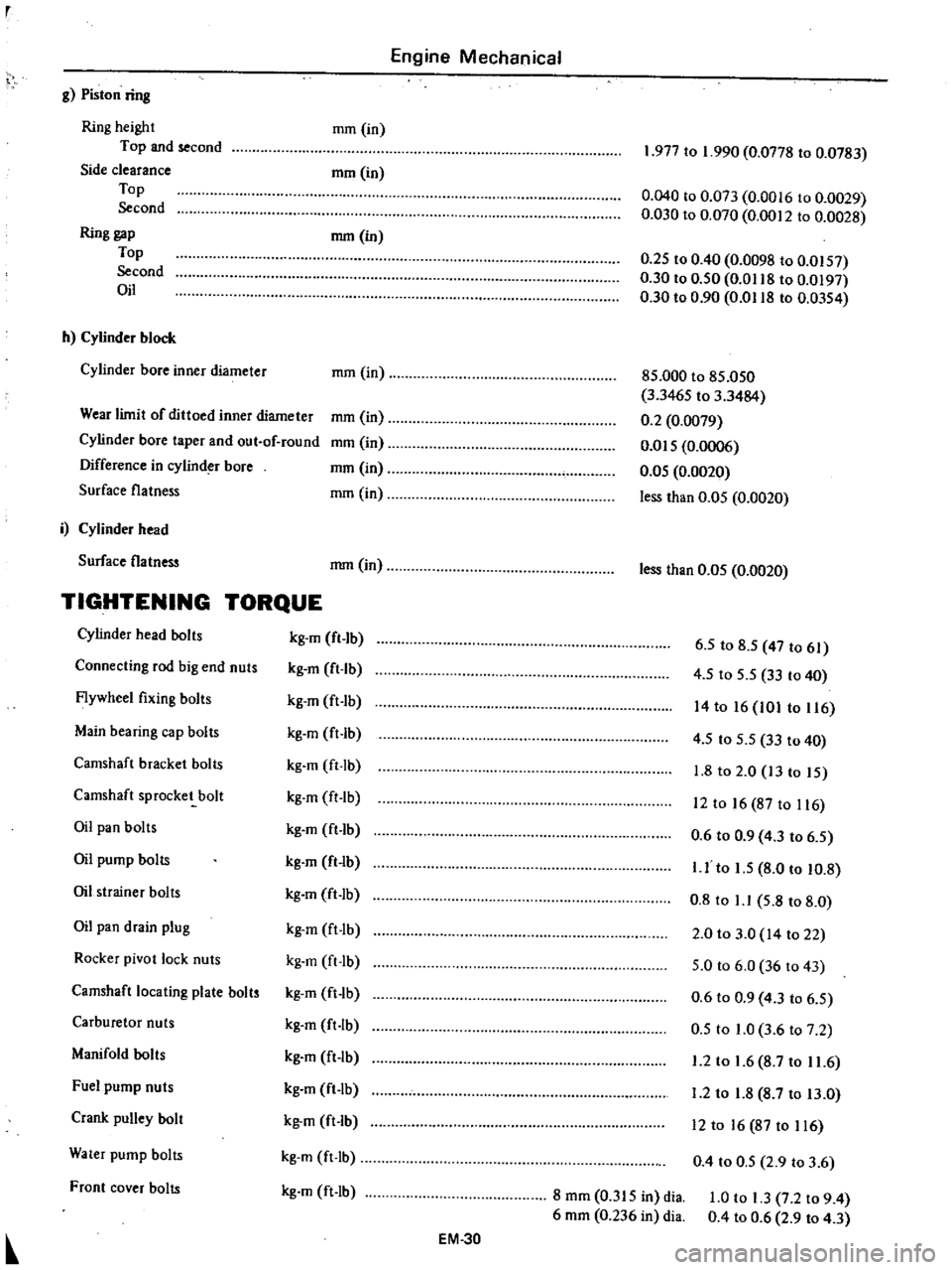
g
Piston
ring
Ring
height
Top
and
second
Side
clearance
Top
Second
Ring
gap
Top
Second
Oil
mm
in
mrn
in
mm
in
h
Cylinder
block
Cylinder
bore
inner
diameter
mm
in
Wear
limit
of
dittoed
inner
diameter
Cylinder
bore
taper
and
out
of
round
Difference
in
cylind
bore
Surface
flatness
mm
in
mm
in
mm
in
mm
in
i
Cylinder
head
Surface
flatness
mm
in
TIGHTENING
TORQUE
Cylinder
head
bolts
kg
m
fl
lb
Connecting
rod
big
end
nuts
kg
m
ft
Ib
Flywheel
fixing
bolts
kg
m
ft
Ib
Main
bearing
cap
bolts
kg
m
ft
lb
Camshaft
bracket
bolts
kg
m
ft
lb
Camshaft
sprocket
bolt
kg
m
ft
lb
Oil
pan
bolts
kg
m
ft
1b
Oil
pump
bolts
kg
m
ft
lb
Oil
strainer
bolts
kg
m
ft
lb
Oil
pan
drain
plug
kg
m
ft
lb
Rocker
pivot
lock
nuts
kg
m
ft
Ib
Camshaft
locating
plate
bolts
kg
m
ft
lb
Carburetor
nuts
kg
m
ft
lb
Manifold
bolts
kg
m
ft
lb
Fuel
pump
nuts
kg
m
ft
lb
Crank
pulley
bolt
kg
m
ft
lb
Water
pump
bolts
kg
m
ft
Ib
Front
cover
bolts
kg
m
ft
lb
EM
30
1
977
to
1
990
0
0778
to
0
0783
0
040
to
0
073
0
0016
to
0
0029
0
030
to
0
070
0
0012
to
0
0028
0
25
to
0
40
0
0098
to
0
0157
0
30
to
0
50
0
0118
to
0
0197
0
30
to
0
90
0
0118
to
0
0354
85
000
to
85
050
3
3465
to
3
3484
0
2
0
0079
om
5
0
0006
0
05
0
0020
less
than
0
05
0
0020
less
than
0
05
0
0020
6
5
to
8
5
47
to
61
4
5
to
5
5
33
to
40
14
to
16
101
to
116
4
5
to
5
5
33
to
40
1
8
to
2
0
13
to
15
12
to
16
87
to
116
0
6
to
0
9
4
3
to
6
5
I
J
to
1
5
8
0
to
10
8
0
8
to
1
1
5
8
to
8
0
2
0
to
3
0
14
to
22
5
0
to
6
0
36
to
43
0
6
to
0
9
4
3
to
6
5
0
5
to
1
0
3
6
to
7
2
1
2
to
1
6
8
7
to
11
6
1
2
to
1
8
8
7
to
13
0
12
to
16
87
to
116
0
4
to
0
5
2
9
to
3
6
8
mm
0
315
in
dia
6
mm
0
236
in
dia
1
0
to
1
3
7
2
to
9
4
0
4
to
0
6
2
9
to
4
3
Page 92 of 537
The
pump
shaft
is
supported
by
a
double
row
of
ball
bearings
press
fit
in
an
aluminum
die
cast
pump
body
The
bearings
are
permanently
lubricated
and
sealed
to
prevent
loss
of
lubricant
and
entry
of
dirt
The
pump
is
provided
with
an
impeller
which
turns
on
a
steel
shaft
The
steel
shaft
rotates
together
with
the
torque
coupling
wheeL
The
volute
chamber
is
built
in
the
engine
front
cover
assembly
The
inlet
of
the
pump
is
connected
to
the
radiator
s
lower
tank
by
a
hose
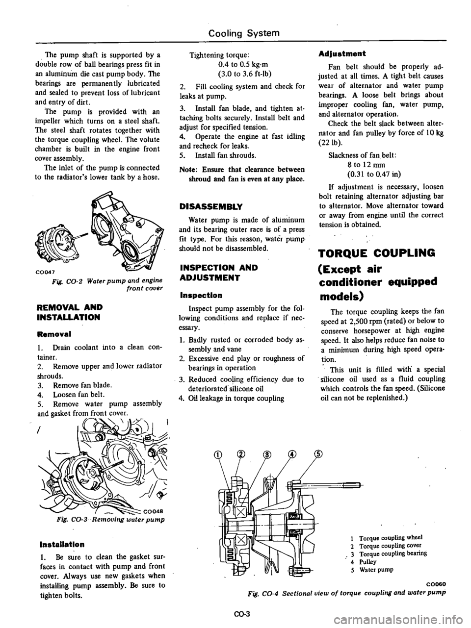
i
o
CQ047
Fig
CO
2
Water
pump
and
engine
front
cover
REMOVAL
AND
INSTALLATION
Removal
in
to
a
clean
con
assembly
I
CQ048
Fig
CO
3
Removing
water
pump
Installation
1
Be
sure
to
clean
the
gasket
sur
faces
in
contact
with
pump
and
front
cover
Always
use
new
gaskets
when
installing
pump
assembly
Be
sure
to
tighten
bolts
Cooling
System
Tightening
torque
0
4
to
0
5
kg
m
3
0
to
3
6
ft
lb
2
Fill
cooling
system
and
check
for
leaks
at
pump
3
Install
fan
blade
and
tighten
at
taching
bolts
securely
Install
belt
and
adjust
for
specified
tension
4
Operate
the
engine
at
fast
idling
and
recheck
for
leaks
5
Install
fan
shrouds
Note
Ensure
that
clearance
between
shroud
and
Can
is
even
at
any
place
DISASSEMBLY
Water
pump
is
made
of
aluminum
and
its
bearing
outer
race
is
of
a
press
fit
type
For
this
reason
water
pump
should
not
be
disassembled
INSPECTION
AND
ADJUSTMENT
Inspection
Inspect
pump
assembly
for
the
fol
lowing
conditions
and
replace
if
nee
essary
1
Badly
rusted
or
corroded
body
as
sembly
and
vane
2
Excessive
end
play
or
roughness
of
bearings
in
operation
3
Reduced
cooling
efficiency
due
to
deteriorated
silicone
oil
4
Oil
leakage
in
torque
coupling
Adjustment
Fan
belt
should
be
properly
ad
justed
at
all
times
A
tight
belt
causes
wear
of
alternator
and
water
pump
bearings
A
loose
belt
brings
about
improper
cooling
fan
water
pump
and
alternator
operation
Check
the
belt
slack
between
alter
nator
and
fan
pulley
by
force
of
10
kg
22
lb
Slackness
of
fan
belt
8
to
12
mm
0
31
to
0
47
in
If
adjustment
is
necessary
loosen
bolt
retaining
alternator
adjusting
bar
to
alternator
Move
alternator
toward
or
away
from
engine
until
the
correct
tension
is
obtained
TORQUE
COUPLING
Except
air
conditioner
equipped
models
The
torque
coupling
keeps
the
fan
speed
at
2
500
rpm
rated
or
below
to
conserve
horsepower
at
high
engine
speed
It
also
helps
reduce
fan
noise
to
a
minimum
during
high
speed
opera
tion
This
unit
is
filled
with
a
special
silicone
oil
used
as
a
fluid
coupling
which
controls
the
fan
speed
Silicone
oil
can
not
be
replenished
1
Torque
coupling
wheel
2
Torque
coupling
cover
3
Torque
coupling
bearing
4
Pulley
5
Water
pump
C0060
Fig
CO
4
Sectional
view
of
torque
coupling
and
water
pump
00
3
Page 160 of 537
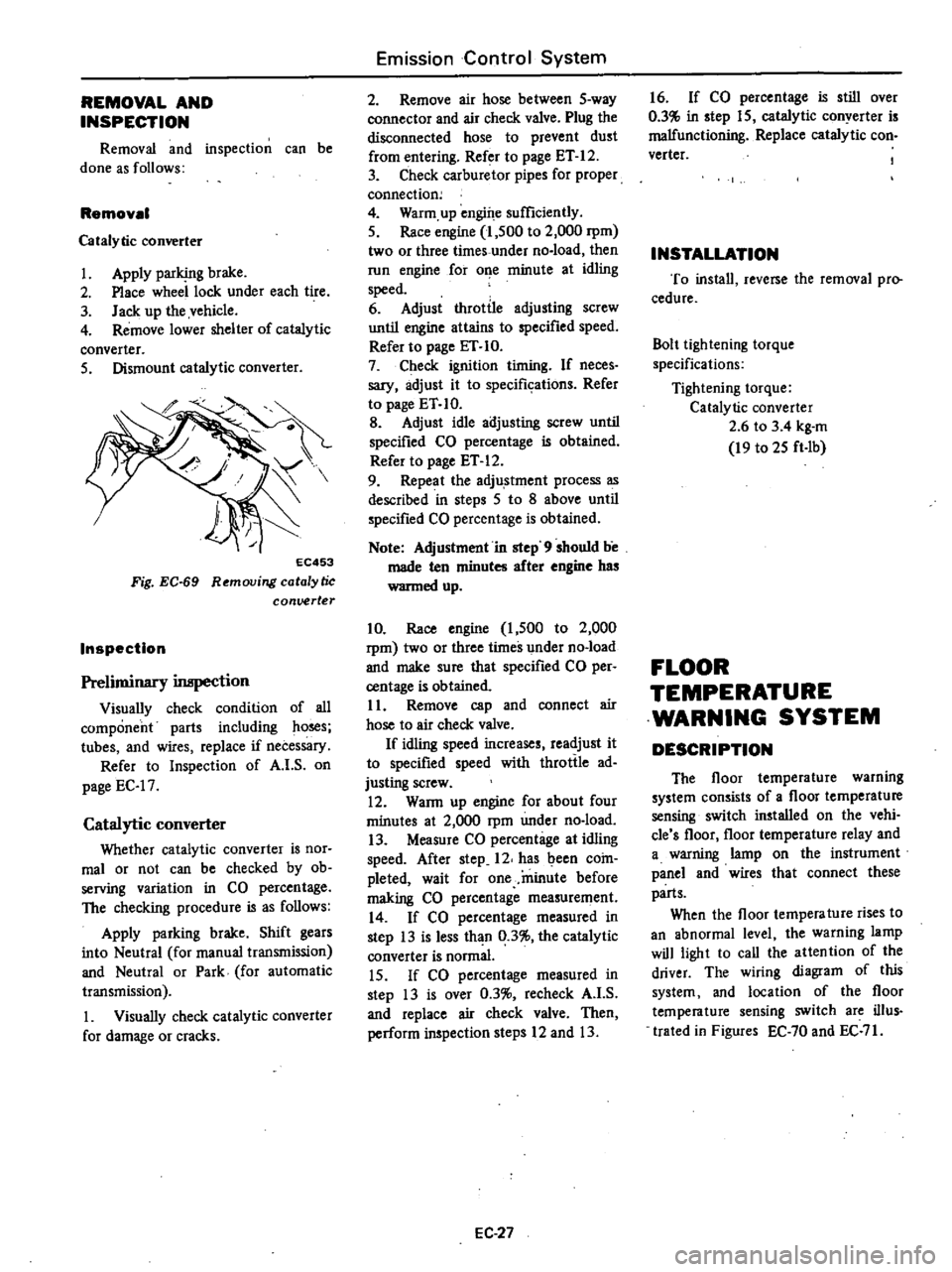
REMOVAL
AND
INSPECTION
Removal
and
inspection
can
be
done
as
follows
Removal
Catalytic
converter
1
Apply
parking
brake
2
Place
wheel
lock
under
each
tire
3
Jack
up
the
vehicle
4
Remove
lower
shelter
of
catalytic
converter
5
Dismount
catalytic
converter
EC453
Fig
EC
69
Removing
catalytic
conuerter
Inspection
Preliminary
inspection
Visually
check
condition
of
all
component
parts
including
ho
s
tubes
and
wires
replace
if
necessary
Refer
to
Inspection
of
A
I
S
on
page
EC
17
Catalytic
converter
Whether
catalytic
converter
is
nor
mal
or
not
can
be
checked
by
ob
serving
variation
in
CO
percentage
The
checking
procedure
is
as
follows
Apply
parking
brake
Shift
gears
into
Neutral
for
manual
transmission
and
Neutral
or
Park
for
automatic
transmission
1
Visually
check
catalytic
converter
for
damage
or
cracks
Emission
Control
System
2
Remove
air
hose
between
5
way
connector
and
air
check
valve
Plug
the
disconnected
hose
to
prevent
dust
from
entering
Refer
to
page
ET
12
3
Check
carburetor
pipes
for
proper
connection
4
Warm
up
engine
sufficiently
5
Race
engine
1
500
to
2
000
rpm
two
or
three
times
under
no
load
then
run
engine
for
o
e
minute
at
idling
speed
6
Adjust
throttle
adjusting
screw
until
engine
attains
to
specified
speed
Refer
to
page
ET
10
7
Check
ignition
timing
If
neces
sary
adjust
it
to
specifkations
Refer
to
page
ET
10
B
Adjust
idle
adjusting
screw
until
specified
CO
percentage
is
obtained
Refer
to
page
ET
12
9
Repeat
the
adju
stment
process
as
described
in
steps
5
to
8
above
until
specified
CO
percentage
is
obtained
Note
Adjustment
in
step
9
should
be
made
ten
minutes
after
engine
has
wanned
up
10
Race
engine
1
500
to
2
000
rpm
two
or
three
times
under
no
load
and
make
sure
that
specified
CO
per
centage
is
obtained
11
Remove
cap
and
connect
air
hose
to
air
check
valve
If
idling
speed
increases
readjust
it
to
specified
speed
with
throttle
ad
justing
screw
12
WaRn
up
engine
for
about
four
minutes
at
2
000
rpm
under
no
load
13
Measure
CO
percentage
at
idling
speed
After
step
12
has
been
coin
pleted
wait
for
one
minute
before
making
CO
percentage
measurement
14
If
CO
percentage
measured
in
step
13
is
less
than
0
3
the
catalytic
converter
is
normal
15
If
CO
percentage
measured
in
step
13
is
over
0
3
recheck
A
I
S
and
replace
air
check
valve
Then
perform
inspection
steps
12
and
13
EC
27
16
If
CO
percentage
is
still
over
0
3
in
step
15
catalytic
conyerter
is
malfunctioning
Replace
catalytic
con
verter
INSTALLATION
To
install
reverse
the
removal
pro
cedure
Bolt
lightening
torque
specifications
Tightening
torque
Catalytic
converter
2
6
to
3
4
kg
m
19
to
25
ft
Ib
FLOOR
TEMPERATURE
WARNING
SYSTEM
DESCRIPTION
The
floor
temperature
warning
system
consists
of
a
floor
temperature
sensing
switch
installed
on
the
vehi
cle
s
floor
floor
temperature
relay
and
a
warning
lamp
on
the
instrument
panel
and
wires
that
connect
these
parts
When
the
floor
tempera
ture
rises
to
an
abnormal
level
the
warning
lamp
will
light
to
call
the
attention
of
the
driver
The
wiring
diagram
of
this
system
and
location
of
the
floor
temperature
sensing
switch
are
ilIus
trated
in
Figures
EC
70
and
EC
71
Page 173 of 537
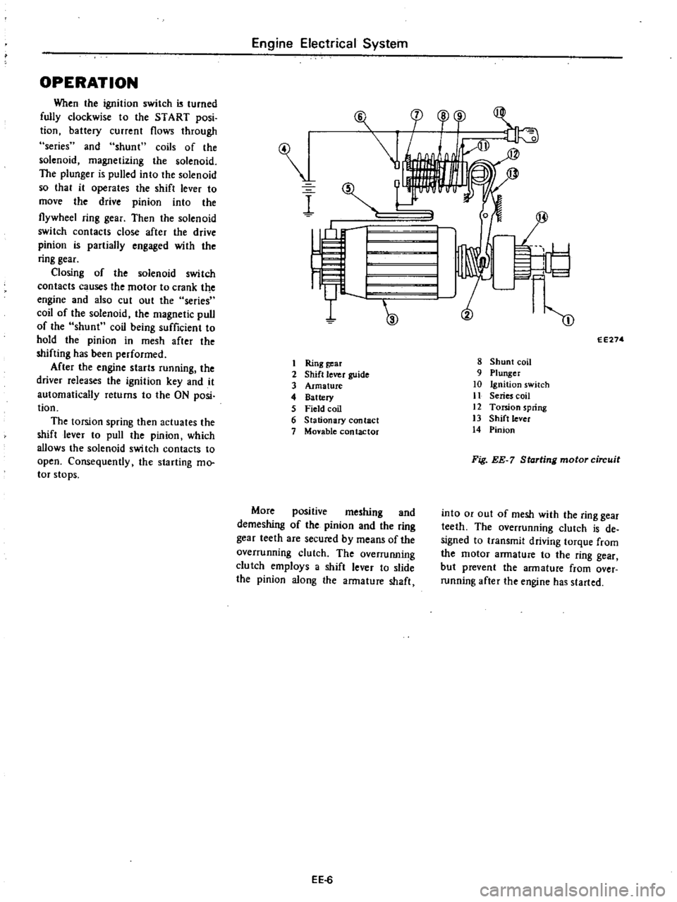
OPERATION
When
the
ignition
switch
turned
fully
clockwise
to
the
START
posi
tion
battery
current
flows
through
series
and
shunt
coils
of
the
solenoid
magnetizing
the
solenoid
The
plunger
is
pulled
into
the
solenoid
so
that
it
operates
the
shift
lever
to
move
the
drive
pinion
into
the
flywheel
ring
gear
Then
the
solenoid
switch
contacts
close
after
the
drive
pinion
is
partially
engaged
with
the
ring
gear
Closing
of
the
solenoid
switch
contacts
c
uses
the
motor
to
crank
the
engine
and
also
cut
out
the
series
coil
of
the
solenoid
the
magnetic
pull
of
the
shunt
coil
being
sufficient
to
hold
the
pinion
in
mesh
after
the
shifting
has
been
performed
After
the
engine
starts
running
the
driver
releases
the
ignition
key
and
it
automatically
returns
to
the
ON
posi
tion
The
torsion
spring
then
actuates
the
shift
lever
to
pull
the
pinion
which
allows
the
solenoid
swi
tch
contacts
to
open
Consequently
the
starting
mo
tor
stops
Engine
Electrical
System
I
I
Ring
gear
2
Shift
lever
guide
3
Armature
4
Battery
5
Field
coil
6
Stationary
contact
7
Monble
contactor
More
positive
meshing
and
demeshing
of
the
pinion
and
the
ring
gear
teeth
are
secured
by
means
of
the
overrunning
clutch
The
overruIUling
clutch
employs
a
shift
lever
to
slide
the
pinion
along
the
armature
shaft
EE
6
F
l
cp
o
r
1
I
I
W
m
EE274
8
Shunt
coil
9
Plunger
10
Ignition
switch
11
Series
coil
12
Torsion
spring
13
Shift
lever
14
Pinion
Fig
EE
7
Starting
motor
circuit
into
or
out
of
mesh
with
the
ring
gear
teeth
The
overrunning
clutch
is
de
signed
to
transmit
driving
torque
from
the
motor
armature
to
the
ring
gear
but
prevent
the
armature
from
over
running
after
the
engine
has
started
Page 224 of 537
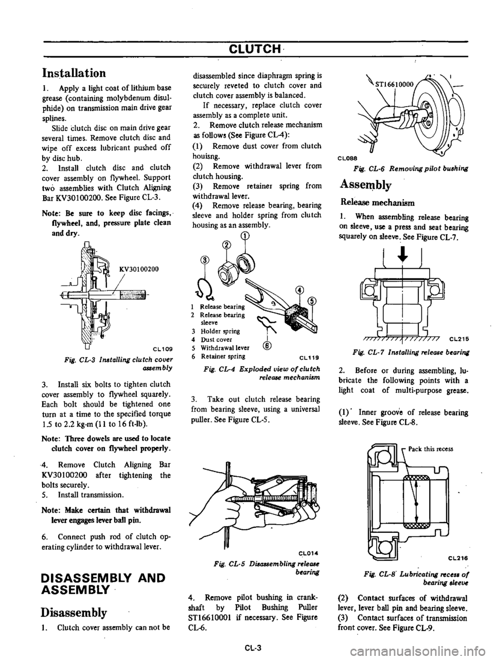
Installation
I
Apply
a
light
coat
of
lithium
base
grease
containing
molybdenum
disul
phide
on
transmission
main
drive
gear
splines
Slide
clutch
disc
on
main
drive
gear
several
times
Remove
clutch
disc
and
wipe
off
excess
lubricant
pushed
off
by
disc
hub
2
Install
clutch
disc
and
clutch
cover
assembly
on
flywheel
Support
two
assemblies
with
Clutch
Aligning
Bar
KV30100200
See
Figure
CL
3
Note
Be
sure
to
keep
disc
facings
flywheel
and
pressure
plate
clean
and
dry
7
00
R
rr
CL109
Fig
CL
3
l
talling
clutch
cover
assem
bly
3
Install
six
bolts
to
tighten
clutch
cover
assembly
to
flywheel
squarely
Each
bolt
should
be
tightened
one
turn
at
a
time
to
the
specified
torque
15
to
2
2
kg
m
II
to
16
ft
Ib
Note
Three
dowels
are
used
to
locate
clutch
cover
on
flywheel
properly
4
Remove
Clutch
Aligning
Bar
KV30100200
after
tightening
the
bolts
securely
5
Install
transmission
Note
Make
certain
that
withdrawal
lever
engages
lever
ball
pin
6
Connect
push
rod
of
clutch
op
erating
cylinder
to
withdrawal
lever
DISASSEMBLY
AND
ASSEMBLY
Disassembly
I
Clutch
cover
assembly
can
not
be
CLUTCH
disassembled
since
diaphragm
spring
is
securely
reveted
to
clutch
cover
and
clutch
cover
assembly
is
balanced
If
necessary
replace
clutch
cover
assembly
as
a
complete
unit
2
Remove
clutch
release
mechanism
as
follows
See
Figure
CL4
1
Remove
dust
cover
from
clutch
houisng
2
Remove
withdrawal
lever
from
clutch
housing
3
Remove
retainer
spring
from
withdrawal
lever
4
Remove
release
bearing
bearing
sleeve
and
holder
spring
from
clu
tch
housing
as
an
assembly
1
lo
1
Release
bearing
2
Release
bearing
sleeve
3
Holder
spring
4
Dust
cover
5
Withdrawal
lever
6
Retainer
spring
CL119
Fig
CL
4
Exploded
view
of
clutch
releaae
mechaniam
3
Take
out
clutch
release
bearing
from
bearing
sleeve
using
a
universal
puller
See
Figure
CL
5
C
L014
Fig
CL
5
D
embling
rele
e
b
aring
4
Remove
pilot
bushing
in
crank
shaft
by
Pilot
Bushing
Puller
ST16610001
if
necessary
See
Figure
CL
6
CL3
CLOSS
Fig
CL
6
Removing
pilot
bu
hing
Asse
bly
Release
mechaniam
1
When
assembling
release
bearing
on
sleeve
use
a
press
and
seat
bearing
squarely
on
sleeve
See
Figure
CL
7
l
J
I
CL215
I
1
J
1
Fig
CL
7
1
tailing
rele
e
bearing
2
Before
or
during
assembling
lu
bricate
the
following
points
with
a
light
coat
of
multi
purpose
grease
I
Inner
groove
of
release
bearing
sleeve
See
Figure
CL
8
Lf
I
n
JQt
CL216
Fig
CL
B
Lu
bricating
ee
of
bearing
slee
2
Contact
surfaces
of
withdrawal
lever
lever
ball
pin
and
bearing
sleeve
3
Contact
surfaces
of
transmission
front
cover
See
Figure
CL
9
Page 230 of 537
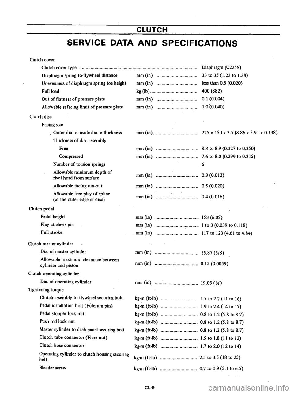
CLUTCH
SERVICE
DATA
AND
SPECIFICATIONS
Clutch
cover
Clu
tch
cover
type
Diaphragm
spring
to
flywheel
distance
Unevenness
of
diaphragm
spring
toe
height
Full
load
Out
of
flatness
of
pressure
plate
Allowable
refacing
limit
of
pressure
plate
Clutch
disc
Facing
size
Outer
dia
x
inside
dia
x
thickness
Thickness
of
disc
assembly
Free
Compressed
Number
of
torsion
springs
Allowable
minimum
depth
of
rivet
head
from
surface
Allowable
facing
run
out
Allowable
free
play
of
spline
at
the
outer
edge
of
disc
Clutch
pedal
Pedal
height
Play
at
clevis
pin
Full
stroke
Clutch
master
cylinder
Dia
of
master
cylinder
Allowable
maximum
clearance
between
cylinder
and
piston
Clutch
operating
cylinder
Dia
of
operating
cylinder
Tightening
torque
Clutch
assembly
to
flywheel
securing
bolt
Pedal
installation
bolt
Fulcrum
pin
Pedal
stopper
lock
nut
Push
rod
lock
nut
Master
cylinder
to
dash
panel
securing
bolt
Clutch
tube
connector
Flare
nut
Clutch
hose
connector
Operating
cylinder
to
clutch
housing
securing
bolt
Bleeder
screw
mm
in
mm
in
kg
Qb
mm
in
mm
in
Diaphragm
C225S
33
to
35
1
23
to
1
38
less
than
0
5
0
020
400
882
0
1
0
004
1
0
0
040
mm
in
225
x
150
x
3
5
8
86
x
5
91
x
0
138
mm
in
mm
in
8
3
to
8
9
0
327
to
0
350
7
6
to
8
0
0
299
to
0
315
6
0
3
0
012
0
5
0
020
0
4
0
016
mm
in
mm
in
mm
in
mm
in
153
6
02
mm
in
I
to
3
0
039
to
0
118
mm
in
117
to
123
4
61
to
4
84
mm
in
15
87
5
8
mm
in
0
15
0
0059
mm
in
19
05
Yo
kg
m
ft
lb
1
5
to
2
2
lito
16
kg
m
ft
Ib
1
9
to
2
4
14
to
17
kg
m
ft
b
0
8
to
1
2
5
8
to
8
7
kg
m
ft
lb
0
8
to
1
2
5
8
to
8
7
kg
m
ft
Ib
0
8
to
1
2
5
8
to
8
7
kg
m
ft
lb
1
5
to
1
8
11
to
13
kg
m
ft
lb
1
7
to
2
0
12
to
14
kg
m
ft
lb
2
5
to
3
5
18
to
25
kg
m
ft
Ib
0
7
to
0
9
5
1
to
6
5
CL
9
Page 304 of 537
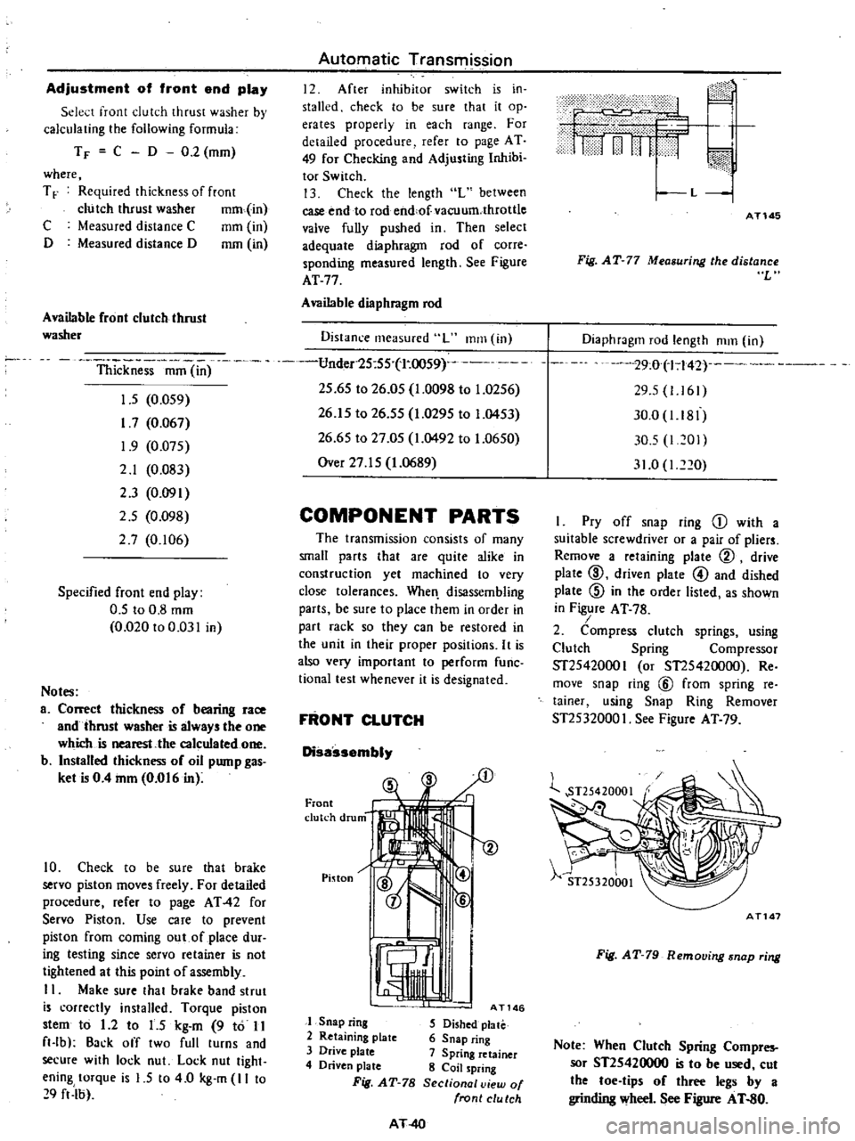
Adjustment
of
front
end
play
Sele
t
front
dutch
thrust
washer
by
calculating
the
following
formula
T
F
C
D
0
2
mm
where
T
F
Required
thickness
of
front
clutch
thrust
washer
mm
in
C
Measured
distance
C
mm
in
D
Measured
distance
D
mm
in
Available
front
clutch
thrust
washer
Thickness
mm
in
1
5
0
059
I
7
0
067
1
9
0
075
2
1
0
083
2
3
0
091
2
5
0
098
27
0
106
Specified
front
end
play
0
5
to
0
8
mm
0
020
to
0
031
in
Notes
a
Correct
thickness
of
bearing
race
and
thrust
washer
is
always
the
one
which
is
nearest
the
calculated
one
b
Installed
thickness
of
oil
pump
gas
ket
is
0
4
mm
0
016
in
10
Check
to
be
sure
that
brake
servo
piston
moves
freely
For
detailed
ptocedure
refer
to
page
AT
42
for
Servo
Piston
Use
care
to
prevent
piston
from
coming
out
of
place
dUI
ing
testing
since
servo
retainer
is
not
tightened
at
this
point
of
assembly
II
Make
sure
that
brake
band
strut
is
correctly
installcd
Torque
piston
stem
to
1
2
to
1
5
kg
m
9
to
11
f1
lb
Back
off
two
full
lurns
and
secure
with
lock
nut
Lock
nut
tight
ening
torque
is
1
5
to
4
0
kg
m
II
to
9
f1
lb
Automatic
Transmission
12
After
inhibitor
switch
is
in
stalled
check
to
be
sure
that
it
op
erates
properly
in
each
range
For
detailed
procedure
refer
to
page
AT
49
for
Checl
ing
and
Adjusting
Inhibi
tor
Switch
13
Check
the
length
L
between
case
end
to
rod
end
ofvacuum
throllle
valve
fully
pushed
in
Then
select
adequate
diaphragm
rod
of
corre
sponding
measured
length
See
Figure
AT
77
Available
diaphragm
rod
Distanl
e
measured
L
ITIm
in
Under25
55
l
OO59
25
65
to
26
05
1
0098
to
1
0256
26
15
to
26
55
1
0295
to
1
0453
26
65
to
27
05
1
0492
to
1
0650
Over
27
15
1
0689
COMPONENT
PARTS
The
transmission
cons
sts
of
many
small
parts
that
are
quite
alike
in
construction
yet
machined
to
very
close
tolerances
When
disassembling
parts
be
sure
to
place
them
in
order
in
part
rack
so
they
can
be
restored
in
the
unit
in
their
proper
positions
It
is
also
very
important
to
perform
func
tianal
test
whenever
it
is
designated
FRONT
CLUTCH
Disassembly
Front
clutch
drum
I
Pinon
lcz
t
AT146
1
Snap
ring
2
Retaining
plate
3
Drive
plate
4
Driven
plate
Fit
AT
78
S
Dished
plate
6
Snap
ring
7
Spring
retainer
8
Coil
spring
Sectional
view
of
front
clu
tch
AT
40
i
i
n
H
I
I
ni
c
A
i
iif
L
1
AT145
Fig
AT
77
Measuring
the
distance
L
Diaphragm
rod
length
mm
in
29
00
142
u
29
5
1161
30
0
1
81
30
5
1201
31
0
I
O
I
Pry
off
snap
ring
D
with
a
suitable
screwdriver
or
a
pair
of
pliers
Remove
a
retaining
plate
@
drive
plate
CID
driven
plate
@
and
dished
plate
@
in
the
order
listed
as
shown
in
Figure
AT
78
I
2
Compress
clutch
springs
using
Clutch
Spring
Compressor
ST25420001
or
51
25420000
Re
move
snap
ring
@
from
spring
re
tainer
using
Snap
Ring
Remover
ST2532000
I
See
Figure
AT
79
AT147
Fig
AT
79
Removing
snap
ring
Note
When
Clutch
Spring
Compres
sor
ST25420000
is
to
be
used
cut
the
toe
tips
of
three
legs
by
a
grinding
wheel
See
Figure
AT
80
Page 314 of 537
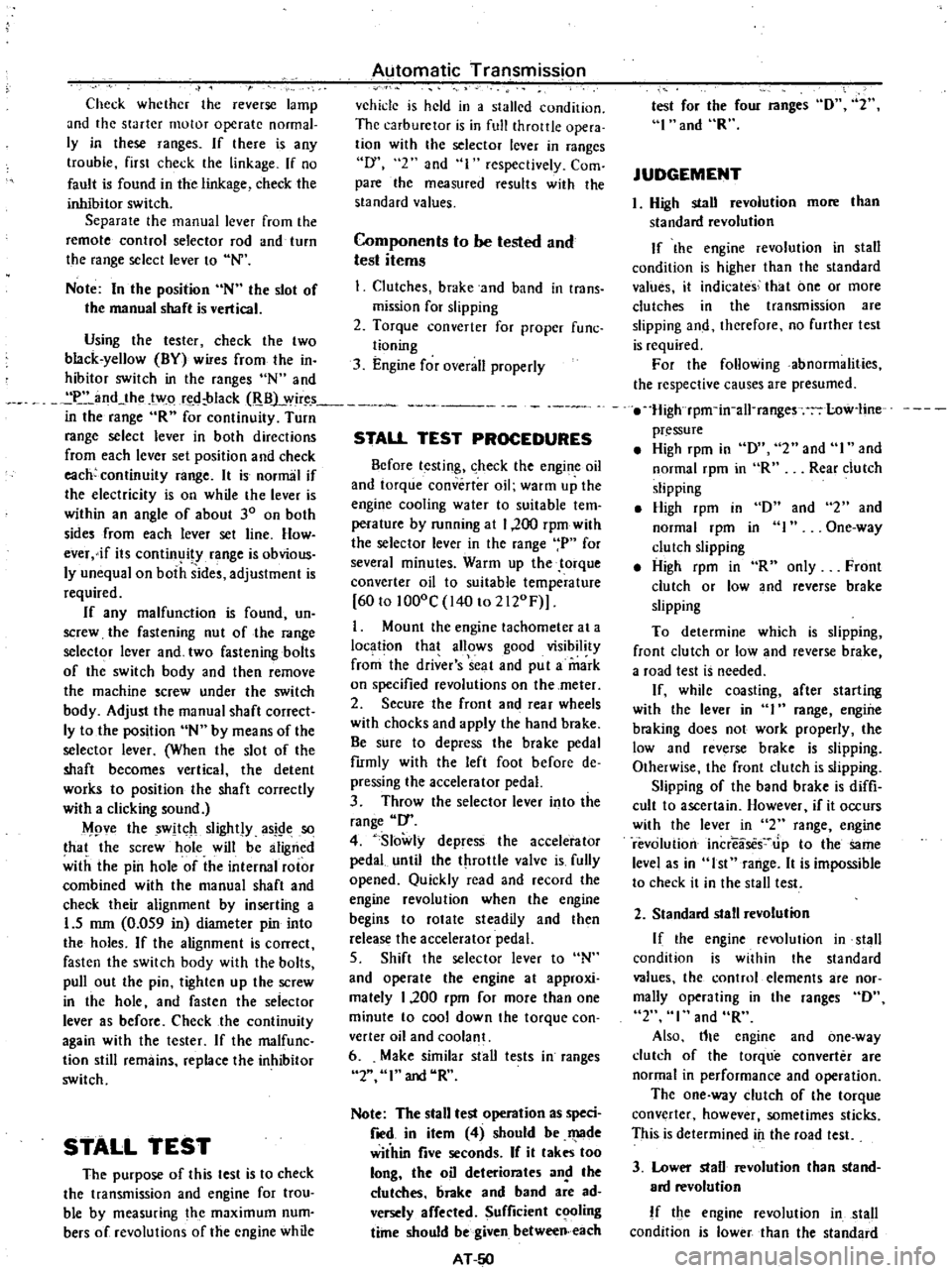
Using
the
tester
check
the
two
black
yellow
BY
wires
from
the
in
hibitor
switch
in
the
ranges
N
and
I
and
the
tw
re
d
black
RBj
wir
s
in
the
range
R
for
continuity
Turn
range
select
lever
in
both
directions
from
each
lever
set
position
and
check
each
continuity
range
It
is
normal
if
the
electricity
is
on
while
the
lever
is
within
an
angle
of
about
30
on
both
sides
from
each
lever
set
line
How
ever
if
its
continl
ity
range
is
obvious
ly
unequal
on
both
sides
adjustment
is
required
If
any
malfunction
is
found
un
screw
the
fastening
nut
of
the
range
selector
lever
and
two
fastening
bolts
of
the
switch
body
and
then
remove
the
machine
screw
under
the
switch
body
Adjust
the
manual
shaft
correct
ly
to
the
position
N
by
means
of
the
selector
lever
When
the
slot
of
the
shaft
becomes
vertical
the
detent
works
to
position
the
shaft
correctly
with
a
clicking
sound
MSlVe
the
switch
slightly
asj
Je
so
that
the
screw
hole
will
be
aligned
with
the
pin
hole
of
the
internal
rotor
combined
with
the
manual
shaft
and
check
their
alignment
by
inserting
a
1
5
mm
0
059
in
diameter
pin
into
the
holes
If
the
alignment
is
correct
fasten
the
switch
body
with
the
bolts
pull
out
the
pin
tighten
up
the
screw
in
the
hole
and
fasten
the
selector
lever
as
before
Check
the
continuity
again
with
the
tester
If
the
malfunc
tion
still
remains
replace
the
inhibitor
switch
Chcck
whether
the
reverse
lamp
and
the
starter
motor
operate
normal
ly
in
these
ranges
If
Ihere
is
any
lrouble
first
check
the
linkage
If
no
fault
is
found
in
the
linkage
check
the
inhibitor
switch
Separate
the
manual
lever
from
Ihe
remote
control
selector
rod
and
turn
the
range
selcct
lever
to
N
Note
In
the
position
N
the
slot
of
the
manual
shaft
is
vertical
STALL
TEST
The
purpose
of
this
test
is
to
check
the
transmission
and
engine
for
trou
ble
by
measuring
the
maximum
num
bers
of
revolutions
of
the
engine
while
Automatic
Transmission
vehicle
is
held
in
a
stalled
condition
The
carburctor
is
in
full
throttle
opera
tion
with
the
selector
lever
in
ranges
f
2
and
I
respectively
Com
pare
the
measured
results
with
the
slandard
values
Components
to
be
tested
and
test
items
I
Clutches
brake
and
band
in
trans
mission
for
slipping
2
Torque
converter
for
proper
fune
tioning
3
Engine
for
overall
properly
STALL
TEST
PROCEDURES
Before
Icsting
c
heck
the
engine
oil
and
torque
converter
oil
warm
up
the
engine
cooling
water
to
suitable
tem
perature
by
running
at
1
200
rpm
with
the
selector
lever
in
the
range
P
for
several
minutes
Warm
up
the
torque
converter
oil
to
suitable
temperature
6010
1000C
140
to
2l20F
I
Mount
the
engine
tachometer
at
a
location
that
allows
good
visibility
fro
the
dri
er
s
seat
and
put
a
mark
on
specified
revolutions
on
the
meter
2
Secure
the
front
and
rear
wheels
with
chocks
and
apply
the
hand
brake
Be
sure
to
depress
the
brake
pedal
fumly
with
the
left
foot
before
de
pressing
the
accelerator
pedal
3
Throw
the
selector
lever
into
the
range
1
4
Slowly
depress
the
accelerator
pedal
until
the
throttle
valvc
is
fully
opened
Quickly
read
and
record
the
engine
revolution
when
the
engine
begins
to
rotate
steadily
and
then
release
the
accelerator
pedal
5
Shift
the
selector
lever
to
N
and
operate
the
engine
at
approxi
mately
1
200
rpm
for
more
than
one
minute
to
cool
down
the
torque
con
ver
ter
oil
and
coolant
6
Make
similar
stall
tests
in
ranges
2
I
and
RIO
Note
The
stall
test
operation
as
speci
f
d
in
item
4
should
be
I
l3de
wiihin
five
seconds
If
it
takes
too
long
the
oil
deteriorates
an
the
clutches
brake
and
band
are
ad
versely
affected
Sufficient
cooling
time
should
be
given
between
each
AT
5O
test
for
the
four
ranges
0
2
I
and
R
JUDGEMENT
High
stall
revolution
more
than
standard
revolution
If
the
engine
revolution
in
stall
condition
is
higher
than
the
standard
values
it
indicates
that
one
or
more
clutches
in
the
transmission
are
slipping
and
therefore
no
further
test
is
required
For
the
following
abnormalities
the
respective
causes
are
presumed
High
rpm
in
all
ranges
low
Iine
pressure
High
rpm
in
D
2
and
I
and
normal
rpm
in
R
Rear
clutch
slipping
High
rpm
in
0
and
normal
rpm
in
I
clutch
slipping
High
rpm
in
R
only
Front
clutch
or
low
and
reverse
brake
slipping
To
determine
which
is
slipping
front
clutch
or
low
and
reverse
brake
a
road
test
is
nceded
If
whilc
coasting
after
starting
with
the
lever
in
1
range
engine
braking
does
not
work
properly
the
low
and
reverse
brake
is
slipping
Otherwise
the
front
clutch
is
slipping
Slipping
of
the
band
brake
is
diffi
cult
to
ascertain
However
if
it
occurs
with
the
lever
in
2
range
engine
revolution
increases
Jp
to
thesarne
level
as
in
I
strange
It
is
impossible
to
check
it
in
the
stall
test
2
and
One
way
2
Standard
stall
revolution
If
the
engine
revolution
in
stall
condition
is
within
the
standard
values
the
control
elements
are
nor
mally
operating
in
the
ranges
0
2
I
and
R
Also
tIle
engine
and
one
way
clutch
of
the
torque
converter
are
normal
in
performance
and
operation
The
one
way
clutch
of
the
torque
converter
however
sometimes
sticks
This
is
determined
in
the
road
test
3
Lower
stall
revolution
than
stand
ard
revolution
If
the
engine
revolution
in
stall
condition
is
lower
than
the
standard