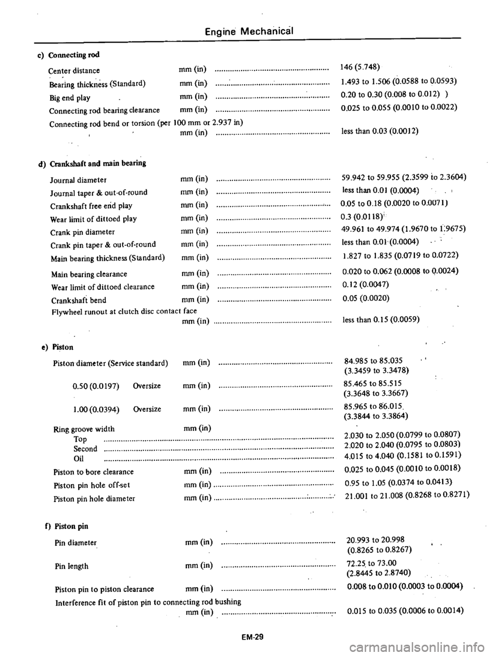
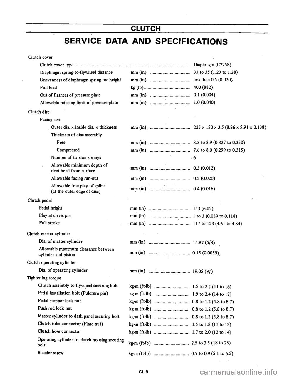
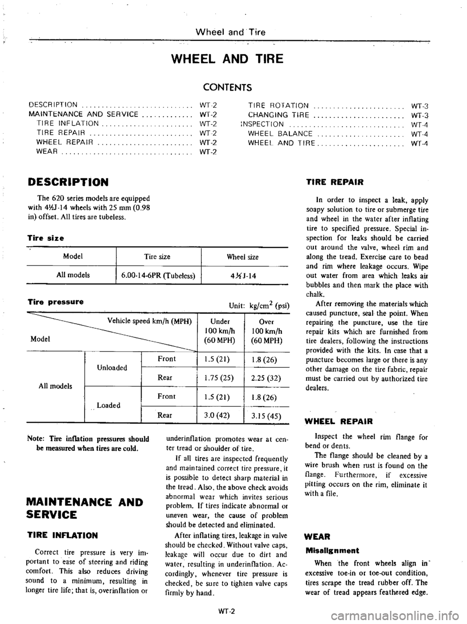
wheel size DATSUN PICK-UP 1977 Service Manual
[x] Cancel search | Manufacturer: DATSUN, Model Year: 1977, Model line: PICK-UP, Model: DATSUN PICK-UP 1977Pages: 537, PDF Size: 35.48 MB
Page 74 of 537

Engine
Mechanical
c
Connecting
rod
Center
distance
mm
in
Bearing
thickness
Standard
mm
in
Big
end
play
mm
in
Connecting
rod
bearing
clearance
mm
in
Connecting
rod
bend
or
torsion
per
100
mm
or
2
937
in
mm
in
d
Crankshaft
and
main
bearing
Journal
diameter
Journal
taper
out
of
round
Crankshaft
free
end
play
Wear
limit
of
dittoed
play
Crank
pin
diameter
Crank
pin
taper
out
of
round
Main
bearing
thickness
StJlndard
146
5
748
1
493
to
1
506
0
0588
to
0
0593
0
20
to
0
30
0
008
to
0
012
0
D25
to
0
055
0
0010
to
0
0022
less
than
0
03
0
0012
mm
in
mm
in
mm
in
mm
in
mm
in
mm
in
mm
in
59
942
to
59
955
2
3599
io
2
3604
less
than
0
0
I
0
0004
0
05
to
0
18
0
0020
to
0
0071
0
3
0
0118
49
961
to
49
974
1
9670
to
1
9675
less
than
0
01
0
0004
1
827
to
1
835
0
0719
to
0
0722
0
020
to
0
062
0
0008
to
0
0024
0
12
0
0047
0
05
0
0020
Main
bearing
clearance
mm
in
Wear
limit
of
dittoed
clearance
mm
in
Crankshaft
bend
mm
in
Flywheel
runout
at
clutch
disc
contact
face
mm
in
e
Piston
Pistondiarneter
Service
standard
0
50
0
0197
Oversize
1
00
0
0394
Oversize
Ring
groove
width
Top
Second
Oil
Piston
to
bore
clearance
Piston
pin
hole
off
set
Piston
pin
hole
diameter
f
Piston
pin
Pin
diameter
Pin
length
less
than
0
15
0
0059
mm
in
84
985
to
85
035
3
3459
to
3
3478
85
465
to
85
515
3
3648
to
3
3667
85
965
to
86
015
3
3844
to
3
3864
2
030
to
2
050
0
0799
to
0
0807
2
020
to
2
040
0
0795
to
0
0803
4
015
to
4
040
0
1581
to
0
1591
0
Q25
to
0
045
0
0010
to
0
0018
0
95
to
1
05
0
0374
to
0
0413
21
001
to
21
008
0
8268
to
0
8271
mm
in
mm
in
mm
in
mm
in
mm
in
mm
in
mm
in
20
993
to
20
998
0
8265
to
0
8267
72
25
to
73
00
2
8445
to
2
8740
0
008
to
om
0
0
0003
to
0
0004
mm
in
Piston
pin
to
piston
clearance
mm
in
Interference
fit
of
piston
pin
to
connecting
rod
bushing
mm
in
om
5
to
0
035
0
0006
to
0
00
I
4
EM
29
Page 230 of 537

CLUTCH
SERVICE
DATA
AND
SPECIFICATIONS
Clutch
cover
Clu
tch
cover
type
Diaphragm
spring
to
flywheel
distance
Unevenness
of
diaphragm
spring
toe
height
Full
load
Out
of
flatness
of
pressure
plate
Allowable
refacing
limit
of
pressure
plate
Clutch
disc
Facing
size
Outer
dia
x
inside
dia
x
thickness
Thickness
of
disc
assembly
Free
Compressed
Number
of
torsion
springs
Allowable
minimum
depth
of
rivet
head
from
surface
Allowable
facing
run
out
Allowable
free
play
of
spline
at
the
outer
edge
of
disc
Clutch
pedal
Pedal
height
Play
at
clevis
pin
Full
stroke
Clutch
master
cylinder
Dia
of
master
cylinder
Allowable
maximum
clearance
between
cylinder
and
piston
Clutch
operating
cylinder
Dia
of
operating
cylinder
Tightening
torque
Clutch
assembly
to
flywheel
securing
bolt
Pedal
installation
bolt
Fulcrum
pin
Pedal
stopper
lock
nut
Push
rod
lock
nut
Master
cylinder
to
dash
panel
securing
bolt
Clutch
tube
connector
Flare
nut
Clutch
hose
connector
Operating
cylinder
to
clutch
housing
securing
bolt
Bleeder
screw
mm
in
mm
in
kg
Qb
mm
in
mm
in
Diaphragm
C225S
33
to
35
1
23
to
1
38
less
than
0
5
0
020
400
882
0
1
0
004
1
0
0
040
mm
in
225
x
150
x
3
5
8
86
x
5
91
x
0
138
mm
in
mm
in
8
3
to
8
9
0
327
to
0
350
7
6
to
8
0
0
299
to
0
315
6
0
3
0
012
0
5
0
020
0
4
0
016
mm
in
mm
in
mm
in
mm
in
153
6
02
mm
in
I
to
3
0
039
to
0
118
mm
in
117
to
123
4
61
to
4
84
mm
in
15
87
5
8
mm
in
0
15
0
0059
mm
in
19
05
Yo
kg
m
ft
lb
1
5
to
2
2
lito
16
kg
m
ft
Ib
1
9
to
2
4
14
to
17
kg
m
ft
b
0
8
to
1
2
5
8
to
8
7
kg
m
ft
lb
0
8
to
1
2
5
8
to
8
7
kg
m
ft
Ib
0
8
to
1
2
5
8
to
8
7
kg
m
ft
lb
1
5
to
1
8
11
to
13
kg
m
ft
lb
1
7
to
2
0
12
to
14
kg
m
ft
lb
2
5
to
3
5
18
to
25
kg
m
ft
Ib
0
7
to
0
9
5
1
to
6
5
CL
9
Page 358 of 537

s
Install
tension
rod
at
rear
end
tighten
nut
to
make
the
distance
of
rubber
bushing
to
be
33
4
mm
1
315
in
and
torque
lock
nut
to
1
6
to
2
2
kg
m
12
to
16
ft
lb
6
Install
tension
rod
bracket
to
chassis
frame
bracket
and
torque
nut
to
1
6
to
2
2
kg
m
12
to
16
ft
lb
When
two
rubber
bushings
are
dif
ferent
in
size
arrange
adjusting
nut
Standard
dimension
is
11
0
mOl
0
433
in
as
shown
in
Figure
FA
16
Torque
lock
nut
to
1
6
to
2
2
kg
m
12
to
16
ft
lb
Il
0
11
0
0
433
t
lP
33
4
1
315
I
11
0
0
433
1
0
11
0
0
433
Adjusting
nut
Y
i
w
36
6
l
441
Unit
mm
in
FA235
Fig
FA
16
Tension
rod
detail
INSPECTION
I
Check
tension
rod
for
bend
and
the
thread
for
faulty
condition
Repair
or
replace
as
required
2
Check
bushing
rubber
for
wear
and
deterioration
Replace
if
neces
sary
TORSION
BAR
SPRING
REMOVAL
AND
INSTALLATION
Removal
1
Raise
vehicle
on
a
hoist
or
stands
2
Remove
wheel
3
Loosen
nuts
at
spring
anchor
bolt
Front
Axle
Front
Suspension
4
Remove
dust
cover
at
the
rear
end
of
torsion
bar
spring
and
detach
snap
ring
S
Withdraw
torsion
bar
spring
rear
ward
after
pulling
ou
t
anchor
arm
realWard
I
nstallalation
Install
torsion
bar
spring
in
the
reverse
sequence
of
removal
noting
the
following
instructions
I
Coat
grease
on
the
serrations
of
torsion
bar
spring
and
install
it
to
torque
arm
Note
Be
sure
to
install
right
and
left
torsion
bar
springs
correctly
They
can
be
identified
with
R
Right
and
L
Left
marked
on
the
end
surface
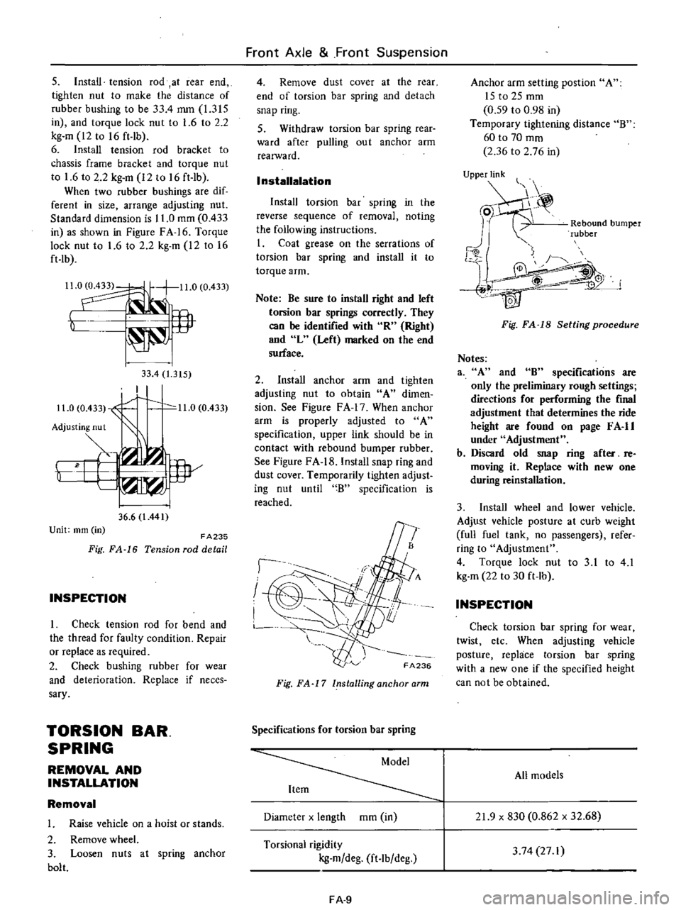
2
Install
anchor
arm
and
tighten
adjusting
nut
to
obtain
A
dimen
sion
See
Figure
F
A
17
When
anchor
arm
is
properly
adjusted
to
A
specification
upper
link
should
be
in
contact
with
rebound
bumper
rubber
See
Figure
FA
18
Install
snap
ring
and
dust
cover
Temporarily
tighten
adjust
ing
nut
until
B
specification
is
reached
I
I
I
FA236
Fig
FA
17
Installing
anchor
arm
Specifications
for
torsion
bar
spring
Diameter
x
length
mOl
in
Torsional
rigidity
kg
m
deg
ft
lb
deg
FA
9
Anchor
arm
setting
post
ion
A
ISt02Smm
0
59
to
0
98
in
Temporary
tightening
distance
B
60
to
70
mOl
2
36
to
2
76
in
UjPPje
Rebound
bumper
rubber
j
4W
Fig
FA
18
Setting
procedure
Notes
3
A
and
8
specifications
are
only
the
preliminary
rough
settings
directions
for
performing
the
final
adjustment
that
determines
the
ride
height
are
found
on
page
F
A
II
under
Adjustment
b
Discard
old
snap
ring
after
re
moving
it
Replace
with
new
one
during
reinstallation
3
Install
wheel
and
lower
vehicle
Adjust
vehicle
posture
at
curb
weight
full
fuel
tank
no
passengers
refer
ring
to
Adjustment
4
Torque
lock
nut
to
3
1
to
4
1
kg
m
22
to
30
ft
lb
INSPECTION
Check
torsion
bar
spring
for
wear
twist
etc
When
adjusting
vehicle
posture
replace
torsion
bar
spring
with
a
new
one
if
the
specified
height
can
not
be
obtained
All
models
21
9
x
830
0
862
x
32
68
3
74
27
I
Page 402 of 537

DESCRIPTION
MAINTENANCE
AND
SERVICE
TIRE
INFLATION
TIRE
REPAIR
WHEEL
REPAIR
WEAR
DESCRIPTION
The
620
series
models
are
equipped
with
4lV
14
wheels
with
25
mOl
0
98
in
offset
All
tires
are
tubeless
Wheel
and
Tire
WHEEL
AND
TIRE
CONTENTS
WT2
WT
2
WT2
WT2
WT
2
WT
2
TIRE
ROTATION
CHANGING
TIRE
INSPECTION
WHEEL
BALANCE
WHEEL
AND
TIRE
Tire
size
Model
Tire
size
Wheel
size
All
models
6
00
I
4
6PR
Tubeless
4UJ
14
Tire
pressure
Unit
kgl
em
2
psi
Vehicle
speed
km
h
MPH
Under
Over
100
km
h
100
km
h
Model
60
MPH
60
MPH
Front
1
5
21
1
8
26
Unloaded
Rear
175
25
2
25
32
All
models
Front
1
5
21
1
8
26
Loaded
Rear
3
0
42
3
15
4S
Note
Tire
inflation
pressures
should
be
measured
when
tires
are
cold
MAINTENANCE
AND
SERVICE
TIRE
INFLATION
Correct
tire
pressure
is
very
im
portant
to
ease
of
steering
and
riding
comfort
This
also
reduces
driving
sound
to
a
minimum
resulting
in
longer
tire
life
that
is
overinflation
or
underinflation
promotes
wear
at
cen
ter
tread
or
shouider
of
tire
If
aU
tires
are
inspected
frequently
and
maintained
correct
tire
pressure
it
is
possible
to
detect
sharp
material
in
the
tread
Also
the
above
check
avoids
abnormal
wear
which
invites
serious
problem
If
tires
indicate
abnormal
or
uneven
wear
the
cause
of
problem
should
be
detected
and
eliminated
After
inflating
tires
leakage
in
valve
should
be
checked
Without
valve
caps
leakage
will
occur
due
to
dirt
and
water
resulting
in
underinflation
Ac
cordingly
whenever
tire
pressure
is
checked
be
sure
to
tighten
valve
caps
firmly
by
hand
WT
2
WT3
WT3
WTA
WTA
WT
4
TIRE
REPAIR
In
order
to
inspect
a
leak
apply
soapy
solution
to
tire
or
submerge
tire
and
wheei
in
the
water
after
inflating
tire
to
specified
pressure
Special
in
spection
for
leaks
should
be
carried
out
around
the
valve
wheel
rim
and
along
the
tread
Exercise
care
to
bead
and
rim
where
leakage
occurs
Wipe
out
water
from
area
which
leaks
air
bubbles
and
then
mark
the
place
with
chalk
After
removing
the
materials
which
caused
puncture
seal
the
point
When
repairing
the
puncture
use
the
tire
repair
kits
which
are
furnished
from
tire
dealers
following
the
instructions
provided
with
the
kits
In
case
that
a
puncture
becomes
large
or
there
is
any
other
damage
on
the
tire
fabric
repair
must
be
carried
out
by
authorized
tire
dealers
WHEEL
REPAIR
Inspect
the
wheel
rim
flange
for
bend
or
dents
The
flange
should
be
cleaned
by
a
wire
brush
when
rust
is
found
on
the
flange
Furthermore
if
excessive
pitting
occurs
on
the
rim
eliminate
it
with
a
file
WEAR
Missilgnment
When
the
front
wheels
align
in
excessive
toe
in
or
toe
out
condition
tires
scrape
the
tread
rubber
off
The
wear
of
tread
appears
feathered
edge