brake light DATSUN PICK-UP 1977 Service Manual
[x] Cancel search | Manufacturer: DATSUN, Model Year: 1977, Model line: PICK-UP, Model: DATSUN PICK-UP 1977Pages: 537, PDF Size: 35.48 MB
Page 35 of 537
3
If
there
is
a
leak
remove
top
cover
from
purge
contiol
valve
and
check
for
dislocated
or
cmcked
dia
phragm
If
necessary
replace
dia
phmgm
kit
which
is
made
up
of
a
retainer
diaphragm
and
spring
I
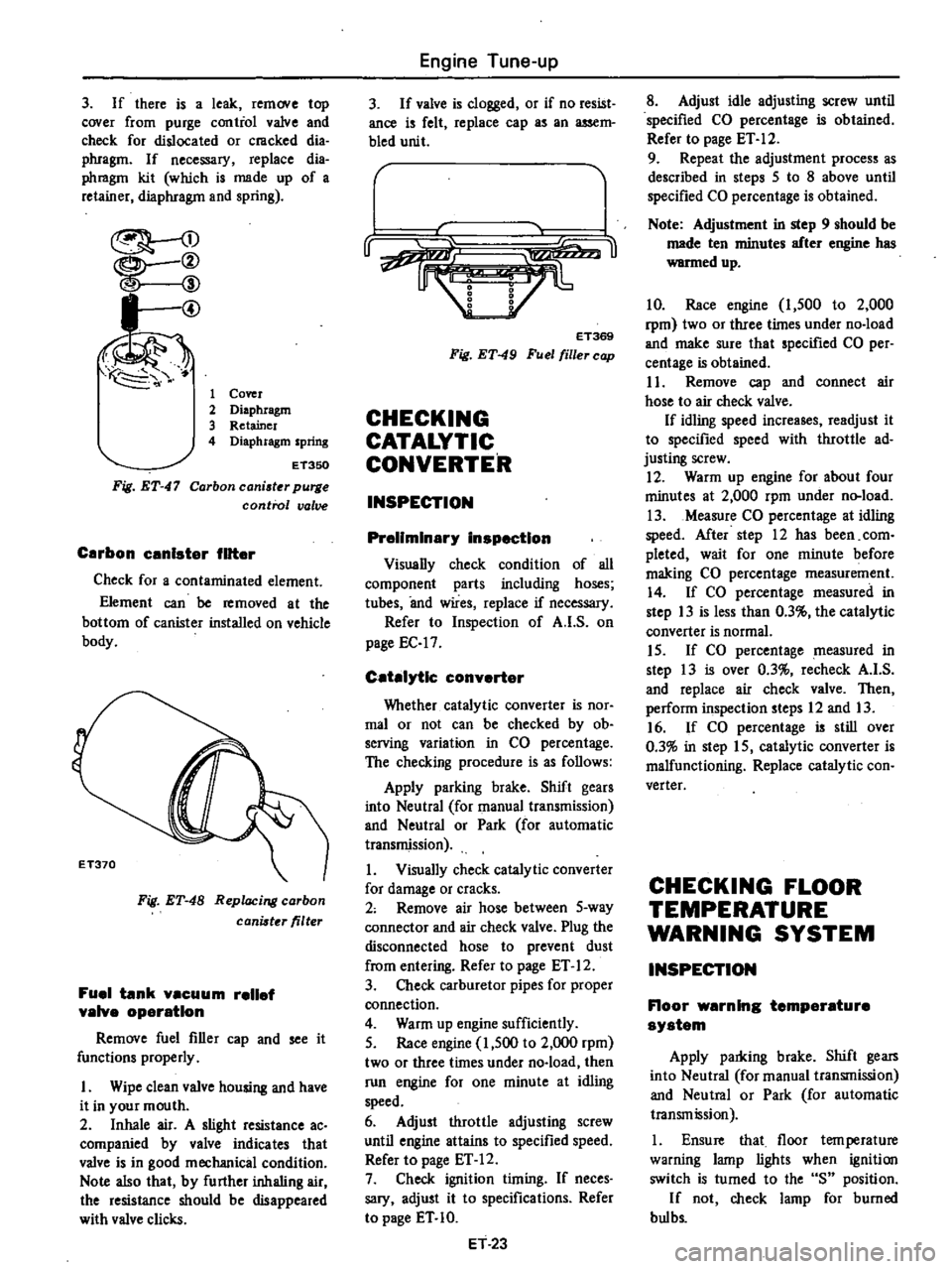
@
1
Cover
2
Diaphragm
3
Retainer
4
Diaphragm
spring
Fig
ET
47
ET350
Carbon
caniater
purge
control
valve
Carbon
unlster
filter
Check
for
a
contaminated
element
Element
can
be
removed
at
the
bottom
of
canister
installed
on
vehicle
body
Fig
ET
48
Replacing
carbon
canister
filter
Fuel
tank
vacuum
relief
valve
operation
Remove
fuel
filler
cap
and
see
it
functions
properly
I
Wipe
clean
valve
housing
and
have
it
in
your
mouth
2
Inhale
air
A
slight
resistance
ac
companied
by
valve
indicates
that
valve
is
in
good
mechanical
condition
Note
also
that
by
further
inhaling
air
the
resistance
should
be
disappeared
with
valve
clicks
Engine
Tune
up
3
If
valve
is
clogged
or
if
no
resist
ance
is
felt
replace
cap
as
an
assem
bled
unit
r
u
ET369
Fig
ET
49
Fuel
filler
cap
CHECKING
CATALYTIC
CONVERTER
INSPECTION
Preliminary
inspection
Visually
check
condition
of
all
component
parts
including
hoses
tubes
and
wires
replace
if
necessary
Refer
to
Inspection
of
A
I
S
on
page
EC
17
Catalytic
converter
Whether
catalytic
converter
is
nOf
mal
or
not
can
be
checked
by
ob
serving
variation
in
CO
percentage
The
checking
procedure
is
as
follows
Apply
parking
brake
Shift
gears
into
Neutral
for
manual
transmission
and
Neutral
or
Park
for
automatic
transmission
1
Visually
check
catalytic
converter
for
damage
or
cracks
2
Remove
air
hose
between
5
way
connector
and
air
check
valve
Plug
the
disconnected
hose
to
prevent
dust
from
entering
Refer
to
page
ET
12
3
Check
carburetor
pipes
for
proper
connection
4
Warm
up
engine
sufficiently
5
Race
engine
1
500
to
2
000
rpm
two
or
three
times
under
no
load
then
run
engine
for
one
minute
at
idling
speed
6
Adjust
throttle
adjusting
screw
until
engine
attains
to
specified
speed
Refer
to
page
ET
12
7
Check
ignition
timing
If
neces
sary
adjust
it
to
specifications
Refer
to
page
ET
10
ET
23
8
Adjust
idle
adjusting
screw
until
specified
CO
percentage
is
obtained
Refer
to
page
ET
12
9
Repeat
the
adjustment
process
as
described
in
steps
5
to
8
above
until
specified
CO
percentage
is
obtained
Note
Adjustment
in
step
9
should
be
made
ten
minutes
after
engine
has
warmed
up
10
Race
engine
1
500
to
2
000
rpm
two
or
three
times
under
no
load
and
make
sure
that
specified
CO
per
centage
is
obtained
I
1
Remove
cap
and
connect
air
hose
to
air
check
valve
If
idling
speed
increases
readjust
it
to
specified
speed
with
throttle
ad
justing
screw
12
Warm
up
engine
for
about
four
minutes
at
2
000
rpm
under
n
load
13
Measure
CO
percentage
at
idling
speed
After
step
12
has
been
com
pleted
wait
for
one
minute
before
making
CO
percentage
measurement
14
If
CO
percentage
measured
in
step
13
is
less
than
0
3
the
catalylic
converter
is
normal
15
If
CO
percentage
measured
in
step
13
is
over
0
3
recheck
A
I
S
and
replace
air
check
valve
Then
perform
inspection
steps
12
and
13
16
If
CO
percentage
is
still
over
0
3
in
step
15
catalytic
converter
is
malfunctioning
Replace
catalytic
con
verter
CHECKING
FLOOR
TEMPERATURE
WARNING
SYSTEM
INSPECTION
Floor
warning
temperature
system
Apply
parldng
brake
Shift
gears
into
Neutral
for
manual
transmission
and
Neutral
or
Park
for
automatic
transmission
1
Ensure
that
floor
tern
perature
warning
lamp
lights
when
ignition
switch
is
turned
to
the
S
position
If
not
check
lamp
for
burned
bul
bs
Page 116 of 537
ELECTRIC
AUTOMATIC
CHOKE
An
electric
heater
wanns
a
bi
metal
interconnected
to
the
choke
valve
and
controls
the
position
of
choke
valve
and
throttle
valve
in
accordance
with
the
time
elapsed
the
warm
up
condi
tion
of
the
engine
and
the
outside
ambient
temperature
When
outside
ambient
temperature
is
above
operating
temperature
the
automatic
choke
control
serves
to
fur
ther
reduce
exhaust
gasemission
during
warm
up
by
automatically
selecting
one
of
the
two
choke
opera
tion
modes
fast
acting
or
slow
acting
Slow
acting
choke
operation
When
ambient
temperature
is
low
electric
current
flows
through
the
automatic
choke
relay
to
the
P
T
C
heater
A
and
gradually
warms
the
bi
metal
This
causes
the
choke
valve
to
open
slowly
Fast
acting
choke
operation
When
ambient
temperature
is
high
the
bi
metal
switch
is
in
on
This
causes
electric
current
to
flow
through
the
automatic
choke
relay
to
the
P
T
C
heater
A
and
heater
B
result
ing
in
quick
opening
of
the
choke
valve
r
@@
r
@
Engine
Fuel
The
construction
and
function
of
each
part
of
this
carburetor
are
as
follows
l
Bi
metal
and
heater
in
choke
cover
Electric
current
flows
through
the
ttea
r
as
t
le
engine
tl
1
SI
nd
war
the
bi
metal
The
deflection
of
the
bi
metal
is
transmitted
to
the
choke
valve
through
the
choke
yalve
lever
2
Fast
idle
cam
The
fast
idle
cam
determines
the
opening
of
the
throttle
valve
so
that
the
proper
amount
of
mixture
cor
responding
to
the
opening
of
the
choke
valve
will
be
obtained
The
opening
of
the
choke
valve
is
depend
ent
upon
the
warm
up
condition
of
the
engine
3
Fast
idle
adjusting
screw
This
screw
adjusts
the
opening
of
the
throttle
valve
of
the
fast
idle
earn
4
U
nloader
When
accelerating
the
engine
during
the
warm
up
period
that
is
before
the
choke
valve
opens
sufficiently
this
unloader
forces
the
choke
valve
open
a
liUle
so
as
to
obtain
an
adequate
air
fuel
mixture
5
Vacuum
diaphragm
After
the
enginThas
been
started
by
cranking
this
diaphragm
forces
the
choke
valve
open
to
the
predetermined
extent
so
as
to
provide
the
proper
air
fuel
ratio
6
Bi
metal
case
index
mark
The
bi
metal
case
index
mark
is
used
for
setting
the
moment
of
the
D
Il
EF232
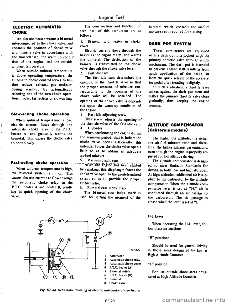
1
Alternator
2
Automatic
choke
relay
3
Automatic
choke
cover
4
P
T
C
heater
A
5
Bi
metal
switch
6
P
T
C
heater
B
7
Bi
metal
8
Choke
valve
Fig
EF
33
Schematic
drawing
of
electric
automatic
choke
heater
EF
20
bi
metal
which
controls
the
air
fuel
mixture
ratio
required
for
starting
DASH
POT
SYSTEM
These
carburetors
are
equipped
with
a
dash
pot
interl
ked
wi
h
the
primary
throttle
valve
through
a
link
mechanism
The
dash
pot
is
intended
to
prevent
engine
stall
resulting
from
quick
application
of
the
brake
or
from
the
quick
release
of
the
accele
ra
tor
pedal
after
treading
it
slightly
In
such
a
situation
a
throttle
lever
strikes
against
the
dash
pot
stem
and
makes
the
primary
throttle
valve
close
gradually
thus
keeping
the
engine
running
ALTITUDE
COMPENSATOR
California
models
The
higher
the
altitude
the
richer
the
air
fuel
mixture
ratio
and
there
fore
the
higher
exhaust
gas
emissions
even
though
the
engine
is
properly
ad
justed
for
low
altitude
driving
The
altitude
compensator
is
design
ed
to
meet
EiiriSSion
S13ndards
for
driving
in
both
low
and
high
altitudes
At
high
altitudes
additional
air
is
sup
plied
to
the
carburetor
by
the
altitude
compensator
When
the
altitude
com
pensator
lever
is
set
at
H
air
is
conducted
through
an
air
passage
to
the
carburetor
The
air
passage
is
closed
when
the
lever
is
set
at
L
H
L
Lever
When
operating
the
H
L
lever
fol
low
these
instructions
H
position
Should
be
used
for
general
driving
in
those
areas
designated
by
law
as
High
Altitude
Counties
L
position
For
use
outside
those
areas
desig
nated
as
High
Altitude
Counties
Page 160 of 537
REMOVAL
AND
INSPECTION
Removal
and
inspection
can
be
done
as
follows
Removal
Catalytic
converter
1
Apply
parking
brake
2
Place
wheel
lock
under
each
tire
3
Jack
up
the
vehicle
4
Remove
lower
shelter
of
catalytic
converter
5
Dismount
catalytic
converter
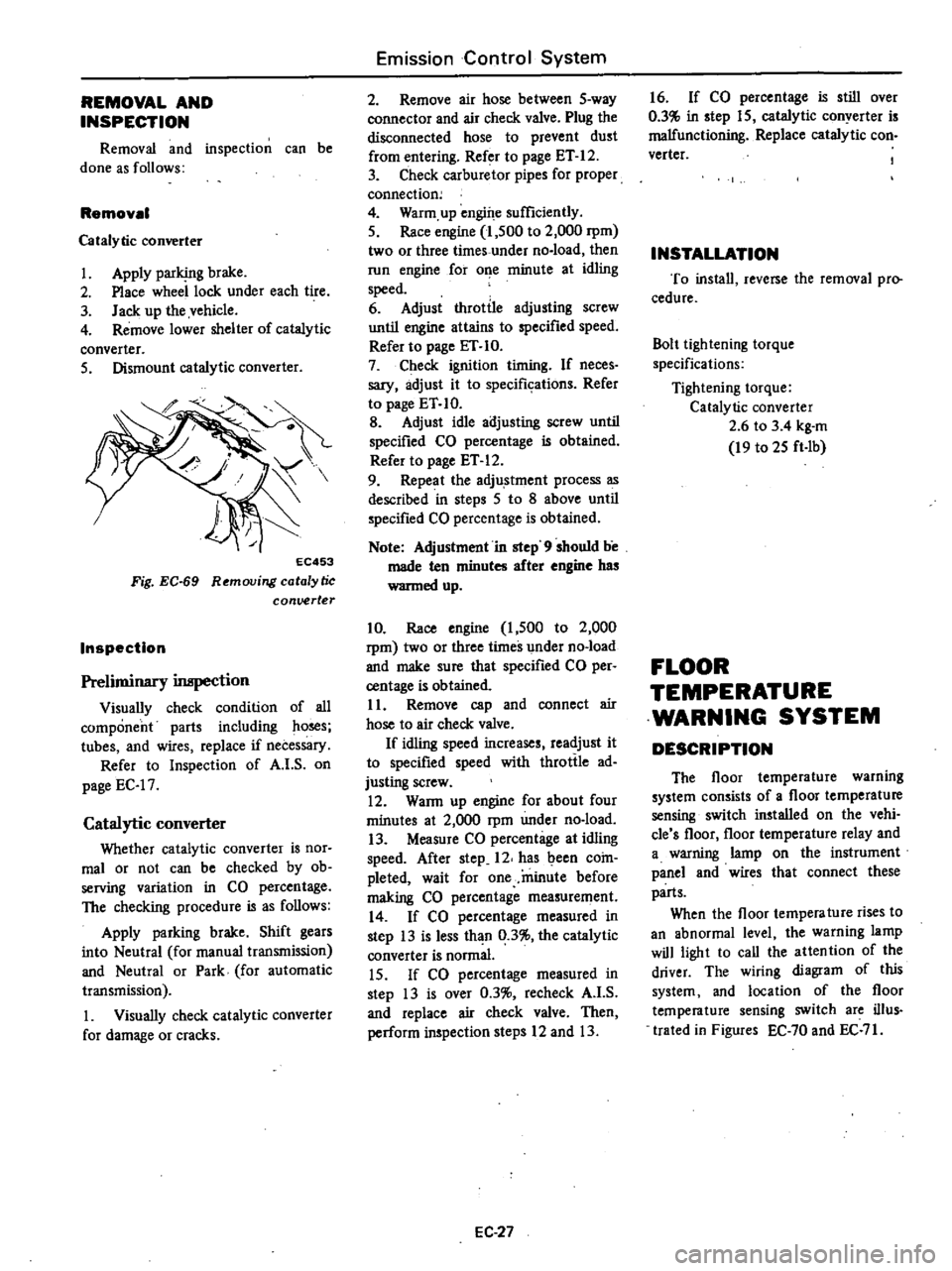
EC453
Fig
EC
69
Removing
catalytic
conuerter
Inspection
Preliminary
inspection
Visually
check
condition
of
all
component
parts
including
ho
s
tubes
and
wires
replace
if
necessary
Refer
to
Inspection
of
A
I
S
on
page
EC
17
Catalytic
converter
Whether
catalytic
converter
is
nor
mal
or
not
can
be
checked
by
ob
serving
variation
in
CO
percentage
The
checking
procedure
is
as
follows
Apply
parking
brake
Shift
gears
into
Neutral
for
manual
transmission
and
Neutral
or
Park
for
automatic
transmission
1
Visually
check
catalytic
converter
for
damage
or
cracks
Emission
Control
System
2
Remove
air
hose
between
5
way
connector
and
air
check
valve
Plug
the
disconnected
hose
to
prevent
dust
from
entering
Refer
to
page
ET
12
3
Check
carburetor
pipes
for
proper
connection
4
Warm
up
engine
sufficiently
5
Race
engine
1
500
to
2
000
rpm
two
or
three
times
under
no
load
then
run
engine
for
o
e
minute
at
idling
speed
6
Adjust
throttle
adjusting
screw
until
engine
attains
to
specified
speed
Refer
to
page
ET
10
7
Check
ignition
timing
If
neces
sary
adjust
it
to
specifkations
Refer
to
page
ET
10
B
Adjust
idle
adjusting
screw
until
specified
CO
percentage
is
obtained
Refer
to
page
ET
12
9
Repeat
the
adju
stment
process
as
described
in
steps
5
to
8
above
until
specified
CO
percentage
is
obtained
Note
Adjustment
in
step
9
should
be
made
ten
minutes
after
engine
has
wanned
up
10
Race
engine
1
500
to
2
000
rpm
two
or
three
times
under
no
load
and
make
sure
that
specified
CO
per
centage
is
obtained
11
Remove
cap
and
connect
air
hose
to
air
check
valve
If
idling
speed
increases
readjust
it
to
specified
speed
with
throttle
ad
justing
screw
12
WaRn
up
engine
for
about
four
minutes
at
2
000
rpm
under
no
load
13
Measure
CO
percentage
at
idling
speed
After
step
12
has
been
coin
pleted
wait
for
one
minute
before
making
CO
percentage
measurement
14
If
CO
percentage
measured
in
step
13
is
less
than
0
3
the
catalytic
converter
is
normal
15
If
CO
percentage
measured
in
step
13
is
over
0
3
recheck
A
I
S
and
replace
air
check
valve
Then
perform
inspection
steps
12
and
13
EC
27
16
If
CO
percentage
is
still
over
0
3
in
step
15
catalytic
conyerter
is
malfunctioning
Replace
catalytic
con
verter
INSTALLATION
To
install
reverse
the
removal
pro
cedure
Bolt
lightening
torque
specifications
Tightening
torque
Catalytic
converter
2
6
to
3
4
kg
m
19
to
25
ft
Ib
FLOOR
TEMPERATURE
WARNING
SYSTEM
DESCRIPTION
The
floor
temperature
warning
system
consists
of
a
floor
temperature
sensing
switch
installed
on
the
vehi
cle
s
floor
floor
temperature
relay
and
a
warning
lamp
on
the
instrument
panel
and
wires
that
connect
these
parts
When
the
floor
tempera
ture
rises
to
an
abnormal
level
the
warning
lamp
will
light
to
call
the
attention
of
the
driver
The
wiring
diagram
of
this
system
and
location
of
the
floor
temperature
sensing
switch
are
ilIus
trated
in
Figures
EC
70
and
EC
71
Page 162 of 537
Floor
temparature
warning
lamp
Refer
to
Figure
EC
74
for
the
loca
tion
of
this
part
L
1t
1
RAt
Fig
EC
74
Location
of
floor
temperature
warning
lamp
INSTALLATION
To
install
reverse
the
order
of
rem
ovaL
INSPECTION
Floor
warning
temperature
system
Apply
parking
brake
Shift
gears
into
Neutral
foI
manual
transmission
and
Neutral
or
Park
for
automatic
transmission
1
Ensure
that
floor
temperature
warning
lamp
lights
when
ignition
switch
is
iumed
to
the
S
position
If
not
check
lamp
for
burned
bulbs
Replace
bulb
if
bulb
is
burned
out
If
bulb
is
not
burned
trace
wire
s
back
to
ignition
switch
Repair
or
replace
if
necessary
2
Be
sure
that
floor
temperature
is
cool
below
800C
1760Fj
before
carrying
out
the
following
procedure
I
Remove
rearseat
2
Ignition
switch
is
turned
to
the
IG
position
3
Ensure
that
floor
temperature
warning
lamp
goes
out
4
Heat
surrounding
areas
of
floor
temperature
sensing
switch
with
a
proper
heater
to
ensure
that
floor
temperature
warning
lamp
glows
when
floor
is
heated
to
the
specifications
as
shown
in
the
table
below
Emission
Control
System
Temperature
sensing
switch
Contact
close
Temperature
warning
lamp
Off
Contact
open
On
Note
Avoid
heating
floor
tempera
ture
sensing
switch
directly
If
lamp
does
not
glow
check
floor
temperature
sensing
switch
connector
for
continuity
with
a
circuit
tester
If
continuity
should
exist
after
heated
surrounding
areas
of
floor
tem
perature
sensing
switch
replace
tem
perature
sensing
switch
If
con
tinuity
does
not
exist
trace
the
wiring
back
to
relay
or
check
the
following
step
3
Repair
or
replace
wire
s
if
necessary
Note
The
floor
temperature
sensing
switch
may
be
heated
through
the
floor
by
a
proper
heater
3
Turn
ignition
switch
to
the
IG
position
and
disconnect
floor
temper
ature
sensing
connector
The
lamp
should
remain
on
If
not
check
floor
temperature
relay
for
continuity
with
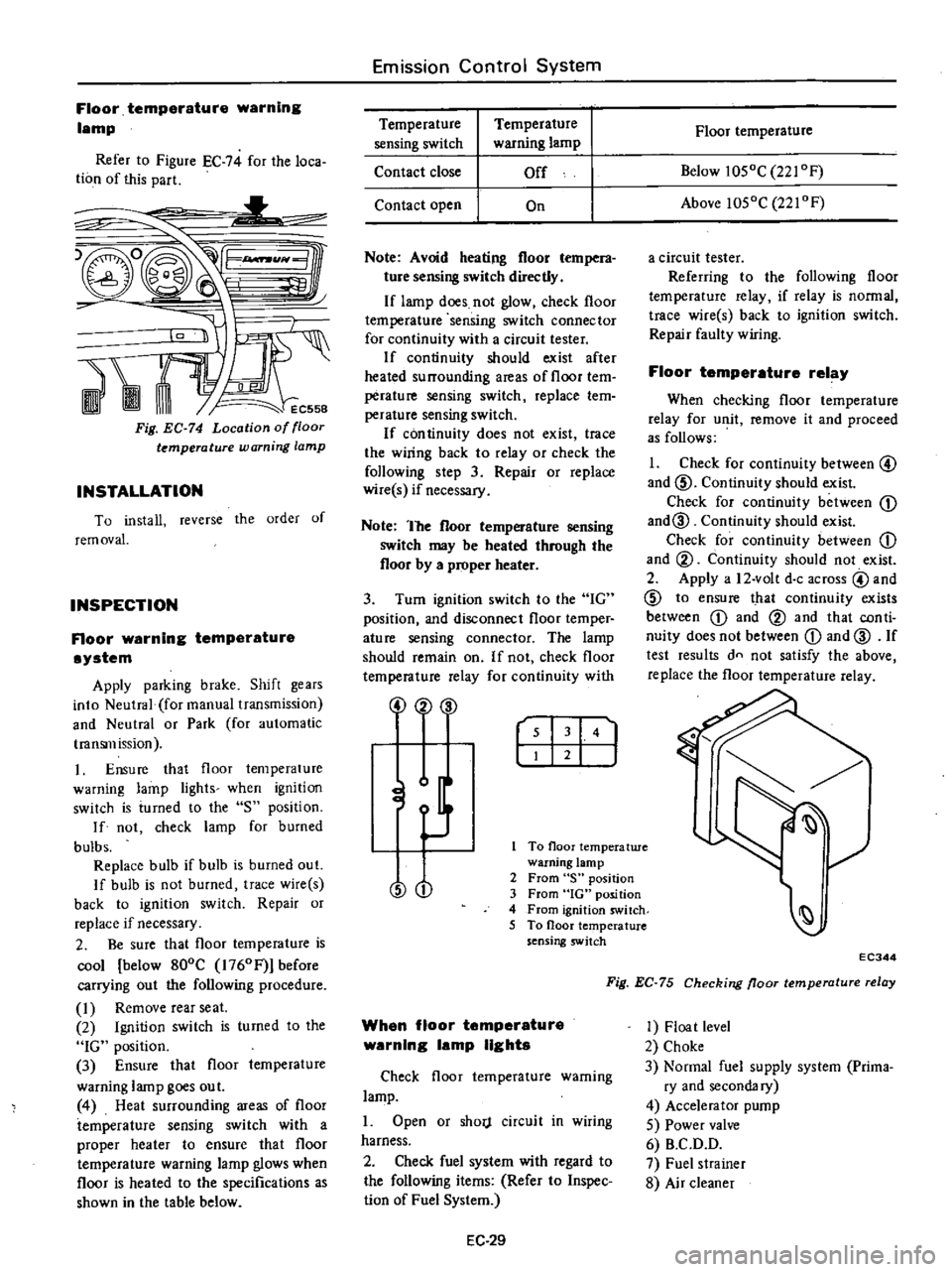
2
00
r
I
141
J
To
floor
temperatwe
warning
lamp
2
From
S
position
3
From
IG
position
4
From
ignition
switch
5
To
floor
temperature
sensing
switch
O
When
floor
temperature
warning
lamp
lights
Check
floor
temperature
warning
lamp
1
Open
or
shorj
circuit
in
wiring
harness
2
Check
fuel
system
with
regard
to
the
following
items
Refer
to
Inspec
lion
of
Fuel
System
EC
29
Floor
temperature
Below
1050C
221
OF
Above
1050C
221
OF
a
circuit
tester
Referring
to
the
following
floor
temperature
relay
if
relay
is
normal
trace
wire
s
back
to
ignition
switch
Repair
faulty
wiring
Floor
temperature
relay
When
checking
floor
temperature
relay
for
unit
remove
it
and
proceed
as
follows
1
Check
for
continuity
between
@
and
ID
Continuity
should
exist
Check
for
continuity
between
CD
and@
Continuity
should
exist
Check
for
continuity
between
CD
and
@
Continuity
should
not
exist
2
Apply
a
12
volt
doc
across
@
and
ID
to
ensure
that
continuity
exists
between
CD
and
@
and
that
con
ti
nuity
does
not
between
CD
and
@
If
test
results
dn
not
satisfy
the
above
replace
the
floor
temperature
relay
EC344
Fig
EC
75
Checking
floor
temperature
relay
1
Float
level
2
Choke
3
Normal
fuel
supply
system
Prima
ry
and
secondary
4
Accelerator
pump
5
Power
valve
6
B
C
D
D
7
Fuel
strainer
8
Air
cleaner
Page 253 of 537
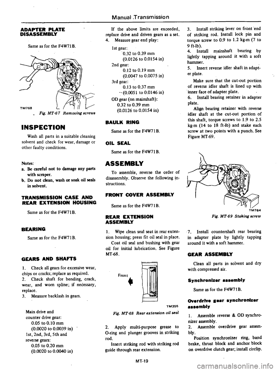
ADAPTER
PLATE
DISASSEMBLY
Same
as
for
the
F4W71
B
Fig
MT
67
Removing
screws
INSPECTION
Wash
all
parts
in
a
suitable
cleaning
solvent
and
check
for
wear
damage
or
other
faulty
conditions
Notes
a
Be
careful
not
to
damage
any
parts
with
scraper
b
Do
not
clean
wash
or
soak
oil
seals
in
solvent
TRANSMISSION
CASE
AND
REAR
EXTENSION
HOUSING
Same
as
for
the
F4W71
B
BEARING
Same
as
for
the
F4W7l
B
GEARS
AND
SHA
S
I
Check
all
gears
for
excessive
wear
chips
or
cracks
replace
as
required
2
Check
shaft
for
bending
crack
wear
and
worn
spline
if
necessary
replace
3
Measure
backlash
in
gears
Main
drive
and
counter
drive
gear
0
05
to
0
10
mm
0
0020
to
0
0039
in
1st
2nd
3rd
5th
and
reverse
gears
0
05
to
0
20
mm
0
0020
to
0
0040
in
Manual
Transmission
If
the
above
limits
are
exceeded
replace
drive
and
driven
gears
as
a
set
4
Measure
gear
end
play
1st
gear
0
32
to
0
39
mm
0
0126
to
0
0154
in
2nd
gear
0
12
to
0
19
mm
0
0047
to
0
0075
in
3rd
gear
0
13
to
0
37
mm
0
0051
to
0
0146
in
OD
gear
on
mainshaft
0
32
to
0
39
mm
0
0126
to
0
0154
in
BAULK
RING
Same
as
for
the
F4W7IB
OIL
SEAL
Same
as
for
the
F4W71
B
ASSEMBLY
To
assemble
reverse
the
order
of
disassembly
Observe
the
following
in
structions
FRONT
COVER
ASSEMBLY
Same
as
for
the
F4W7l
B
REAR
EXTENSION
ASSEMBLY
I
Wipe
clean
seal
seat
in
rear
exten
sion
housing
press
fit
oil
seal
in
place
Coat
oil
seal
and
bushing
with
gear
oil
for
initial
lubrication
See
Figure
MT
68
Front
r
I
TM355
Fig
MT
68
R
ar
extemion
oil
sea
2
Apply
multi
purpose
grease
to
O
ring
and
plunger
grooves
in
striking
rod
Insert
striking
rod
with
striking
rod
guide
through
rear
extension
MT19
3
Install
striking
lever
on
front
end
of
striking
rod
Install
lock
pin
and
torque
screw
to
0
9
to
1
2
kg
m
7
to
9
ft
lb
4
Install
filainshaft
bearing
by
lightly
tapping
around
it
with
a
soft
hammer
5
Insert
reverse
idler
shaft
in
adapt
er
plate
Make
sure
that
the
cut
out
portion
of
reverse
idler
shaft
is
lined
up
with
inner
face
of
adapter
plate
6
Install
bearing
retainer
in
adapter
plate
Align
bearing
retainer
with
reverse
idler
shaft
at
the
cut
out
portion
of
this
shaft
torque
screws
to
1
9
to
2
5
kg
m
14
to
18
ft
lb
and
stake
each
screw
at
two
points
with
a
punch
See
Figure
MT
69
TM764
Fig
MT
69
Stahing
screw
7
Install
countershaft
rear
bearing
in
adapter
plate
by
lightly
tapping
around
it
with
a
soft
hammer
GEAR
ASSEMBLY
Clean
all
parts
in
solvent
and
dry
with
compressed
air
Synchronlz
r
embly
Same
as
for
the
F4W71
B
Ov
rdrlve
r
ynchronlz
r
mbly
I
Assemble
reverse
OD
synchro
nizer
assembly
2
Assemble
overdrive
gear
assem
bly
Position
synchronizer
ring
band
brake
thrust
block
and
anchor
block
on
overdrive
clutch
gear
install
circlip
Page 267 of 537
The
control
valve
assembly
consists
of
the
following
valves
See
Figure
AT
20
I
Pressure
regulator
valve
PRV
2
Manual
valve
MNV
3
I
st
2nd
shift
valve
FSV
4
2nd
3rd
shift
valve
SSV
5
Pressure
modifier
valve
PMV
6
Vacuum
throttle
valve
VTV
7
Throttle
back
up
valve
TBV
8
Solenoid
downshift
valve
SDV
9
Second
lock
valve
SL
V
10
2nd
3rd
timing
valve
TMV
Pressure
regulator
valve
PRV
The
pressure
regulator
valve
re
ceives
valve
spring
force
force
from
the
plug
created
by
the
throttle
pres
sure
16
and
line
pressure
7
and
force
of
the
throttle
pressure
18
With
the
interaction
of
those
forces
the
PRY
regulates
the
line
pressure
7
to
that
most
suitable
for
individual
driving
conditions
The
oil
from
the
oil
pump
is
ap
plied
to
the
ring
shaped
area
through
orifice
20
As
a
result
the
PRV
is
depressed
downward
and
moves
from
port
7
up
to
such
extent
that
the
space
to
the
next
drain
port
marked
with
X
in
Figure
AT
10
opens
slightly
Thus
the
line
pressure
7
is
balanced
with
the
spring
force
there
by
balancing
the
PRV
In
this
opera
tion
Ihe
space
from
port
7
to
the
subsequent
converter
oil
pressure
14
circuit
has
also
been
opened
As
a
result
the
converter
is
filled
with
pressurized
oil
in
circuit
14
and
this
oil
is
further
used
for
lubrication
of
the
rear
unit
Moreover
part
of
the
oil
is
branched
and
used
for
lubrication
of
the
front
unit
for
the
front
and
rear
clutches
When
Ihe
accelerator
pedal
is
de
presscd
the
throttle
pressure
16
in
creases
as
described
in
the
preceding
paragraph
oil
pressure
is
applied
to
the
plug
through
orifice
21
and
this
pressure
is
added
to
the
spring
force
As
a
result
the
PRV
is
contrarily
forced
upward
space
to
the
drain
port
is
reduced
and
Ihe
line
pressure
7
increases
Automatic
Transmission
11
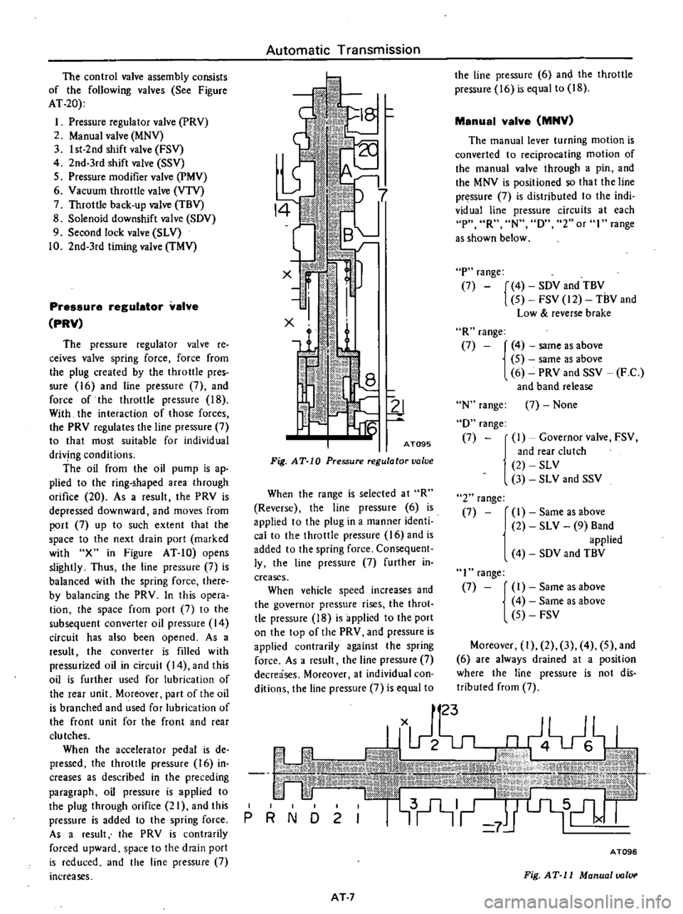
AT095
Fig
AT
10
Pressure
regulator
ualue
When
the
range
is
selected
at
R
Reverse
the
line
pressure
6
is
applied
10
the
plug
in
a
manner
identi
caito
the
throttle
pressure
16
and
is
added
10
the
spring
force
Consequent
ly
the
line
pressure
7
further
in
creases
When
vehicle
speed
increases
and
the
governor
pressure
rises
the
theot
tle
pressure
18
is
applied
to
the
port
on
the
top
of
the
PRV
and
pressure
is
applied
contrarily
against
the
spring
force
As
a
result
the
line
pressure
7
decreases
Moreover
at
individual
con
ditions
the
line
pressure
7
is
equal
to
the
line
pressure
6
and
the
throttle
pressure
16
is
equal
to
18
Manual
valve
MNV
The
manual
lever
turning
motion
is
converted
to
reciprocating
motion
of
the
manual
valve
through
a
pin
and
the
MNV
is
positioned
so
that
the
line
pressure
7
is
distributed
to
the
indi
vidual
line
pressure
circuits
at
each
P
R
N
D
2
or
I
range
as
shown
below
P
range
7
4
SDV
and
TBV
5
FSV
12
TBV
and
Low
reverse
brake
R
range
7
4
same
as
above
5
same
as
above
6
PRY
and
SSV
F
C
and
band
release
N
range
D
range
7
7
None
I
Governor
valve
FSV
and
rear
clutch
2
SLY
3
SL
V
and
SSV
2
range
7
I
Same
as
above
2
SL
V
9
Band
applied
4
SDV
and
TBV
I
range
7
I
Same
as
above
4
Same
as
above
5
FSV
Moreover
1
2
3
4
5
and
6
are
always
drained
at
a
position
where
the
line
pressure
is
not
dis
tributed
from
7
u
JJX
g4Vhl
dIillillt
1
dlMIi
W
ld
IiIb
It
i
B
J
jd
l
tJj
fitMi
td
j
L@
x
x
j
j
P
R
N
17
l
AT7
AT096
Fig
AT
11
Manual
ualvp
Page 298 of 537
Starter
should
be
brought
into
op
eration
only
when
selector
lever
is
in
P
and
N
positions
it
should
not
be
started
when
lever
is
in
D
2
I
and
R
positions
Back
up
lamp
should
also
light
when
selector
lever
is
placed
in
R
position
S
After
converter
is
installed
rotate
10
Check
level
of
oil
in
transmis
crankshaft
several
turns
and
check
to
be
sure
that
transmission
rotates
freely
sion
For
detailed
procedure
see
page
AT48
without
binding
6
Pour
recommended
automatic
II
Move
selector
lever
through
aU
positions
to
be
sure
that
transmission
transmission
fluid
up
to
correct
level
operates
correctly
through
oil
charge
pipe
verter
to
transmission
measure
dis
With
hand
brake
applied
rotate
tan
A
to
be
certain
that
they
are
7
Connect
manual
lever
to
shift
engine
at
idling
Without
disturbing
correctly
mbi
d
S
F
rod
Opeiationsliould
oecaTrie
f
bue
the
above
sclUng
ffiovTSelector
lever
AT
50
with
manual
and
selector
levers
in
through
N
to
D
to
2
to
I
Distance
A
N
and
to
R
A
slight
shock
should
be
More
than
21
5
mm
0
846
in
8
Connect
inhibitor
switch
wires
felt
by
hand
gripping
selector
each
time
transmission
is
shifted
Automatic
Transmission
4
Bolt
converter
to
drive
plate
Note
Align
chalk
marks
painted
a
cross
both
parts
during
disas
sembling
processes
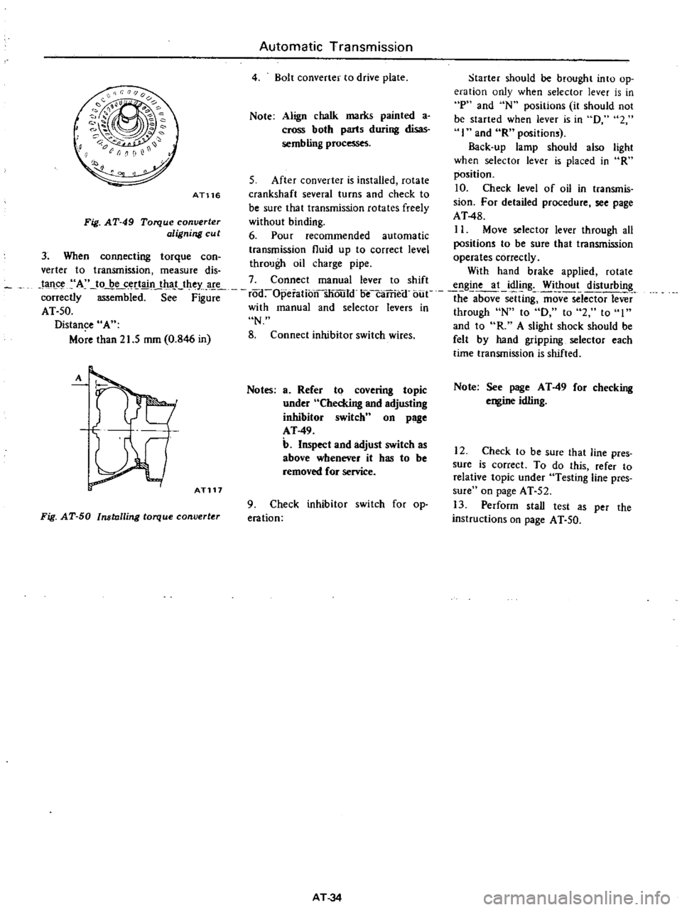
AT116
Fig
AT
49
Torque
converter
aligning
cu
t
3
When
connecting
torque
can
A
ATl17
Notes
a
Refer
to
covering
topic
under
Checking
and
adjusting
inhibitor
switch
n
on
page
AT
49
b
Inspect
and
adjust
switch
as
above
whenever
it
has
to
be
removed
for
service
Fig
AT
50
Installing
torque
converter
9
Check
inhibitor
switch
for
op
eration
AT
34
Note
See
page
AT
49
for
checking
engine
idling
12
Check
to
be
sure
that
line
pres
sure
is
correct
To
do
this
refer
to
relative
topic
under
Testing
line
pres
sure
on
page
AT
52
13
Perform
stall
test
as
per
the
instructions
on
page
AT
50
Page 307 of 537
Automatic
Transmission
i
r
11
I
@
@
j
A
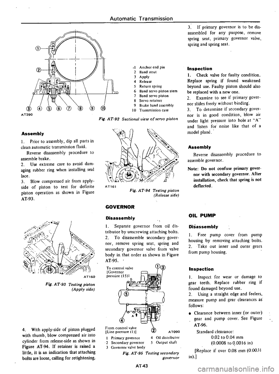
T290
Assembly
I
Prior
to
assembly
dip
all
parts
in
clean
automatic
transmission
fluid
Reverse
disassembly
procedure
to
assemble
brake
2
Use
extreme
care
to
avoid
dam
aging
rubber
ring
when
installing
seal
lace
3
Blow
compressed
air
from
apply
side
of
piston
to
test
for
definite
piston
operation
as
shown
in
Figure
AT
93
7
i
8
ror
1
1
r
c
f
f
A
J
II
1
0
c
r
1
1
I
@
L
O
j
0
n
iJ
fl
IV
I
AT160
Fig
AT
93
Testing
piston
Apply
side
4
With
apply
side
of
piston
plugged
with
thumb
blow
compressed
air
into
cylinder
from
release
side
as
shown
in
Figure
AT
94
If
retainer
is
raised
a
little
it
is
an
indication
that
attaching
bolts
are
loose
calling
for
retightening
1
Anchor
end
pin
2
Band
strut
3
Apply
4
Release
5
Return
spring
6
Band
servo
piston
stem
7
Band
servo
piston
8
Servo
retainer
9
Brake
band
assembly
10
Transmission
case
Fig
AT
92
Sectional
view
ofseruo
piston
7
o
i
J
1S
I
z
1
Y
i
1
t
9
c
fa
AT161
Fig
AT
94
Testing
piston
Release
side
GOVERNOR
Disassembly
I
Separate
governor
from
oil
dis
tributor
by
unscrewing
attaching
bolts
2
To
disassemble
secondary
gover
nor
remove
spring
seat
spring
and
secondary
governor
valve
from
valve
body
in
that
order
as
shown
in
Figure
AT
95
To
control
val
i
1
3
5MI
n
ID
r
Ii
I
4
From
control
valve
Line
pre
sure
I
I
A
TOgO
4
Oil
distributor
5
Output
shaft
I
Primary
governor
2
Secondary
governor
3
Governor
valve
body
Fig
AT
95
Testing
secondary
govemor
AT
43
3
If
primary
governor
is
to
be
dis
assembled
for
any
purpose
remove
spring
seat
primary
governor
valve
spring
and
spring
seat
Inspection
I
Check
valve
for
faulty
condition
Replace
spring
if
found
weakened
beyond
use
Faulty
piston
should
also
be
replaced
with
a
new
one
2
Examine
to
see
if
primary
gover
nor
slides
freely
without
binding
3
To
determine
if
secondary
gaver
nor
is
in
good
condition
blow
air
under
light
pressure
into
hole
at
A
and
listen
for
noise
like
that
of
a
model
plane
Assembly
Reverse
disassembly
procedure
to
assemble
governor
Note
Do
not
confuse
primary
gover
nor
with
secondary
governor
After
installation
check
that
spring
is
not
deflected
OIL
PUMP
Disassembly
I
Free
pump
cover
from
pump
housing
by
removing
attaching
bolts
2
Take
out
inner
and
outer
gears
from
pump
housing
Inspection
I
Inspect
for
wear
or
damage
to
gear
teeth
Replace
rubber
ring
if
found
damaged
beyond
use
2
Using
a
straight
edge
and
feelers
measure
pump
and
gear
clearances
as
follows
Clearance
between
inner
or
outer
gear
and
pump
cover
See
Figure
AT
96
Standard
clearance
0
02
to
0
04
mm
0
0008100
0016
in
Replace
if
over
0
08
mm
0
00
11
in
Page 314 of 537
Using
the
tester
check
the
two
black
yellow
BY
wires
from
the
in
hibitor
switch
in
the
ranges
N
and
I
and
the
tw
re
d
black
RBj
wir
s
in
the
range
R
for
continuity
Turn
range
select
lever
in
both
directions
from
each
lever
set
position
and
check
each
continuity
range
It
is
normal
if
the
electricity
is
on
while
the
lever
is
within
an
angle
of
about
30
on
both
sides
from
each
lever
set
line
How
ever
if
its
continl
ity
range
is
obvious
ly
unequal
on
both
sides
adjustment
is
required
If
any
malfunction
is
found
un
screw
the
fastening
nut
of
the
range
selector
lever
and
two
fastening
bolts
of
the
switch
body
and
then
remove
the
machine
screw
under
the
switch
body
Adjust
the
manual
shaft
correct
ly
to
the
position
N
by
means
of
the
selector
lever
When
the
slot
of
the
shaft
becomes
vertical
the
detent
works
to
position
the
shaft
correctly
with
a
clicking
sound
MSlVe
the
switch
slightly
asj
Je
so
that
the
screw
hole
will
be
aligned
with
the
pin
hole
of
the
internal
rotor
combined
with
the
manual
shaft
and
check
their
alignment
by
inserting
a
1
5
mm
0
059
in
diameter
pin
into
the
holes
If
the
alignment
is
correct
fasten
the
switch
body
with
the
bolts
pull
out
the
pin
tighten
up
the
screw
in
the
hole
and
fasten
the
selector
lever
as
before
Check
the
continuity
again
with
the
tester
If
the
malfunc
tion
still
remains
replace
the
inhibitor
switch
Chcck
whether
the
reverse
lamp
and
the
starter
motor
operate
normal
ly
in
these
ranges
If
Ihere
is
any
lrouble
first
check
the
linkage
If
no
fault
is
found
in
the
linkage
check
the
inhibitor
switch
Separate
the
manual
lever
from
Ihe
remote
control
selector
rod
and
turn
the
range
selcct
lever
to
N
Note
In
the
position
N
the
slot
of
the
manual
shaft
is
vertical
STALL
TEST
The
purpose
of
this
test
is
to
check
the
transmission
and
engine
for
trou
ble
by
measuring
the
maximum
num
bers
of
revolutions
of
the
engine
while
Automatic
Transmission
vehicle
is
held
in
a
stalled
condition
The
carburctor
is
in
full
throttle
opera
tion
with
the
selector
lever
in
ranges
f
2
and
I
respectively
Com
pare
the
measured
results
with
the
slandard
values
Components
to
be
tested
and
test
items
I
Clutches
brake
and
band
in
trans
mission
for
slipping
2
Torque
converter
for
proper
fune
tioning
3
Engine
for
overall
properly
STALL
TEST
PROCEDURES
Before
Icsting
c
heck
the
engine
oil
and
torque
converter
oil
warm
up
the
engine
cooling
water
to
suitable
tem
perature
by
running
at
1
200
rpm
with
the
selector
lever
in
the
range
P
for
several
minutes
Warm
up
the
torque
converter
oil
to
suitable
temperature
6010
1000C
140
to
2l20F
I
Mount
the
engine
tachometer
at
a
location
that
allows
good
visibility
fro
the
dri
er
s
seat
and
put
a
mark
on
specified
revolutions
on
the
meter
2
Secure
the
front
and
rear
wheels
with
chocks
and
apply
the
hand
brake
Be
sure
to
depress
the
brake
pedal
fumly
with
the
left
foot
before
de
pressing
the
accelerator
pedal
3
Throw
the
selector
lever
into
the
range
1
4
Slowly
depress
the
accelerator
pedal
until
the
throttle
valvc
is
fully
opened
Quickly
read
and
record
the
engine
revolution
when
the
engine
begins
to
rotate
steadily
and
then
release
the
accelerator
pedal
5
Shift
the
selector
lever
to
N
and
operate
the
engine
at
approxi
mately
1
200
rpm
for
more
than
one
minute
to
cool
down
the
torque
con
ver
ter
oil
and
coolant
6
Make
similar
stall
tests
in
ranges
2
I
and
RIO
Note
The
stall
test
operation
as
speci
f
d
in
item
4
should
be
I
l3de
wiihin
five
seconds
If
it
takes
too
long
the
oil
deteriorates
an
the
clutches
brake
and
band
are
ad
versely
affected
Sufficient
cooling
time
should
be
given
between
each
AT
5O
test
for
the
four
ranges
0
2
I
and
R
JUDGEMENT
High
stall
revolution
more
than
standard
revolution
If
the
engine
revolution
in
stall
condition
is
higher
than
the
standard
values
it
indicates
that
one
or
more
clutches
in
the
transmission
are
slipping
and
therefore
no
further
test
is
required
For
the
following
abnormalities
the
respective
causes
are
presumed
High
rpm
in
all
ranges
low
Iine
pressure
High
rpm
in
D
2
and
I
and
normal
rpm
in
R
Rear
clutch
slipping
High
rpm
in
0
and
normal
rpm
in
I
clutch
slipping
High
rpm
in
R
only
Front
clutch
or
low
and
reverse
brake
slipping
To
determine
which
is
slipping
front
clutch
or
low
and
reverse
brake
a
road
test
is
nceded
If
whilc
coasting
after
starting
with
the
lever
in
1
range
engine
braking
does
not
work
properly
the
low
and
reverse
brake
is
slipping
Otherwise
the
front
clutch
is
slipping
Slipping
of
the
band
brake
is
diffi
cult
to
ascertain
However
if
it
occurs
with
the
lever
in
2
range
engine
revolution
increases
Jp
to
thesarne
level
as
in
I
strange
It
is
impossible
to
check
it
in
the
stall
test
2
and
One
way
2
Standard
stall
revolution
If
the
engine
revolution
in
stall
condition
is
within
the
standard
values
the
control
elements
are
nor
mally
operating
in
the
ranges
0
2
I
and
R
Also
tIle
engine
and
one
way
clutch
of
the
torque
converter
are
normal
in
performance
and
operation
The
one
way
clutch
of
the
torque
converter
however
sometimes
sticks
This
is
determined
in
the
road
test
3
Lower
stall
revolution
than
stand
ard
revolution
If
the
engine
revolution
in
stall
condition
is
lower
than
the
standard
Page 352 of 537
The
design
of
the
front
suspension
adopts
the
independent
double
wishbone
type
suspension
used
the
torsion
bar
spring
Both
the
upper
and
lower
links
are
installed
on
the
bracket
which
is
welded
on
the
frame
A
1d
the
above
links
swing
to
allow
the
knuckle
spindle
to
move
freely
in
a
vertical
dimension
The
top
and
bottom
of
the
knuckle
spindle
support
are
connected
to
the
upper
link
through
rubber
bushing
and
to
the
lower
lick
through
screw
bushing
The
tension
rod
held
by
the
brack
ets
on
the
chassis
frame
and
lower
lick
wiih
rubber
bushings
bears
the
force
of
fore
and
aft
direction
The
front
end
of
the
torsion
bar
spring
is
installed
to
the
torque
arm
which
attaches
to
the
lower
link
The
opposite
end
is
installed
to
the
spring
anchor
that
secures
to
chassis
frame
firmly
The
both
ends
of
the
torsion
bar
spring
are
serrated
The
shock
absorber
is
double
action
telescopic
hydraulic
type
The
upper
stem
is
attached
to
the
bracket
of
the
chassis
frame
The
lower
insulated
bracket
is
bolted
to
the
lower
lick
The
bumper
rubber
secured
to
the
bracket
Of
the
frame
limits
the
verti
cal
motion
of
the
suspension
lick
The
knuckle
spindle
is
connecied
to
the
k
ufkle
spindle
arm
by
the
king
pin
The
king
pin
bushings
are
fitted
to
the
upper
and
lower
arm
portIOns
of
the
knuckle
spindle
and
seals
are
provided
at
the
portions
mentioned
to
keep
water
and
dirt
from
enteri
g
The
knuckle
arm
is
connected
to
the
lower
end
of
the
knuckle
spindle
to
transmit
ttLe
movement
of
the
steering
wheel
to
the
knuckle
spindle
The
wheel
hub
is
supported
by
two
taper
roller
bearings
on
the
knuckle
spindle
Tlie
brake
drum
and
wheel
are
secured
to
ihe
hub
by
the
hub
bolts
Front
Axle
Front
Suspension
FRONT
AXLE
REMOVAL
AND
INSTALLATION
Removal
I
Jack
up
and
support
vehicle
on
the
stands
at
the
frame
in
a
safe
manner
2
Remove
front
wheel
3
Re
ove
brake
hose
together
with
connector
from
wheel
cylinder
4
Remove
brake
drum
S
Remove
hub
cap
and
then
remove
cotter
pin
adjusting
cap
and
spindle
nut
from
knuckle
spindle
6
Remove
wheel
hub
outer
and
inner
wheel
bearings
bearing
washer
and
grease
seal
from
knuckle
spindle
7
Remove
brake
disc
assembly
from
the
flange
of
knuckle
spindle
8
Remove
knuckle
arm
from
knuckle
spindle
9
Remove
king
pin
lock
bolt
FA225
Fig
FA
R
mol1ing
king
pin
loch
nut
10
After
removing
air
breather
re
move
plug
from
the
top
of
king
pin
with
the
following
method
Drill
a
10
5
mm
0
413
in
diameter
hole
on
the
plug
thread
hole
with
a
tap
M
12
1
2S
screw
a
bolt
into
threaded
hole
and
pull
out
the
plug
II
Apply
drift
to
the
top
of
king
pin
and
drive
out
king
pin
along
with
lower
plug
12
Tap
spindle
with
a
soft
haJnmer
and
detach
it
from
knuckle
spindle
support
Take
care
not
io
drop
thrust
bearing
FA
3
FA226
Fig
FA
3
R
moving
knuckle
piridle
Installation
Install
front
axle
in
reverse
se
quence
to
removal
by
noting
the
fol
lowing
matters
Furthermore
when
installing
front
axle
lightly
coat
grease
to
sliding
parts
I
Insert
O
ring
on
the
lower
end
of
knuckle
spindle
support
Install
thrust
bearing
and
spindle
shim
together
with
knuckle
spindle
to
knuckle
spindle
support
In
this
operation
select
spindle
shims
to
obtain
the
specified
clearance
between
knuckle
spindle
and
knuckle
spindle
support
To
measure
the
Clear
ance
with
a
filler
gauge
jack
up
the
bottom
of
spindle
slightly
Standard
clearance
0
1
mOl
0
004
in
or
less
Note
Be
sure
to
iristsll
thrust
bearing
to
face
coverea
side
upward
2
Line
up
locking
bolt
hole
of
knuckle
spindle
support
with
the
notch
in
king
pin
and
secure
lock
bolt
Be
sure
to
check
killJckle
spindle
for
smooth
movement
Be
certain
to
move
knuckie
spindle
smoothly
and
reailjust
shim
if
necessary
In
addition
check
bushings
and
king
pin
as
required
3
Press
fit
plug
to
the
upper
of
knuckle
spindle
Then
install
lower
plug
to
the
lower
knuckle
spindle
Note
Make
sure
to
place
lower
plug
conectly
4
Secure
knuckle
arm
to
knuckle