fuel DODGE CARAVAN 2008 5.G Owners Manual
[x] Cancel search | Manufacturer: DODGE, Model Year: 2008, Model line: CARAVAN, Model: DODGE CARAVAN 2008 5.GPages: 531, PDF Size: 7.72 MB
Page 44 of 531
²There is a hold-open latch that is activated when the
sliding door is fully opened. This latch will keep your
sliding door open on any incline. To close the sliding
door after the hold-open latch is activated, you must
rock the inside handle forward or pull outward on the
outside handle.
Always make sure that the sliding door is fully latched
anytime the vehicle is in motion.
NOTE:The left side sliding door cannot be opened
while the fuel door is open. This feature operates only
when the sliding door is fully closed prior to opening the
fuel door.POWER SLIDING SIDE DOOR Ð IF EQUIPPED
The power sliding door may be opened manually or by
using the buttons on the Remote Keyless Entry (RKE)
transmitter.
Press the button on the transmitter twice within five
seconds, to open a power sliding door. When the door is
fully open, pressing the button twice within five seconds
a second time will close the door.
There are also power sliding side door switches located
on the trim panel just in front of the power sliding door
for the rear seat passengers. Pressing the switch once will
open the power sliding door. When the door is fully open
pressing the switch a second time will close the door.
42 THINGS TO KNOW BEFORE STARTING YOUR VEHICLE
Page 45 of 531
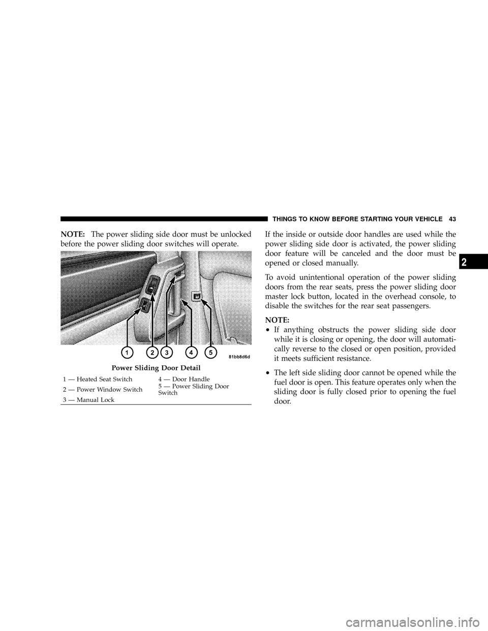
NOTE:The power sliding side door must be unlocked
before the power sliding door switches will operate.If the inside or outside door handles are used while the
power sliding side door is activated, the power sliding
door feature will be canceled and the door must be
opened or closed manually.
To avoid unintentional operation of the power sliding
doors from the rear seats, press the power sliding door
master lock button, located in the overhead console, to
disable the switches for the rear seat passengers.
NOTE:
²If anything obstructs the power sliding side door
while it is closing or opening, the door will automati-
cally reverse to the closed or open position, provided
it meets sufficient resistance.
²The left side sliding door cannot be opened while the
fuel door is open. This feature operates only when the
sliding door is fully closed prior to opening the fuel
door.Power Sliding Door Detail
1 Ð Heated Seat Switch 4 Ð Door Handle
2 Ð Power Window Switch5 Ð Power Sliding Door
Switch
3 Ð Manual LockTHINGS TO KNOW BEFORE STARTING YOUR VEHICLE 43
2
Page 76 of 531
Front and Side Impact Sensors
Impact Sensors trigger airbag deployment in front and
side impacts, and aid the ORC in determining appropri-
ate response to impact events. Additional sensors in the
ORC determine the level of airbag deployment and
provide verification.
Acceleration Sensors
Acceleration Sensors trigger airbag deployment based on
dramatic acceleration change of the vehicle.
Pressure Sensors
Pressure Sensors trigger airbag deployment based on
door cavity pressure changes.
Rollover Sensors
Rollover Sensors trigger airbag deployment in the event
of vehicle rollover and aid the ORC in deploying Side
Airbag Inflatable Curtains (SABIC) for rollover events.
Supplemental Side Airbag Inflatable Curtain
(SABIC) Ð If Equipped
The ORC deploys the SABIC during collision with other
vehicles and during collisions where the impact is con-
fined to a particular area of the vehicle Ð such as
collisions with poles, trees or similar objects.
It will deploy the SABIC only on the impact side of the
vehicle.
NOTE:The ORC does detect and protect for rollover
when equipped with SABIC airbags.
Enhanced Accident Response System
In the event of an impact causing airbag deployment, and
the vehicle communication network intact, and the
power intact, the Enhanced Accident Response System
performs the following functions:
²Cuts off fuel to the engine.
²Flashes hazard lights.
74 THINGS TO KNOW BEFORE STARTING YOUR VEHICLE
Page 96 of 531
Airbag Light
The light should come on and remain on for four seconds
as a bulb check when the ignition switch is first turned
ON. If the LED is not lit during starting and/or the light
stays on or comes ON while driving, have the system
checked by an authorized dealer.
Defroster
Check operation by selecting the defrost mode and place
the blower control on high speed. You should be able to
feel the air directed against the windshield.
NOTE:If the defroster is not working or you are unable
to feel air against the windshield in defrost mode, please
see your authorized dealer service center for repairs.
PERIODIC SAFETY CHECKS YOU SHOULD MAKE
OUTSIDE THE VEHICLE
Tires
Examine tires for excessive tread wear or uneven wear
patterns. Check for stones, nails, glass, or other objects
lodged in the tread. Inspect tread and sidewall for cuts or
cracks. Check wheel nuts for tightness, and tires (includ-
ing spare) for proper pressure.
Lights
Have someone observe the operation of exterior lights
while you work the controls. Check turn signal and high
beam indicator lights on the instrument panel.
Fluid Leaks
Check area under vehicle after overnight parking for fuel,
engine coolant, oil or other fluid leaks. Also, if gasoline
fumes are detected or fuel, power steering fluid, trans-
mission fluid or brake fluid leaks are suspected, the cause
should be located and corrected immediately.
94 THINGS TO KNOW BEFORE STARTING YOUR VEHICLE
Page 228 of 531
INSTRUMENT CLUSTER DESCRIPTIONS
1. Fuel Gauge
The pointer shows the level of fuel in the fuel tank when
the ignition switch is in the ON position.
2. Fuel Door Reminder
The arrow in this symbol is a reminder that the
Fuel Filler Door is located on the left side of the
vehicle.
3. Temperature Gauge
The temperature gauge shows engine coolant tempera-
ture. Any reading within the normal range indicates that
the engine cooling system is operating satisfactorily.The gauge pointer will likely indicate a higher tempera-
ture when driving in hot weather, up mountain grades,
or when towing a trailer. It should not be allowed to
exceed the upper limits of the normal operating range.
CAUTION!
Driving with a hot engine cooling system could
damage your vehicle. If temperature gauge reads
ªHª, pull over and stop the vehicle. Idle the vehicle
with the air conditioner turned off until the pointer
drops back into the normal range. If the pointer
remains on the ªHº, and you hear continuous chimes,
turn the engine off immediately, and call an autho-
rized dealer for service.
226 UNDERSTANDING YOUR INSTRUMENT PANEL
Page 232 of 531
replacement, be sure to keep a record of the reading
before and after the service so that the correct mileage can
be determined.
The trip odometer shows individual trip mileage. To
switch from odometer to trip odometer, press the Trip
Odometer button.
To reset a trip odometer, display the desired trip odom-
eter to be reset then push and hold the button until the
display resets (approximately two seconds).
12. PRNDL/Odometer Display Area
When the appropriate conditions exist, the following
odometer messages will display:
CHAngE OIL............... OilChange Required
CRUISE.....................Cruise Control On
door.............................Door Ajar
ESPOFF............................ ESPOffgATE..........................Lift Gate Ajar
gASCAP.......................Fuel Cap Fault
hood*............................Hood Ajar
noFUSE..........................Fuse Fault
LoCOOL........................ LowCoolant
LoWASH.................... LowWasher Fluid
NOTE:If your vehicle is equipped with an hood switch,
in the case of hood ajar, a warning message will be
displayed in either the PRNDL/Odometer display as
ªhoodº or ªHood Ajarº in the EVIC display.
NOTE:Some of the above warnings will be displayed in
the Compass Mini-Trip Computer / Electronic Vehicle
Information Center Display Area under the Speedometer.
CHAngE OIL
Your vehicle is equipped with an engine oil change
indicator system. The ªChange Oilº message will flash in
the instrument cluster odometer for approximately 12
230 UNDERSTANDING YOUR INSTRUMENT PANEL
Page 234 of 531
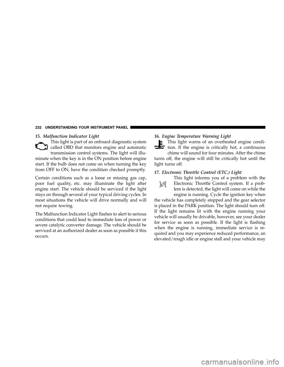
15. Malfunction Indicator Light
This light is part of an onboard diagnostic system
called OBD that monitors engine and automatic
transmission control systems. The light will illu-
minate when the key is in the ON position before engine
start. If the bulb does not come on when turning the key
from OFF to ON, have the condition checked promptly.
Certain conditions such as a loose or missing gas cap,
poor fuel quality, etc. may illuminate the light after
engine start. The vehicle should be serviced if the light
stays on through several of your typical driving cycles. In
most situations the vehicle will drive normally and will
not require towing.
The Malfunction Indicator Light flashes to alert to serious
conditions that could lead to immediate loss of power or
severe catalytic converter damage. The vehicle should be
serviced at an authorized dealer as soon as possible if this
occurs.16. Engine Temperature Warning Light
This light warns of an overheated engine condi-
tion. If the engine is critically hot, a continuous
chime will sound for four minutes. After the chime
turns off, the engine will still be critically hot until the
light turns off.
17. Electronic Throttle Control (ETC.) Light
This light informs you of a problem with the
Electronic Throttle Control system. If a prob-
lem is detected, the light will come on while the
engine is running. Cycle the ignition key when
the vehicle has completely stopped and the gear selector
is placed in the PARK position. The light should turn off.
If the light remains lit with the engine running your
vehicle will usually be drivable, however, see your dealer
for service as soon as possible. If the light is flashing
when the engine is running, immediate service is re-
quired and you may experience reduced performance, an
elevated/rough idle or engine stall and your vehicle may
232 UNDERSTANDING YOUR INSTRUMENT PANEL
Page 236 of 531
during starting, stays on, or turns on while driving, have
the system inspected by an authorized dealer as soon as
possible.
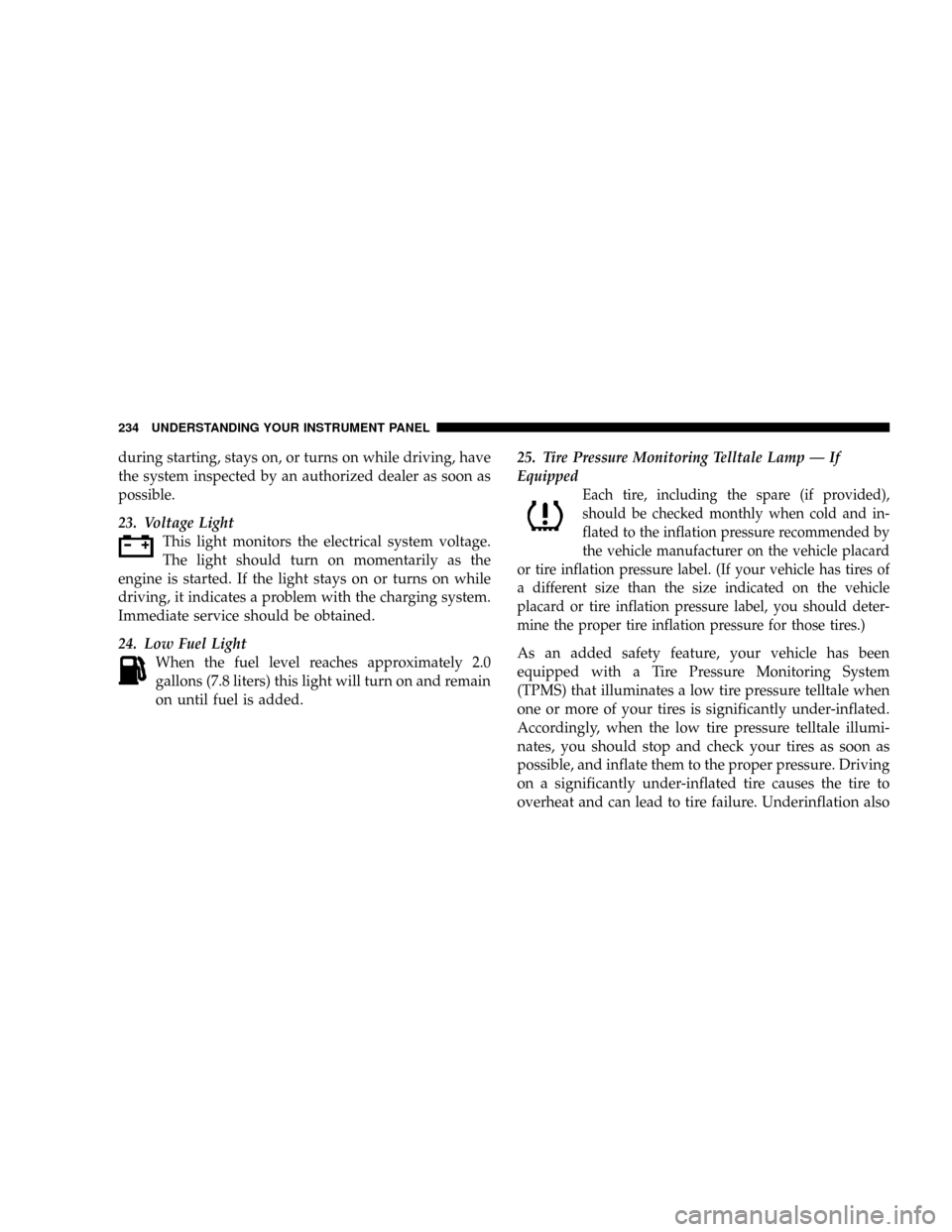
23. Voltage Light
This light monitors the electrical system voltage.
The light should turn on momentarily as the
engine is started. If the light stays on or turns on while
driving, it indicates a problem with the charging system.
Immediate service should be obtained.
24. Low Fuel Light
When the fuel level reaches approximately 2.0
gallons (7.8 liters) this light will turn on and remain
on until fuel is added.25. Tire Pressure Monitoring Telltale Lamp Ð If
Equipped
Each tire, including the spare (if provided),
should be checked monthly when cold and in-
flated to the inflation pressure recommended by
the vehicle manufacturer on the vehicle placard
or tire inflation pressure label. (If your vehicle has tires of
a different size than the size indicated on the vehicle
placard or tire inflation pressure label, you should deter-
mine the proper tire inflation pressure for those tires.)
As an added safety feature, your vehicle has been
equipped with a Tire Pressure Monitoring System
(TPMS) that illuminates a low tire pressure telltale when
one or more of your tires is significantly under-inflated.
Accordingly, when the low tire pressure telltale illumi-
nates, you should stop and check your tires as soon as
possible, and inflate them to the proper pressure. Driving
on a significantly under-inflated tire causes the tire to
overheat and can lead to tire failure. Underinflation also
234 UNDERSTANDING YOUR INSTRUMENT PANEL
Page 237 of 531
reduces fuel efficiency and tire tread life, and may affect
the vehicle's handling and stopping ability.
NOTE:Please note that the TPMS is not a substitute for
proper tire maintenance, and it is the driver 's responsi-
bility to maintain correct tire pressure, even if underin-
flation has not reached the level to trigger illumination of
the TPMS low tire pressure telltale.
Your vehicle has also been equipped with a TPMS
malfunction indicator to indicate when the system is not
operating properly. The TPMS malfunction indicator is
combined with the low tire pressure telltale. When the
system detects a malfunction, the telltale will flash for
approximately one minute and then remain continuously
illuminated. This sequence will continue upon subse-
quent vehicle start-ups as long as the malfunction exists.
When the malfunction indicator is illuminated, the sys-
tem may not be able to detect or signal low tire pressure
as intended. TPMS malfunctions may occur for a varietyof reasons, including the installation of replacement or
alternate tires or wheels on the vehicle that prevent the
TPMS from functioning properly.
NOTE:
Always check the TPMS malfunction telltale after
replacing one or more tires or wheels on your vehicle to
ensure that the replacement or alternate tires and wheels
allow the TPMS to continue to function properly.
CAUTION!
The TPMS has been optimized for the original
equipment tires and wheels. TPMS pressures and
warning have been established for the tire size
equipped on your vehicle. Undesirable system opera-
tion or sensor damage may result when using re-
placement equipment that is not of the same size,
type, and/or style. Aftermarket wheels can cause
sensor damage. Do not use aftermarket tire sealants
or balance beads if your vehicle is equipped with a
TPMS, as damage to the sensors may result.
UNDERSTANDING YOUR INSTRUMENT PANEL 235
4
Page 238 of 531
For additional information on TPMS, refer to Section 5 Ð
Starting and Operating, ªTire Pressure Monitoring Sys-
temº of this manual.
For additional information on Tire Pressures, refer to
Section 5 Ð Starting and Operating, ªTire Inflation
Pressuresº of this manual.
26. Electronic Stability Program (ESP) Indicator Light
The malfunction lamp for the ESP is combined
with BAS. The yellow ªESP/BAS Warning
Lampº comes on when the ignition switch is
turned to the ªONº position. They should go
out with the engine running. If the ªESP/BAS Warning
Lampº comes on continuously with the engine running,
a malfunction has been detected in either the ESP or the
BAS system. If this light remains on after several ignition
cycles, and the vehicle has been driven several miles/
kilometers at speeds greater than 30 mph (48 km/h), see
your authorized dealer as soon as possible.27. Compass Mini-Trip Computer (CMTC) Reset
Button
Press the reset button to scroll through sub menus (i.e.,
Trip Functions: AVG Fuel Economy, DTE, Elapsed Time,
and Units.
NOTE:For more detailed operation, refer to ªCompass
Mini-Trip Computerº later in this section.
28. Compass Mini-Trip Computer (CMTC) Display /
Electronic Vehicle Information Center (EVIC) DisplayÐ
If Equipped
Compass Mini-Trip Computer (CMTC) Ð If Equipped
On vehicles equipped with CMTC, the display provides
the outside temperature, one of eight compass headings
to indicate the direction the vehicle is facing and the
current radio station. Refer to ªCompass Mini-Trip Com-
puterº later in this section.
236 UNDERSTANDING YOUR INSTRUMENT PANEL