instrument cluster DODGE CHALLENGER 2013 3.G Owner's Manual
[x] Cancel search | Manufacturer: DODGE, Model Year: 2013, Model line: CHALLENGER, Model: DODGE CHALLENGER 2013 3.GPages: 140, PDF Size: 5.35 MB
Page 77 of 140
ELECTRONIC CONTROL DAMPING SYSTEM
•This vehicle may be equipped with an electronic controlled dampening system. This system
reduces body roll and pitch in many driving situations including cornering, acceleration and
braking. There are three modes of operation:
Automatic (Auto) Mode
•
This is the default position when vehicle ignition is first turned on. Auto mode will give a
sporty, but comfortable ride. Within this mode, the suspension will adapt to the vehicle
inputs, including road surfaces, vehicle speed, steering inputs, braking, and acceleration.
• If AutoStick® is engaged while in “Auto” mode, the transmission will automatically shift
up if maximum engine speed is reached.
• Heavily pressing the accelerator pedal may generate an automatic downshift for im-
proved acceleration.
• This mode should be used for most driving situations.
Sport Mode
SPORT
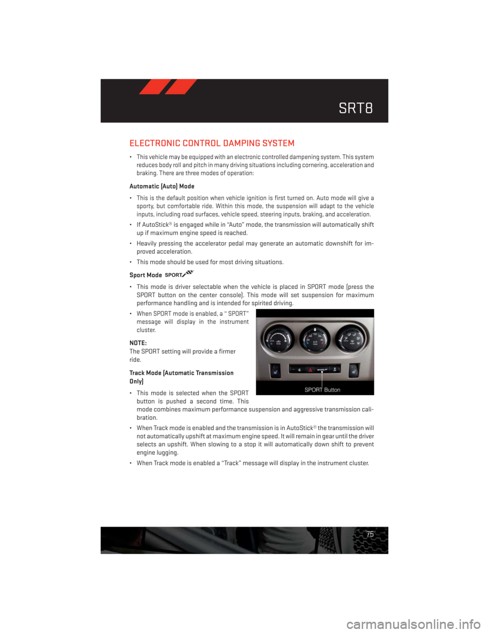
• This mode is driver selectable when the vehicle is placed in SPORT mode (press the
SPORT button on the center console). This mode will set suspension for maximum
performance handling and is intended for spirited driving.
•
When SPORT mode is enabled, a “ SPORT”
message will display in the instrument
cluster.
NOTE:
The SPORT setting will provide a firmer
ride.
Track Mode (Automatic Transmission
Only)
• This mode is selected when the SPORT
button is pushed a second time. This
mode combines maximum performance suspension and aggressive transmission cali-
bration.
• When Track mode is enabled and the transmission is in AutoStick® the transmission will
not automatically upshift at maximum engine speed. It will remain in gear until the driver
selects an upshift. When slowing to a stop it will automatically down shift to prevent
engine lugging.
• When Track mode is enabled a “Track” message will display in the instrument cluster.
SRT8
75
Page 80 of 140
ROADSIDE ASSISTANCE
•Dial toll-free 1-800-521-2779 for U.S. Residents or 1-800-363-4869 for Canadian Residents.
•Provide your name, vehicle identification number, license plate number, and your location,
including the telephone number from which you are calling.
• Briefly describe the nature of the problem and answer a few simple questions.
•
You will be given the name of the service provider and an estimated time of arrival. If you feel
you are in an “unsafe situation”, please let us know. With your consent, we will contact local
police or safety authorities.
INSTRUMENT CLUSTER WARNING LIGHTS
- Electronic Stability Control (ESC) Activation/Malfunction Indicator Light
• The “ESC Activation/Malfunction Indicator Light” in the instrument cluster will come on
when the ignition switch is turned to the ON/RUN position. It should go out with the
engine running. If the “ESC Activation/Malfunction Indicator Light” comes on continu-
ously with the engine running, a malfunction has been detected in the ESC system.
• If this light remains on after several ignition cycles, and the vehicle has been driven
several miles (kilometers) at speeds greater than 30 mph (48 km/h), we recommend you
drive to the nearest service center and have the vehicle serviced immediately.
- Tire Pressure Monitoring System (TPMS) Light
• Each tire, including the spare (if provided), should be checked monthly, when cold and
inflated to the inflation pressure recommended by the vehicle manufacturer on the
vehicle placard or tire inflation pressure label. (If your vehicle has tires of a different size
than the size indicated on the vehicle placard or tire inflation pressure label, you should
determine the proper tire inflation pressure for those tires.)
• As an added safety feature, your vehicle has been equipped with a Tire Pressure Moni-
toring System (TPMS) that illuminates a low tire pressure telltale when one or more of
your tires is significantly under-inflated. Accordingly, when the low tire pressure telltale
illuminates, you should stop and check your tires as soon as possible, and inflate them to
the proper pressure. Driving on a significantly under-inflated tire causes the tire to
overheat and can lead to tire failure. Under-inflation also reduces fuel efficiency and tire
tread life, and may affect the vehicle’s handling and stopping ability.
•IF THE LIGHT STARTS FLASHING INDICATING A LOW TIRE PRESSURE, ADJUST THE
AIR PRESSURE IN THE LOW TIRE TO THE AIR PRESSURE SHOWN ON THE VEHICLE
PLACARD OR TIRE INFLATION PRESSURE LABEL LOCATED ON THE DRIVER'S DOOR.
NOTE:
AFTER INFLATION, THE VEHICLE MAY NEED TO BE DRIVEN FOR 20 MINUTES BEFORE THE
FLASHING LIGHT WILL TURN OFF.
• Please note that the TPMS is not a substitute for proper tire maintenance, and it is the
driver’s responsibility to maintain correct tire pressure, even if under-inflation has not
reached the level to trigger illumination of the TPMS low tire pressure telltale.
WHAT TO DO IN EMERGENCIES
78
Page 112 of 140
MAINTENANCE SCHEDULE
Your vehicle is equipped with an automatic oil change indicator system. The oil change
indicator system will remind you that it is time to take your vehicle in for scheduled
maintenance.
Based on engine operation conditions, the oil change indicator message will illuminate.
This means that service is required for your vehicle. Operating conditions such as frequent
short-trips, trailer tow, extremely hot or cold ambient temperatures, and E85 fuel usage
will influence when the “Change Oil” or “Oil Change Required” message is displayed.
Severe Operating Conditions can cause the change oil message to illuminate as early as
3,500 miles (5,600 km) since last reset. Have your vehicle serviced as soon as possible,
within the next 500 miles (805 km).
On Electronic Vehicle Information Center (EVIC) equipped vehicles, “Oil Change Required”
will be displayed in the EVIC and a single chime will sound, indicating that an oil change is
necessary.
On Non-EVIC equipped vehicles, “Change Oil” will flash in the instrument cluster odometer
and a single chime will sound, indicating that an oil change is necessary.
Your authorized dealer will reset the oil change indicator message after completing the
scheduled oil change. If a scheduled oil change is performed by someone other than your
authorized dealer, the message can be reset by referring to the steps described under
“Electronic Vehicle Information Center (EVIC)/Oil Change Required” in “Understanding Your
Instrument Panel” or under “Instrument Cluster Description/Odometer/Trip Odometer” in
“Understanding Your Instrument Panel” for further information.
NOTE:
Under no circumstances should oil change intervals exceed 10,000 miles (16,000 km) or
twelve months, whichever comes first.
MAINTAINING YOUR VEHICLE
110
Page 121 of 140
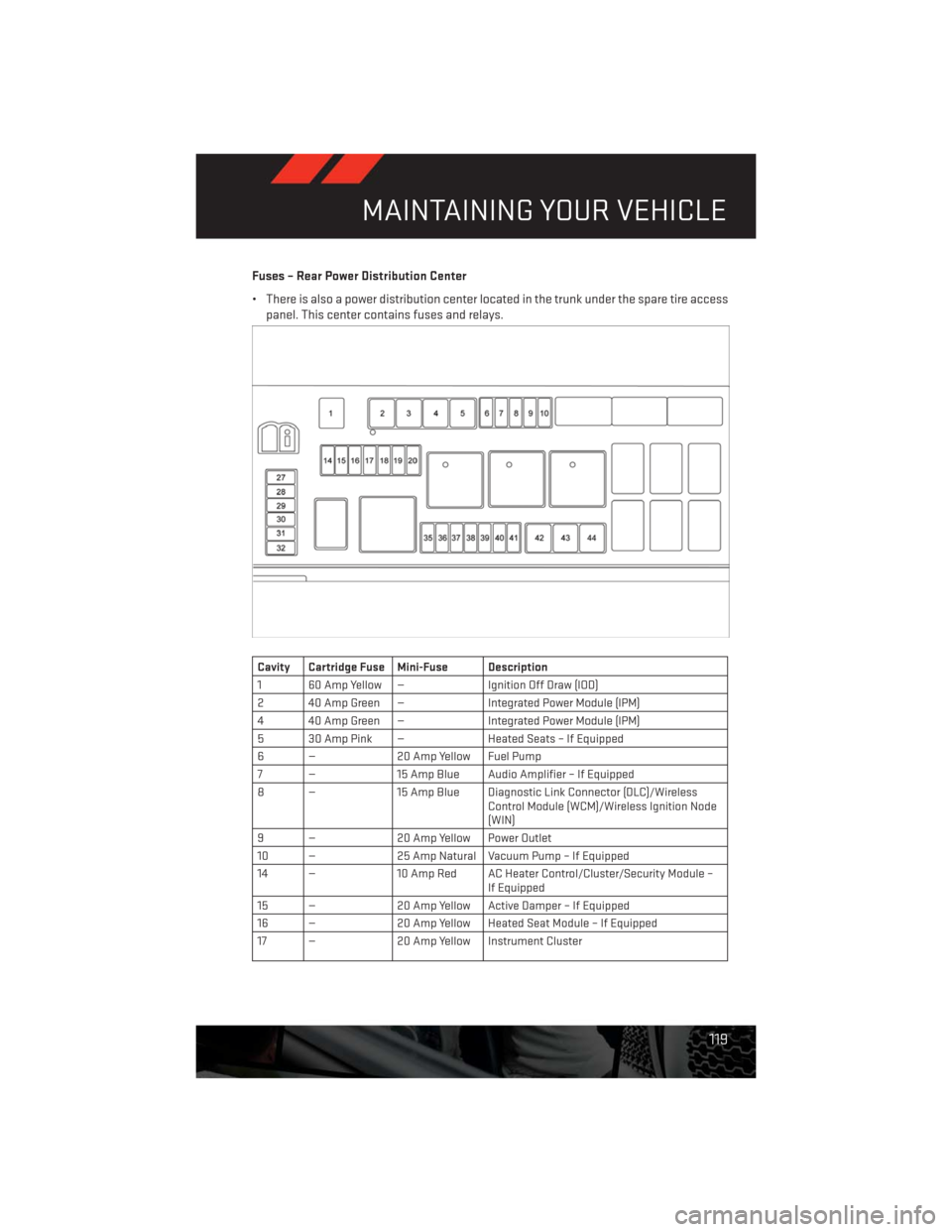
Fuses – Rear Power Distribution Center
• There is also a power distribution center located in the trunk under the spare tire access
panel. This center contains fuses and relays.
Cavity Cartridge Fuse Mini-Fuse Description
1 60 Amp Yellow — Ignition Off Draw (IOD)
2 40 Amp Green — Integrated Power Module (IPM)
4 40 Amp Green — Integrated Power Module (IPM)
5 30 Amp Pink — Heated Seats – If Equipped
6 — 20 Amp Yellow Fuel Pump
7 — 15 Amp Blue Audio Amplifier – If Equipped
8 — 15 Amp Blue Diagnostic Link Connector (DLC)/Wireless
Control Module (WCM)/Wireless Ignition Node
(WIN)
9 — 20 Amp Yellow Power Outlet
10 — 25 Amp Natural Vacuum Pump – If Equipped
14 — 10 Amp Red AC Heater Control/Cluster/Security Module –
If Equipped
15 — 20 Amp Yellow Active Damper – If Equipped
16 — 20 Amp Yellow Heated Seat Module – If Equipped
17 — 20 Amp Yellow Instrument Cluster
MAINTAINING YOUR VEHICLE
119
Page 122 of 140
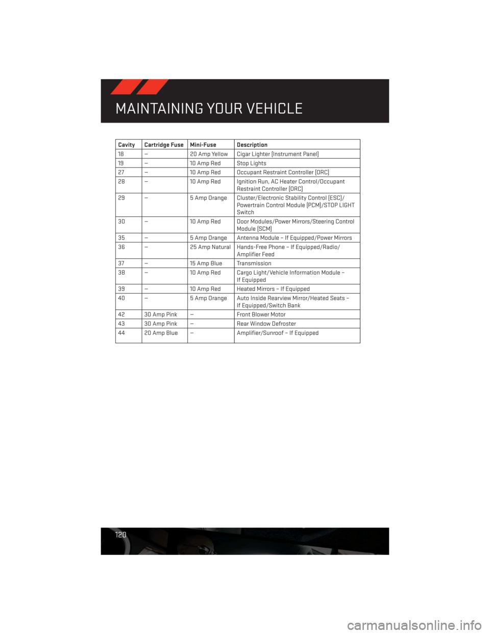
Cavity Cartridge Fuse Mini-Fuse Description
18 — 20 Amp Yellow Cigar Lighter (Instrument Panel)
19 — 10 Amp Red Stop Lights
27 — 10 Amp Red Occupant Restraint Controller (ORC)
28 — 10 Amp Red Ignition Run, AC Heater Control/Occupant
Restraint Controller (ORC)
29 — 5 Amp Orange Cluster/Electronic Stability Control (ESC)/
Powertrain Control Module (PCM)/STOP LIGHT
Switch
30 — 10 Amp Red Door Modules/Power Mirrors/Steering Control
Module (SCM)
35 — 5 Amp Orange Antenna Module – If Equipped/Power Mirrors
36 — 25 Amp Natural Hands-Free Phone – If Equipped/Radio/
Amplifier Feed
37 — 15 Amp Blue Transmission
38 — 10 Amp Red Cargo Light/Vehicle Information Module –
If Equipped
39 — 10 Amp Red Heated Mirrors – If Equipped
40 — 5 Amp Orange Auto Inside Rearview Mirror/Heated Seats –
If Equipped/Switch Bank
42 30 Amp Pink — Front Blower Motor
43 30 Amp Pink — Rear Window Defroster
44 20 Amp Blue — Amplifier/Sunroof – If Equipped
MAINTAINING YOUR VEHICLE
120
Page 128 of 140
Airbag...................14
Air Conditioning.............29
Alarm (Security Alarm)..........13
Arming Theft System (Security Alarm) . .13
Automatic Headlights..........24
Automatic Temperature Control (ATC) . .29
Automatic Transmission
Autostick.............26,74
Fluid Type..............106
Autostick...............26,74
AxleFluid ................106
Belts, Seat.................13
BrakeFluid................106
Break-In Recommendations,
New Vehicle..............22
Bulb Replacement............122
Calibration, Compass...........67
Change Oil Indicator...........81
ChangingAFlatTire...........84
Child Restraint..............15
Child Restraint Tether Anchors......15
ClimateControl..............29
Compass Calibration...........67
Cooling System
Coolant Capacity..........106
Cruise Control (Speed Control)......25
Cruise Light................25
Customer Assistance..........123
Defects, Reporting............124
DimmerControl..............24
Dimmer Switch, Headlight........24
Disarming, Theft System.........13
ECO....................67
Electronics
Your Vehicle's Sound System....32
Electronic Speed Control
(Cruise Control)............25
Electronic Vehicle Information
Center(EVIC) ...........67, 68
Emergency, In Case of
Brake Warning Light.........80
Freeing Vehicle When Stuck. . . .100
Jacking................84JumpStarting ............96
Overheating.............83
Engine
Break-In Recommendations.....22
Compartment ............103
JumpStarting ............96
Oil Selection.............106
Overheating.............83
Starting..............11, 12
Stopping..............11, 12
Event Data Recorder...........101
Exterior Lights..............122
Flat Tire Changing............84
Fluid Capacities.............106
Fluids ..................106
FogLights.................24
Folding Rear Seat.............20
Freeing A Stuck Vehicle.........100
Front Heated Seats............20
Fuel
Filler Cap (Gas Cap)..........81
Specifications
............106
Fuse ...................118
Fuses...................118
Garage Door Opener (HomeLink®)....69
Headlights
Automatic ..............24
Dimmer Switch............24
HighBeam ..............23
Heated Seats...............20
High Beam/Low Beam Select
(Dimmer) Switch............23
HomeLink® (Garage Door Opener)....69
Hood Release..............102
Instrument Cluster
Indicators...............7
Instrument Cluster Warning Lights....6
Intermittent Wipers (Delay Wipers)....23
Introduction................2
iPod®/USB/MP3 Control.........66
Bluetooth Streaming Audio.....66
INDEX
126
Page 129 of 140
Jacking Instructions...........86
Jack Location..............84
Jack Operation..............86
JumpStarting ..............96
KeyFob...................8
Key Fob Programmable Features.....68
Keyless Enter-N-Go............9
Lock/Unlock.............10
Starting/Stopping .........11, 12
Lane Change Assist...........23
Lap/Shoulder Belts............13
LATCH (Lower Anchors and Tether
for CHildren)..............15
Lights
Tire Pressure Monitoring (TPMS) . . .78
Warning (Instrument Cluster
Description)..............6
Maintenance Record.........114, 117
Maintenance Schedule.......110, 115
Malfunction Indicator Light
(CheckEngine) ............80
MOPAR® Accessories..........125
Navigation Voice Prompt Volume. . .44, 54
New Vehicle Break-In Period.......22
OilChangeIndicator ...........81
Oil Change Indicator, Reset........81
Oil, Engine
Capacity...............106
Outlet
Power .................72
Overheating, Engine...........83
Placard, Tire and Loading Information. .121
Power
Outlet (Auxiliary Electrical Outlet)...72
Seats .................18
Steering...............106
Power Sunroof..............30
Preparation for Jacking.........86
Programmable Electronic
Features..............68,76Rain Sensitive Wiper System.......23
Rear Seat, Folding............20
Recreational Towing...........73
Remote Starting System..........9
Replacement Bulbs...........122
Reporting Safety Defects........124
Rocking Vehicle When Stuck......100
Schedule, Maintenance.........110
Seat Belts.................13
Seats...................18
Adjustment..............18
Heated................20
Power .................18
Rear Folding.............20
Security Against Theft..........13
Shift Lever Override............98
Signals, Turn...............23
SpareTire.................84
Spark Plugs...............106
Speed Control
Accel/Decel.............25
Cancel................25
Resume ...............25
Set ..................25
Starting
Remote ................9
Steering
Tilt Column..............21
Steering Wheel Audio Controls......60
Stuck, Freeing..............100
Temperature Control, Automatic (ATC) . .29
Theft System Arming...........13
Theft System Disarming.........13
Tilt Steering Column...........21
TIREFIT..................90
Tires
Air Pressure.............121
Changing.............84,86
Flat Changing............84
Jacking................86
SpareTire ..............84
Towing...................73
Disabled Vehicle...........99
Recreational.............73
INDEX
127