warning DODGE CHALLENGER 2015 3.G Owners Manual
[x] Cancel search | Manufacturer: DODGE, Model Year: 2015, Model line: CHALLENGER, Model: DODGE CHALLENGER 2015 3.GPages: 603, PDF Size: 14.97 MB
Page 211 of 603
WARNING!(Continued)
•Do not allow small children to operate the sunroof.
Never allow your fingers, other body parts, or any
object, to project through the sunroof opening.
Injury may result.
Opening Sunroof — Express
Press the switch rearward and release it within one-half
second. The sunroof and sunshade will open automati-
cally from any position. The sunroof and sunshade will
open fully and stop automatically. This is called “Express
Open”. During Express Open operation, any movement
of the sunroof switch will stop the sunroof.
Opening Sunroof — Manual Mode
To open the sunroof, press and hold the switch rearward
to full open. Any release of the switch will stop the
movement. The sunroof and sunshade will remain in a
partially opened condition until the switch is pushed and
held rearward again.
Closing Sunroof — Express
Press the switch forward and release it within one-half
second and the sunroof will close automatically from any
position. The sunroof will close fully and stop automati-
cally. This is called “Express Close”. During Express
Close operation, any movement of the switch will stop
the sunroof.
Closing Sunroof — Manual Mode
To close the sunroof, press and hold the switch in the
forward position. Any release of the switch will stop the
movement and the sunroof will remain in a partially
closed condition until the switch is pushed and held
forward again.
3
UNDERSTANDING THE FEATURES OF YOUR VEHICLE 209
Page 216 of 603
WARNING!
To avoid serious injury or death:
•Only devices designed for use in this type of outlet
should be inserted into any 12 Volt outlet.
•Do not touch with wet hands.
•Close the lid when not in use and while driving the
vehicle.
•If this outlet is mishandled, it may cause an electric
shock and failure.
CAUTION!
•Many accessories that can be plugged in draw
power from the vehicle’s battery, even when not in
use (i.e., cellular phones, etc.). Eventually, if
plugged in long enough, the vehicle’s battery will
discharge sufficiently to degrade battery life and/or
prevent the engine from starting.
•Accessories that draw higher power (i.e., coolers,
vacuum cleaners, lights, etc.), will degrade the
battery even more quickly. Only use these intermit-
tently and with greater caution.
•After the use of high power draw accessories, or
long periods of the vehicle not being started (with
accessories still plugged in), the vehicle must be
driven a sufficient length of time to allow the
alternator to recharge the vehicle’s battery.
(Continued)
214 UNDERSTANDING THE FEATURES OF YOUR VEHICLE
Page 220 of 603
WARNING!
Do not operate this vehicle with a console compart-
ment lid in the open position. Driving with the
console compartment lid open may result in injury in
a collision.
REAR WINDOW FEATURES
Rear Window Defroster
The rear window defroster button is located on
the climate control (Mode) knob. Press this button
to turn on the rear window defroster and the heated
outside mirrors (if equipped). An indicator in the button
will illuminate when the rear window defroster is on. The
rear window defroster automatically turns off after ap-
proximately 10 minutes. For an additional five minutes of
operation, press the button a second time.
NOTE:To prevent excessive battery drain, use the rear
window defroster only when the engine is operating.
CAUTION!
Failure to follow these cautions can cause damage to
the heating elements:
•Use care when washing the inside of the rear
window. Do not use abrasive window cleaners on
the interior surface of the window. Use a soft cloth
and a mild washing solution, wiping parallel to the
heating elements. Labels can be peeled off after
soaking with warm water.
•Do not use scrapers, sharp instruments, or abrasive
window cleaners on the interior surface of the
window.
•Keep all objects a safe distance from the window.
218 UNDERSTANDING THE FEATURES OF YOUR VEHICLE
Page 226 of 603
INSTRUMENT CLUSTER DESCRIPTIONS
1. Tachometer
The red segments indicate the maximum permissible
engine revolutions per minute (RPM x 1000) for each gear
range. Ease up on the accelerator before reaching the red
area.
2. Malfunction Indicator Light (MIL)
The Malfunction Indicator Light (MIL) is part of
an onboard diagnostic system called OBD. The
OBD system monitors engine and automatic
transmission control systems. The MIL will turn on when
the ignition is in the ON/RUN position before engine
start. If the MIL does not come on when turning the key
from OFF to ON/RUN, have the condition checked
promptly.
Certain conditions, such as a loose or missing gas cap,
poor fuel quality, etc., may illuminate the MIL after
engine start. The vehicle should be serviced if the MIL
stays on through several of your typical driving cycles. In
most situations, the vehicle will drive normally and will
not require towing.
CAUTION!
Prolonged driving with the Malfunction Indicator
Light (MIL) on could cause damage to the engine
control system. It also could affect fuel economy and
driveability. If the MIL is flashing, severe catalytic
converter damage and power loss will soon occur.
Immediate service is required.
WARNING!
A malfunctioning catalytic converter, as referenced
above, can reach higher temperatures than in normal
(Continued)
224 UNDERSTANDING YOUR INSTRUMENT PANEL
Page 227 of 603
WARNING!(Continued)
operating conditions. This can cause a fire if you
drive slowly or park over flammable substances such
as dry plants, wood, cardboard, etc. This could result
in death or serious injury to the driver, occupants or
others.
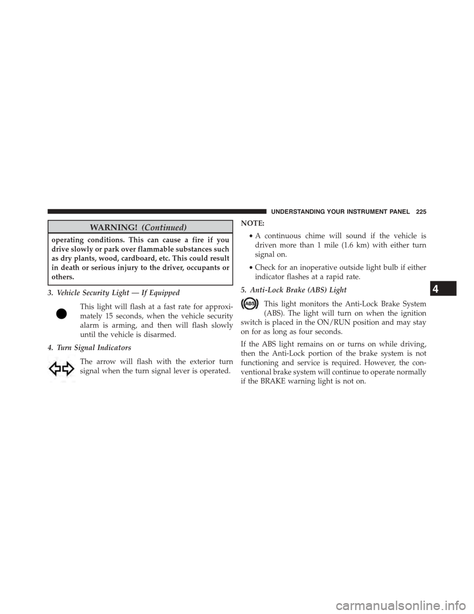
3. Vehicle Security Light — If Equipped
This light will flash at a fast rate for approxi-
mately 15 seconds, when the vehicle security
alarm is arming, and then will flash slowly
until the vehicle is disarmed.
4. Turn Signal Indicators
The arrow will flash with the exterior turn
signal when the turn signal lever is operated.
NOTE:
•A continuous chime will sound if the vehicle is
driven more than 1 mile (1.6 km) with either turn
signal on.
•Check for an inoperative outside light bulb if either
indicator flashes at a rapid rate.
5. Anti-Lock Brake (ABS) Light
This light monitors the Anti-Lock Brake System
(ABS). The light will turn on when the ignition
switch is placed in the ON/RUN position and may stay
on for as long as four seconds.
If the ABS light remains on or turns on while driving,
then the Anti-Lock portion of the brake system is not
functioning and service is required. However, the con-
ventional brake system will continue to operate normally
if the BRAKE warning light is not on.
4
UNDERSTANDING YOUR INSTRUMENT PANEL 225
Page 229 of 603
7. Gear Status Indicator — Automatic Transmission
Only
The Gear Status Indicator is self-contained within the
instrument cluster. It displays the gear position of the
automatic transmission.
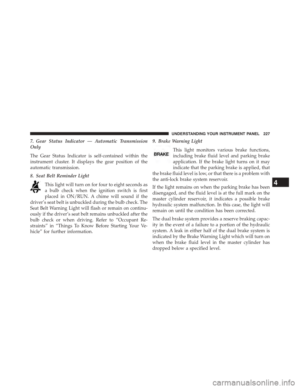
8. Seat Belt Reminder Light
This light will turn on for four to eight seconds as
a bulb check when the ignition switch is first
placed in ON/RUN. A chime will sound if the
driver’s seat belt is unbuckled during the bulb check. The
Seat Belt Warning Light will flash or remain on continu-
ously if the driver’s seat belt remains unbuckled after the
bulb check or when driving. Refer to “Occupant Re-
straints” in “Things To Know Before Starting Your Ve-
hicle” for further information.
9. Brake Warning Light
This light monitors various brake functions,
including brake fluid level and parking brake
application. If the brake light turns on it may
indicate that the parking brake is applied, that
the brake fluid level is low, or that there is a problem with
the anti-lock brake system reservoir.
If the light remains on when the parking brake has been
disengaged, and the fluid level is at the full mark on the
master cylinder reservoir, it indicates a possible brake
hydraulic system malfunction. In this case, the light will
remain on until the condition has been corrected.
The dual brake system provides a reserve braking capac-
ity in the event of a failure to a portion of the hydraulic
system. A leak in either half of the dual brake system is
indicated by the Brake Warning Light which will turn on
when the brake fluid level in the master cylinder has
dropped below a specified level.
4
UNDERSTANDING YOUR INSTRUMENT PANEL 227
Page 230 of 603
The light will remain on until the cause is corrected.
NOTE:The light may flash momentarily during sharp
cornering maneuvers which change fluid level condi-
tions. The vehicle should have service performed, and
the brake fluid level checked.
If brake failure is indicated, immediate repair is neces-
sary.
WARNING!
Driving a vehicle with the brake light on is danger-
ous. Part of the brake system may have failed. It will
take longer to stop the vehicle. You could have a
collision. Have the vehicle checked immediately.
Vehicles equipped with the Anti-Lock Brake System
(ABS), are also equipped with Electronic Brake Force
Distribution (EBD). In the event of an EBD failure, the
Brake Warning Light will turn on along with the ABS
Light. Immediate repair to the ABS system is required.
Operation of the Brake Warning Light can be checked by
turning the ignition switch from the OFF position to the
ON/RUN position. The light should illuminate for ap-
proximately two seconds. The light should then turn off
unless the parking brake is applied or a brake fault is
detected. If the light does not illuminate, have the light
inspected by an authorized dealer.
The light also will turn on when the parking brake is
applied with the ignition switch in the ON/RUN posi-
tion.
NOTE:This light shows only that the parking brake is
applied. It does not show the degree of brake application.
228 UNDERSTANDING YOUR INSTRUMENT PANEL
Page 231 of 603
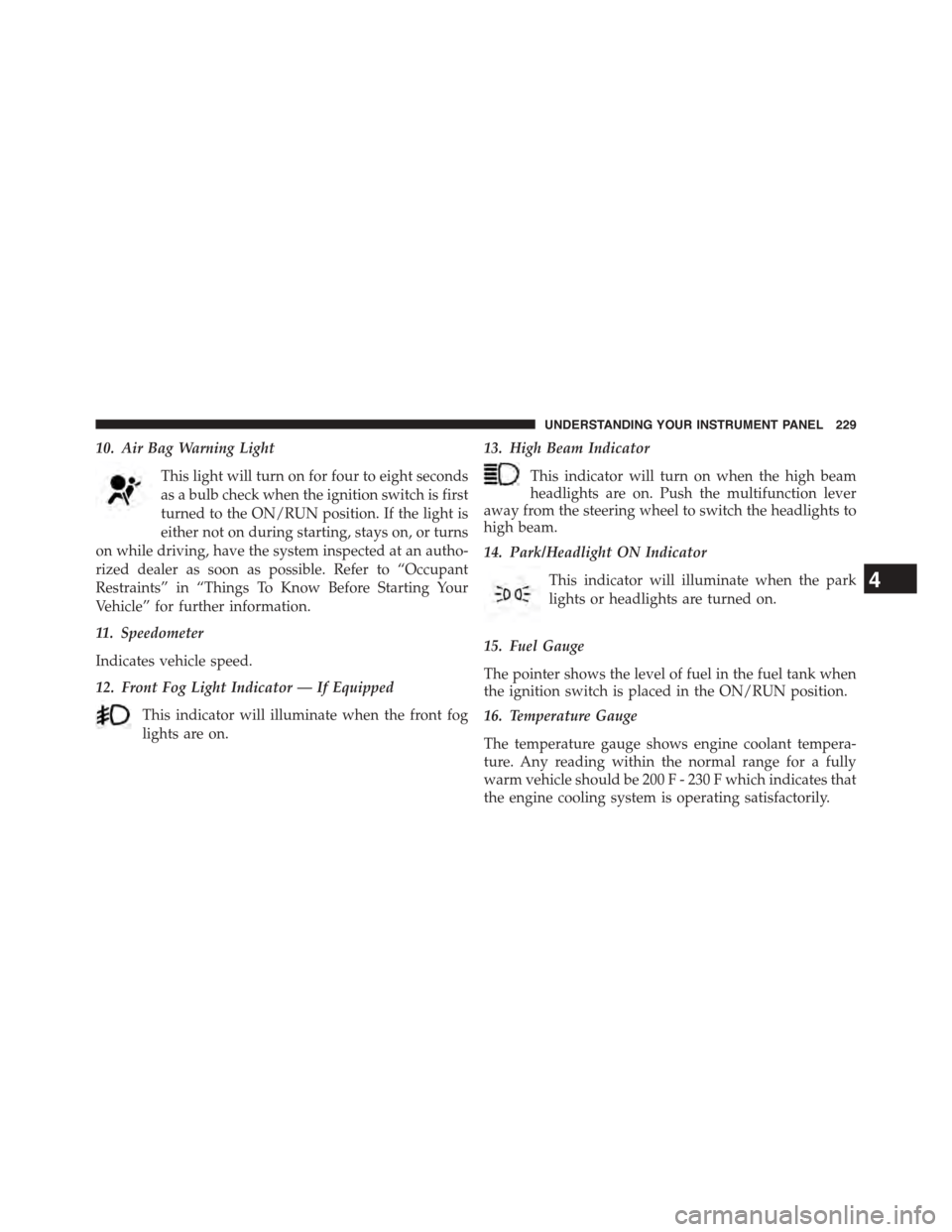
10. Air Bag Warning Light
This light will turn on for four to eight seconds
as a bulb check when the ignition switch is first
turned to the ON/RUN position. If the light is
either not on during starting, stays on, or turns
on while driving, have the system inspected at an autho-
rized dealer as soon as possible. Refer to “Occupant
Restraints” in “Things To Know Before Starting Your
Vehicle” for further information.
11. Speedometer
Indicates vehicle speed.
12. Front Fog Light Indicator — If Equipped
This indicator will illuminate when the front fog
lights are on.
13. High Beam Indicator
This indicator will turn on when the high beam
headlights are on. Push the multifunction lever
away from the steering wheel to switch the headlights to
high beam.
14. Park/Headlight ON Indicator
This indicator will illuminate when the park
lights or headlights are turned on.
15. Fuel Gauge
The pointer shows the level of fuel in the fuel tank when
the ignition switch is placed in the ON/RUN position.
16. Temperature Gauge
The temperature gauge shows engine coolant tempera-
ture. Any reading within the normal range for a fully
warm vehicle should be 200 F - 230 F which indicates that
the engine cooling system is operating satisfactorily.
4
UNDERSTANDING YOUR INSTRUMENT PANEL 229
Page 232 of 603
The gauge pointer will likely indicate a higher tempera-
ture when driving in hot weather, up mountain grades,
or when towing a trailer. It should not be allowed to
exceed the upper limits of the normal operating range.
CAUTION!
Driving with a hot engine cooling system could
damage your vehicle. If the temperature gauge reads
“H,” pull over and stop the vehicle. Idle the vehicle
with the air conditioner turned off until the pointer
drops back into the normal range. If the pointer
remains on the “H,” and you hear a chime, turn the
engine OFF immediately and call for service.
WARNING!
A hot engine cooling system is dangerous. You or
others could be badly burned by steam or boiling
(Continued)
WARNING!(Continued)
coolant. You may want to call a service center if your
vehicle overheats. If you decide to look under the
hood yourself, refer to “Maintaining Your Vehicle”
and follow the warnings under the Cooling System
Pressure Cap paragraph.
17. Tire Pressure Monitoring Telltale Light
Each tire, including the spare (if provided),
should be checked monthly when cold and
inflated to the inflation pressure recommended
by the vehicle manufacturer on the vehicle
placard or tire inflation pressure label. (If your vehicle
has tires of a different size than the size indicated on the
vehicle placard or tire inflation pressure label, you should
determine the proper tire inflation pressure for those
tires.)
230 UNDERSTANDING YOUR INSTRUMENT PANEL
Page 234 of 603
CAUTION!
The TPMS has been optimized for the original
equipment tires and wheels. TPMS pressures and
warning have been established for the tire size
equipped on your vehicle. Undesirable system opera-
tion or sensor damage may result when using re-
placement equipment that is not of the same size,
type, and/or style. Aftermarket wheels can cause
sensor damage. Do not use tire sealant from a can or
balance beads if your vehicle is equipped with a
TPMS, as damage to the sensors may result.
18. Electronic Stability Control (ESC) OFF Indicator
Light — If Equipped
This light indicates the Electronic Stability Con-
trol (ESC) is off.
With Drive Modes the ESC OFF indicator will
be lit any time the Traction modes is set to Sport, Track or
Full OFF.
232 UNDERSTANDING YOUR INSTRUMENT PANEL