DODGE CHALLENGER 2015 3.G Owners Manual
Manufacturer: DODGE, Model Year: 2015, Model line: CHALLENGER, Model: DODGE CHALLENGER 2015 3.GPages: 603, PDF Size: 14.97 MB
Page 381 of 603
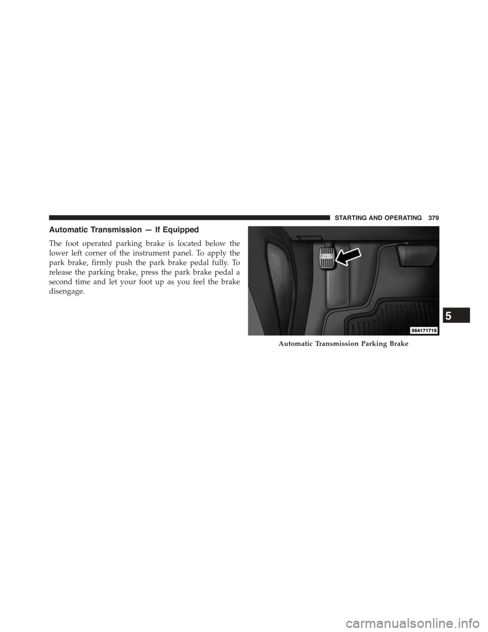
Automatic Transmission — If Equipped
The foot operated parking brake is located below the
lower left corner of the instrument panel. To apply the
park brake, firmly push the park brake pedal fully. To
release the parking brake, press the park brake pedal a
second time and let your foot up as you feel the brake
disengage.
Automatic Transmission Parking Brake
5
STARTING AND OPERATING 379
Page 382 of 603
WARNING!
•Never use the PARK position as a substitute for the
parking brake. Always apply the parking brake
fully when parked to guard against vehicle move-
ment and possible injury or damage.
•When leaving the vehicle, always remove the Key
Fob from the ignition and lock your vehicle.
•Never leave children alone in a vehicle, or with
access to an unlocked vehicle. Allowing children to
be in a vehicle unattended is dangerous for a
number of reasons. A child or others could be
seriously or fatally injured. Children should be
warned not to touch the parking brake, brake pedal
or the shift lever.
(Continued)
WARNING!(Continued)
•Do not leave the Key Fob in or near the vehicle (or
in a location accessible to children), and do not
leave the ignition of a vehicle equipped with
Keyless Enter-N-Go™ in the ACC or ON/RUN
mode. A child could operate power windows, other
controls, or move the vehicle.
•Be sure the parking brake is fully disengaged
before driving; failure to do so can lead to brake
failure and a collision.
•Always fully apply the parking brake when leav-
ing your vehicle, or it may roll and cause damage or
injury. Also be certain to leave the transmission in
PARK. Failure to do so may allow the vehicle to roll
and cause damage or injury.
380 STARTING AND OPERATING
Page 383 of 603
CAUTION!
If the “Brake Warning Light” remains on with the
parking brake released, a brake system malfunction
is indicated. Have the brake system serviced by an
authorized dealer immediately.
BRAKE SYSTEM
Your vehicle is equipped with dual hydraulic
brake systems. If either of the two hydraulic
systems loses normal capability, the remaining
system will still function. There will be some
loss of overall braking effectiveness. This may be evident
by increased pedal travel during application, greater
pedal force required to slow or stop, and potential
activation of the “Brake Warning Light.”
In the event power assist is lost for any reason (for
example, repeated brake applications with the engine
OFF) the brakes will still function. The effort required to
brake the vehicle will be much greater than that required
with the power system operating.
NOTE:Your vehicle is equipped with a high perfor-
mance braking system. The brake pads are a semi-
metallic compound, which offer superior fade resistance
for consistent operation. A compromise to using this type
of brake pad is that the brakes may produce more brake
dust and may squeal slightly under certain weather and
operating conditions (.i.e., during light brake applica-
tions) this is considered normal conditions.
ELECTRONIC BRAKE CONTROL SYSTEM
Your vehicle is equipped with an advanced electronic
brake control system commonly referred to as ESC. This
system includes the ABS (Anti-Lock Brake System), the
TCS (Traction Control System), the BAS (Brake Assist
5
STARTING AND OPERATING 381
Page 384 of 603
System), and the ESC (Electronic Stability Control). These
systems work together to enhance both vehicle stability
and control in various driving conditions.
An additional electronic brake control feature called Hill
Start Assist (HSA) is standard on all models.
Anti-Lock Brake System (ABS)
The Anti-Lock Brake System (ABS) provides increased
vehicle stability and brake performance under most
braking conditions. The system automatically “pumps”
the brakes during severe braking conditions to prevent
wheel lock-up.
The Electronic Brake Force Distribution (EBD) prevents the
rear wheels from over-braking and provides greater control
of available braking forces applied to the rear axle.
When the vehicle is driven over 7 mph (11 km/h), you
may also hear a slight clicking sound as well as some
related motor noises. These noises are the system per-
forming its self check cycle to ensure that the ABS system
is working properly. This self check occurs each time the
vehicle is started and accelerated past 7 mph (11 km/h).
ABS is activated during braking under certain road or
stopping conditions. ABS-inducing conditions can in-
clude ice, snow, gravel, bumps, railroad tracks, loose
debris, or panic stops.
You also may experience the following when the brake
system goes into anti-lock:
•The ABS motor running (it may continue to run for a
short time after the stop)
•The clicking sound of solenoid valves
•Brake pedal pulsations
•A slight drop or fall away of the brake pedal at the end
of the stop
These are all normal characteristics of ABS.
382 STARTING AND OPERATING
Page 385 of 603
WARNING!
•The Anti-Lock Brake System (ABS) contains so-
phisticated electronic equipment that may be sus-
ceptible to interference caused by improperly in-
stalled or high output radio transmitting
equipment. This interference can cause possible
loss of anti-lock braking capability. Installation of
such equipment should be performed by qualified
professionals.
•Pumping of the Anti-Lock Brakes will diminish
their effectiveness and may lead to a collision.
Pumping makes the stopping distance longer. Just
press firmly on your brake pedal when you need to
slow down or stop.
(Continued)
WARNING!(Continued)
•The Anti-Lock Brake System (ABS) cannot prevent
the natural laws of physics from acting on the
vehicle, nor can it increase braking or steering
efficiency beyond that afforded by the condition of
the vehicle brakes and tires or the traction afforded.
•The Anti-Lock Brake System (ABS) cannot prevent
collisions, including those resulting from excessive
speed in turns, following another vehicle too
closely, or hydroplaning.
•The capabilities of an Anti-Lock Brake System
(ABS) equipped vehicle must never be exploited in
a reckless or dangerous manner, that could jeopar-
dize the user’s safety or the safety of others.
All vehicle wheels and tires must be the same size and
type and tires must be properly inflated to produce
accurate signals for the computer.
5
STARTING AND OPERATING 383
Page 386 of 603
Anti-Lock Brake Warning Light
The “Anti-Lock Brake System (ABS) Warning
Light” monitors the Anti-Lock Brake System. The
light will come on when the ignition switch is
turned to the ON position and may stay on for as long as
four seconds.
If the “ABS Warning Light” remains on or comes on
while driving, it indicates that the anti-lock portion of the
brake system is not functioning and that service is
required. However, the conventional brake system will
continue to operate normally if the “Brake Warning
Light” is not on.
If the “ABS Warning Light” is on, the brake system
should be serviced as soon as possible to restore the
benefits of anti-lock brakes. If the “ABS Warning Light”
does not come on when the ignition switch is turned to
the ON position, have the bulb repaired as soon as
possible.
If both the “Brake Warning Light” and the “ABS Warning
Light” remain on, the ABS and EBD systems are not
functioning. Immediate repair to the ABS system is
required.
Traction Control System (TCS)
This system monitors the amount of wheel spin of each
driven wheel. If wheel spin is detected, brake pressure is
applied to the slipping wheel(s) and engine power is
reduced to provide enhanced acceleration and stability.
A feature of the TCS system, Brake Limited Differential
(BLD), controls the wheel spin across a driven axle. If one
wheel on a driven axle is spinning faster than the other,
the system will apply the brake of the spinning wheel.
This will allow more engine torque to be applied to the
wheel that is not spinning. This feature remains active
even if TCS and ESC are in the “Partial Off” or#Full Off#
mode. Refer to “Electronic Stability Control (ESC)” in this
section for more information.
384 STARTING AND OPERATING
Page 387 of 603
Brake Assist System (BAS)
This system complements the ABS by optimizing the
vehicle braking capability during emergency braking
maneuvers. This system detects an emergency braking
situation by sensing the rate and amount of brake appli-
cation and then applies optimum pressure to the brakes.
This can help reduce braking distances.
Applying the brakes very quickly results in the best BAS
assistance. To receive the benefits of this system, you
must apply continuous brake pedal pressure during the
stopping sequence. Do not reduce brake pedal pressure
unless braking is no longer desired. Once the brake pedal
is released, the BAS is deactivated.
WARNING!
The BAS cannot prevent the natural laws of physics
from acting on the vehicle, nor can it increase the
(Continued)
WARNING!(Continued)
traction afforded by prevailing road conditions. The
BAS cannot prevent collisions, including those re-
sulting from excessive speed in turns, driving on
very slippery surfaces, or hydroplaning. The capa-
bilities of a BAS-equipped vehicle must never be
exploited in a reckless or dangerous manner that
could jeopardize the user’s safety or the safety of
others.
Hill Start Assist (HSA)
The HSA system is designed to assist the driver when
starting a vehicle from a stop on a hill. HSA will maintain
the level of brake pressure the driver applied for a short
period of time after the driver takes their foot off of the
brake pedal. If the driver does not apply the throttle
during this short period of time, the system will release
brake pressure and the vehicle will roll down the hill. The
5
STARTING AND OPERATING 385
Page 388 of 603
system will release brake pressure in proportion to
amount of throttle applied as the vehicle starts to move in
the intended direction of travel.
HSA Activation Criteria
The following criteria must be met in order for HSA to
activate:
•Vehicle must be stopped.
•Vehicle must be on a 3% (approximate) for manual
transmission and 6% (approximate) for automatic
transmissions.
•Gear selection matches vehicle uphill direction (i.e.,
vehicle facing uphill is in forward gear; vehicle back-
ing uphill is in REVERSE gear).
WARNING!
There may be situations on minor hills with a loaded
vehicle, or while pulling a trailer, when the system
will not activate and slight rolling may occur. This
could cause a collision with another vehicle or object.
Always remember the driver is responsible for brak-
ing the vehicle.
HSA Off
If you wish to turn off the HSA system, it can be done in
the Uconnect® settings. Refer to#Uconnect® Settings#in
#Understanding Your Instrument Panel#for further infor-
mation.
Electronic Stability Control (ESC)
This system enhances directional control and stability of
the vehicle under various driving conditions. The ESC
corrects for oversteering and understeering the vehicle
386 STARTING AND OPERATING
Page 389 of 603
by applying the brake of the appropriate wheel. Engine
power may also be reduced to assist in counteracting the
condition of oversteer or understeer and help the vehicle
maintain the desired path.
The ESC uses sensors in the vehicle to determine the path
that the driver intends to steer the vehicle and compares
it to the actual path of the vehicle. When the actual path
does not match the intended path, the ESC applies the
brake of the appropriate wheel to assist in counteracting
the condition of oversteer or understeer.
•Oversteer - when the vehicle is turning more than
appropriate for the steering wheel position.
•Understeer - when the vehicle is turning less than
appropriate for the steering wheel position.
WARNING!
The Electronic Stability Control System (ESC) cannot
prevent the natural laws of physics from acting on
the vehicle, nor can it increase the traction afforded
by prevailing road conditions. ESC cannot prevent
all accidents, including those resulting from exces-
sive speed in turns, driving on very slippery surfaces,
or hydroplaning. ESC also cannot prevent accidents
resulting from loss of vehicle control due to inappro-
priate driver input for the conditions. Only a safe,
attentive, and skillful driver can prevent accidents.
The capabilities of an ESC equipped vehicle must
never be exploited in a reckless or dangerous manner
which could jeopardize the user ’s safety or the safety
of others.
5
STARTING AND OPERATING 387
Page 390 of 603
ESC Operating Modes
The ESC system has two or three available operating
modes:
ESC On
This is the normal operating mode for the ESC. When-
ever the vehicle is started, the ESC system will be in this
mode. This mode should be used for most driving
situations. The ESC should only be turned OFF for
specific reasons as noted in the following paragraphs.
Partial Off
The “Partial Off” mode is intended for times when a
more spirited driving experience is desired. It is also
intended for driving in deep snow, sand, or gravel. This
mode disables the TCS portion of the ESC and raises the
threshold for ESC activation, which allows for more
wheel spin than what ESC normally allows. The “ESC
Off” switch is located in the switch bank near the bottom
center of the instrument panel or in the touchscreen radio
. To enter the “Partial Off” mode, momentarily press the
“ESC Off” switch and the “ESC Off Indicator Light” will
illuminate. To turn the ESC ON again, momentarily press
the “ESC Off” switch and the “ESC Off Indicator Light”
will turn off.
NOTE:To improve the vehicle’s traction when driving
with snow chains, or when starting off in deep snow,
sand, or gravel, it may be desirable to switch to the
“Partial Off” mode by momentarily pressing the “ESC
Off” switch. Once the situation requiring “Partial Off”
mode is overcome, turn the ESC ON again by momen-
tarily pressing the “ESC Off” switch. This may be done
while the vehicle is in motion.
388 STARTING AND OPERATING