parking brake DODGE CHALLENGER 2015 3.G Owners Manual
[x] Cancel search | Manufacturer: DODGE, Model Year: 2015, Model line: CHALLENGER, Model: DODGE CHALLENGER 2015 3.GPages: 603, PDF Size: 14.97 MB
Page 17 of 603
WARNING!(Continued)
•Allowing children to be in a vehicle unattended is
dangerous for a number of reasons. A child or
others could be seriously or fatally injured. Chil-
dren should be warned not to touch the parking
brake, brake pedal or the transmission gear selec-
tor.
•Do not leave the Key Fob in or near the vehicle, or
in a location accessible to children, and do not
leave the ignition of a vehicle equipped with
Keyless Enter-N-Go™ in the ACC or ON/RUN
mode. A child could operate power windows, other
controls, or move the vehicle.
•Do not leave children or animals inside parked
vehicles in hot weather. Interior heat build-up may
cause serious injury or death.
CAUTION!
An unlocked car is an invitation to thieves. Always
remove the Key Fob from vehicle, cycle the ignition
OFF and lock all doors when leaving the vehicle
unattended.
SENTRY KEY®
The Sentry Key® Immobilizer system prevents unauthor-
ized vehicle operation by disabling the engine. The
system does not need to be armed or activated. Operation
is automatic, regardless of whether the vehicle is locked
or unlocked.
The system uses a Key Fob with a factory-mated Remote
Keyless Entry (RKE) transmitter, a Keyless Ignition Node
(KIN) and a RF receiver to prevent unauthorized vehicle
operation. Therefore, only Key Fobs that are pro-
grammed to the vehicle can be used to start and operate
2
THINGS TO KNOW BEFORE STARTING YOUR VEHICLE 15
Page 32 of 603
If the door lock knob is down when you shut the door,
the door will lock. Therefore, make sure the Key Fob is
not inside the vehicle before closing the door.
WARNING!
•For personal security and safety in the event of a
collision, lock the vehicle doors before you drive as
well as when you park and leave the vehicle.
•When leaving the vehicle, always remove the Key
Fob from the ignition and lock your vehicle.
•Never leave children alone in a vehicle, or with
access to an unlocked vehicle. Allowing children to
be in a vehicle unattended is dangerous for a
number of reasons. A child or others could be
seriously or fatally injured. Children should be
warned not to touch the parking brake, brake pedal
or the transmission gear selector.
(Continued)
WARNING!(Continued)
•Do not leave the Key Fob in or near the vehicle, or
in a location accessible to children, and do not
leave the ignition of a vehicle equipped with
Keyless Enter-N-Go™ in the ACC or ON/RUN
mode. A child could operate power windows, other
controls, or move the vehicle.
30 THINGS TO KNOW BEFORE STARTING YOUR VEHICLE
Page 99 of 603
Periodic Safety Checks You Should Make Outside
The Vehicle
Tires
Examine tires for excessive tread wear and uneven wear
patterns. Check for stones, nails, glass, or other objects
lodged in the tread or sidewall. Inspect the tread for cuts
and cracks. Inspect sidewalls for cuts, cracks and bulges.
Check the wheel nuts for tightness. Check the tires
(including spare) for proper cold inflation pressure.
Lights
Have someone observe the operation of brake lights and
exterior lights while you work the controls. Check turn
signal and high beam indicator lights on the instrument
panel.
Door Latches
Check for positive closing, latching, and locking.
Fluid Leaks
Check area under vehicle after overnight parking for fuel,
engine coolant, oil, or other fluid leaks. Also, if gasoline
fumes are detected or if fuel, power steering fluid (if
equipped), or brake fluid leaks are suspected, the cause
should be located and corrected immediately.
2
THINGS TO KNOW BEFORE STARTING YOUR VEHICLE 97
Page 143 of 603
2. Push back on the multifunction lever once again to
reactivate the system.
Headlight Time Delay
This feature provides the safety of headlight illumination
for up to 90 seconds when leaving your vehicle in an
unlit area.
To activate the delay feature, turn OFF the ignition switch
while the headlights are still on. Then, turn off the
headlights within 45 seconds. The delay interval begins
when the headlight switch is turned off.
NOTE:The lights must be turned off within 45 seconds
of turning the ignition OFF to activate this feature.
If you turn the headlights, park lights or ignition switch
ON again, the system will cancel the delay.
If you turn the headlights off before the ignition, they will
turn off in the normal manner.
NOTE:The Headlight Time Delay is programmable us-
ing the Uconnect® System, refer to “Uconnect® Settings”
in “Understanding Your Instrument Panel” for further
information.
Daytime Running Lights (DRL) — If Equipped
The Daytime Running Lights will turn On when the
engine is started and remain On unless the headlamps
are turned ON, the parking brake is applied, or the
engine is shut Off.
NOTE:If allowed by law in the country in which the
vehicle was purchased the Daytime Running Lights can
be turned on and off using the Uconnect® System, refer
to “Uconnect® Settings” in “Understanding Your Instru-
ment Panel” for further information.
3
UNDERSTANDING THE FEATURES OF YOUR VEHICLE 141
Page 164 of 603
NOTE:Any chassis/suspension or tire size modifications
to the vehicle will effect the performance of the Adaptive
Cruise Control and Forward Collision Warning System.
Activating Adaptive Cruise Control (ACC)
You can only engage ACC if the vehicle speed is above
20 mph (32 km/h).
The system will cancel when the vehicle speed drops
below 15 mph (24 km/h).
The minimum Set Speed for the ACC system is 20 mph
(32 km/h).
When the system is turned on and in the READY state,
the Driver Information Display (DID) displays “ACC
Ready.”
When the system is OFF, the DID displays “Adaptive
Cruise Control (ACC) Off.”
NOTE:You cannot engage ACC under the following
conditions:
•When you apply the brakes.
•When the parking brake is set.
•When the automatic transmission is in PARK, RE-
VERSE or NEUTRAL.
•When the Vehicle speed is outside of the speed range.
•When the brakes are overheated.
To Activate/Deactivate
Push and release the Adaptive Cruise Control (ACC)
ON/OFF button. The ACC menu in the DID displays
“ACC Ready.”
162 UNDERSTANDING THE FEATURES OF YOUR VEHICLE
Page 166 of 603
WARNING!(Continued)
want. You could lose control and have a collision.
Always leave the system off when you are not using
it.
To Set A Desired ACC Speed
When the vehicle reaches the speed desired, push the
SET+button or the SET-button and release. The DID
will display the set speed.
If the system is Set when the vehicle speed is above
20 mph (32 km/h), the Set Speed shall be the current
speed of the vehicle.
Remove your foot from the accelerator pedal. If you do
not, the vehicle may continue to accelerate beyond the set
speed. If this occurs:
•The message “DRIVER OVERRIDE” will display in
the DID.
•The system will not be controlling the distance be-
tween your vehicle and the vehicle ahead. The vehicle
speed will only be determined by the position of the
accelerator pedal.
To Cancel
The following conditions cancel the system:
•The brake pedal is applied.
•The CANCEL button is pressed.
•The vehicle speed goes below 15 mph (25 km/h).
•An Anti-Lock Brake System (ABS) event occurs.
•The shift lever/gear selector is removed from the
Drive position.
•The Electronic Stability Control/Traction Control Sys-
tem (ESC/TCS) activates.
•The vehicle parking brake is applied.
164 UNDERSTANDING THE FEATURES OF YOUR VEHICLE
Page 184 of 603
To Cancel
The following conditions will cancel the Normal (Fixed
Speed) Electronic Speed Control without clearing the
memory:
•The brake pedal is applied.
•The CANCEL button is pressed.
•The Electronic Stability Control/Traction Control Sys-
tem (ESC/TCS) activates.
•The vehicle parking brake is applied.
•The braking temperature exceeds normal range (over-
heated).
•The shift lever/gear selector is removed from the
Drive position.
To Resume Speed
To resume a previously set speed, push the RES button
and release. Resume can be used at any speed above
20 mph (32 km/h).
To Turn Off
The system will turn off and erase the set speed in
memory if:
•The Normal (Fixed Speed) Electronic Speed Control
ON/OFF button is pressed.
•The ignition is turned off.
•The Adaptive Cruise Control (ACC) On/Off button is
pressed.
182 UNDERSTANDING THE FEATURES OF YOUR VEHICLE
Page 229 of 603
7. Gear Status Indicator — Automatic Transmission
Only
The Gear Status Indicator is self-contained within the
instrument cluster. It displays the gear position of the
automatic transmission.
8. Seat Belt Reminder Light
This light will turn on for four to eight seconds as
a bulb check when the ignition switch is first
placed in ON/RUN. A chime will sound if the
driver’s seat belt is unbuckled during the bulb check. The
Seat Belt Warning Light will flash or remain on continu-
ously if the driver’s seat belt remains unbuckled after the
bulb check or when driving. Refer to “Occupant Re-
straints” in “Things To Know Before Starting Your Ve-
hicle” for further information.
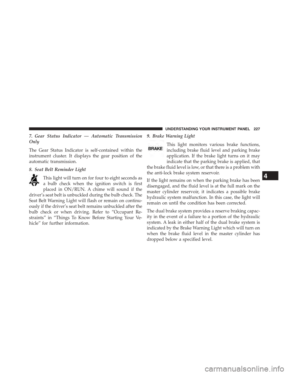
9. Brake Warning Light
This light monitors various brake functions,
including brake fluid level and parking brake
application. If the brake light turns on it may
indicate that the parking brake is applied, that
the brake fluid level is low, or that there is a problem with
the anti-lock brake system reservoir.
If the light remains on when the parking brake has been
disengaged, and the fluid level is at the full mark on the
master cylinder reservoir, it indicates a possible brake
hydraulic system malfunction. In this case, the light will
remain on until the condition has been corrected.
The dual brake system provides a reserve braking capac-
ity in the event of a failure to a portion of the hydraulic
system. A leak in either half of the dual brake system is
indicated by the Brake Warning Light which will turn on
when the brake fluid level in the master cylinder has
dropped below a specified level.
4
UNDERSTANDING YOUR INSTRUMENT PANEL 227
Page 230 of 603
The light will remain on until the cause is corrected.
NOTE:The light may flash momentarily during sharp
cornering maneuvers which change fluid level condi-
tions. The vehicle should have service performed, and
the brake fluid level checked.
If brake failure is indicated, immediate repair is neces-
sary.
WARNING!
Driving a vehicle with the brake light on is danger-
ous. Part of the brake system may have failed. It will
take longer to stop the vehicle. You could have a
collision. Have the vehicle checked immediately.
Vehicles equipped with the Anti-Lock Brake System
(ABS), are also equipped with Electronic Brake Force
Distribution (EBD). In the event of an EBD failure, the
Brake Warning Light will turn on along with the ABS
Light. Immediate repair to the ABS system is required.
Operation of the Brake Warning Light can be checked by
turning the ignition switch from the OFF position to the
ON/RUN position. The light should illuminate for ap-
proximately two seconds. The light should then turn off
unless the parking brake is applied or a brake fault is
detected. If the light does not illuminate, have the light
inspected by an authorized dealer.
The light also will turn on when the parking brake is
applied with the ignition switch in the ON/RUN posi-
tion.
NOTE:This light shows only that the parking brake is
applied. It does not show the degree of brake application.
228 UNDERSTANDING YOUR INSTRUMENT PANEL
Page 246 of 603
Braking Distance
When selected, this screen displays the vehicle’s braking
distance and the speed at which the brake pedal was
depressed.
•This feature will only function when applying the
brakes at speeds above 30 mph (48 km/h).
•Engaging the parking brake will disable this feature.
•The word “READY” will display when conditions are
met for the event to begin.
•The distance and speed measurements display while
the event is taking place.
•The distance measurement will be aborted if the brake
pedal is released before the vehicle comes to a com-
plete stop.
•The distance and speed measurements will continue to
display until theOKbutton is pushed.
•Pushing theOKbutton will clear the current run and
prepare the cluster to record a new run.
Current G-Force
When selected, this screen displays the current G-Force
(lateral and longitudinal) that displays the directions of
the forces.
Peak G-Force
When selected, this screen displays all four G-Force
values (two lateral and two longitudinal).
•When a force greater than zero is measured, the
display will update the value as it climbs. As the
G-Force falls, the peak forces will continue to display.
•Pushing theOKbutton will clear the peak force
values.
244 UNDERSTANDING YOUR INSTRUMENT PANEL