DODGE CHALLENGER 2015 3.G User Guide
Manufacturer: DODGE, Model Year: 2015, Model line: CHALLENGER, Model: DODGE CHALLENGER 2015 3.GPages: 220, PDF Size: 30.96 MB
Page 151 of 220
CAUTION!
Continuous driving with the Transmission Temperature Warning Light illuminated will
eventually cause severe transmission damage or transmission failure.
WARNING!
If you continue operating the vehicle when the Transmission Temperature Warning
Light is illuminated you could cause the fluid to boil over, come in contact with hot
engine or exhaust components and cause a fire.
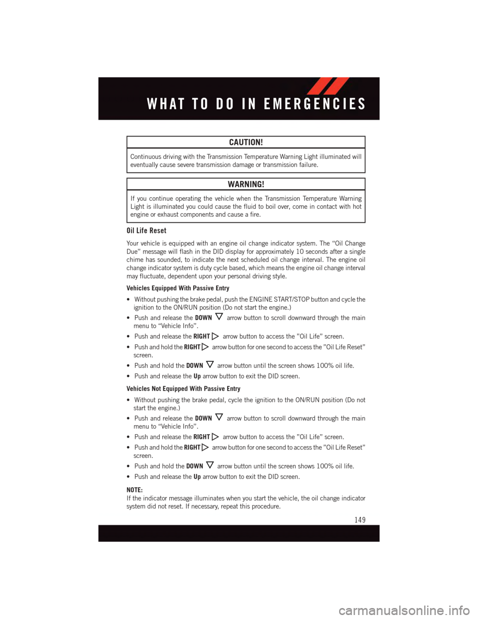
Oil Life Reset
Yo u r v e h i c l e i s e q u i p p e d w i t h a n e n g i n e o i l c h a n g e i n d i c a t o r s y s t e m . T h e “ O i l C h a n g e
Due” message will flash in the DID display for approximately 10 seconds after a single
chime has sounded, to indicate the next scheduled oil change interval. The engine oil
change indicator system is duty cycle based, which means the engine oil change interval
may fluctuate, dependent upon your personal driving style.
Vehicles Equipped With Passive Entry
•Withoutpushingthebrakepedal,pushtheENGINESTART/STOPbuttonandcyclethe
ignition to the ON/RUN position (Do not start the engine.)
•PushandreleasetheDOWNarrow button to scroll downward through the main
menu to “Vehicle Info”.
•PushandreleasetheRIGHTarrow button to access the ”Oil Life” screen.
•PushandholdtheRIGHTarrow button for one second to access the ”Oil Life Reset”
screen.
•PushandholdtheDOWNarrow button until the screen shows 100% oil life.
•PushandreleasetheUparrow button to exit the DID screen.
Vehicles Not Equipped With Passive Entry
•Withoutpushingthebrakepedal,cycletheignitiontotheON/RUNposition(Donot
start the engine.)
•PushandreleasetheDOWNarrow button to scroll downward through the main
menu to “Vehicle Info”.
•PushandreleasetheRIGHTarrow button to access the ”Oil Life” screen.
•PushandholdtheRIGHTarrow button for one second to access the ”Oil Life Reset”
screen.
•PushandholdtheDOWNarrow button until the screen shows 100% oil life.
•PushandreleasetheUparrow button to exit the DID screen.
NOTE:
If the indicator message illuminates when you start the vehicle, the oil change indicator
system did not reset. If necessary, repeat this procedure.
WHAT TO DO IN EMERGENCIES
149
Page 152 of 220
Resetting The Light After Servicing
Vehicles Equipped With Keyless Enter-N-Go™
1. Without pressing the brake pedal, push the ENGINE START/STOP button and cycle
the ignition to the ON/RUN position (do not start the engine.)
2. Fully depress the accelerator pedal, slowly, three times within 10 seconds.
3. Without pressing the brake pedal, push the ENGINE START/STOP button once to
return the ignition to the OFF/LOCK position.
Vehicles Not Equipped With Keyless Enter-N-Go™
1. Turn the ignition switch to the ON/RUN position (do not start the engine.)
2. Fully depress the accelerator pedal, slowly, three times within 10 seconds.
3. Turn the ignition switch to the OFF/LOCK position.
NOTE:
If the indicator message illuminates when you start the vehicle, the oil change indicator
system did not reset. If necessary, repeat this procedure.
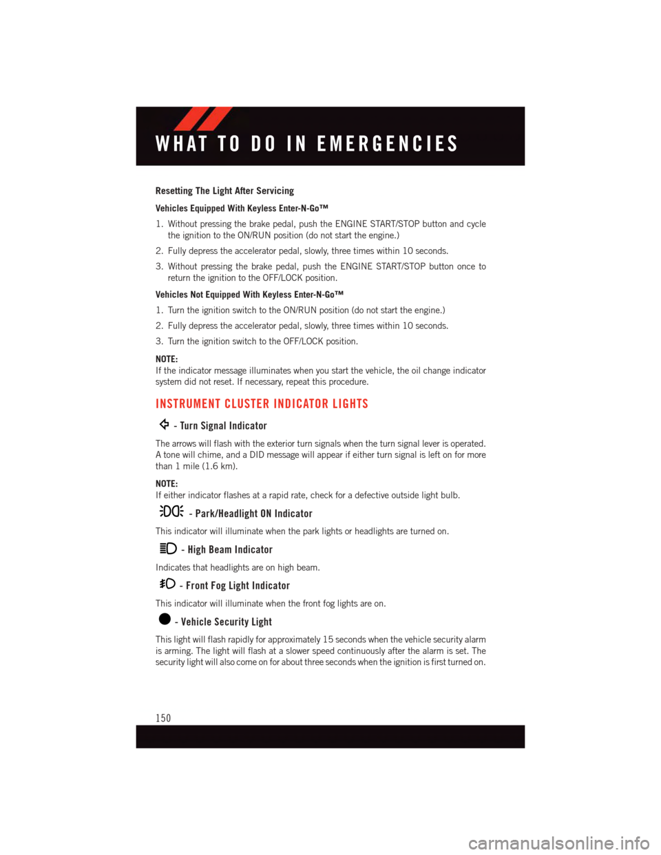
INSTRUMENT CLUSTER INDICATOR LIGHTS
-TurnSignalIndicator
The arrows will flash with the exterior turn signals when the turn signal lever is operated.
Atonewillchime,andaDIDmessagewillappearifeitherturnsignalisleftonformore
than 1 mile (1.6 km).
NOTE:
If either indicator flashes at a rapid rate, check for a defective outside light bulb.
-Park/HeadlightONIndicator
This indicator will illuminate when the park lights or headlights are turned on.
-HighBeamIndicator
Indicates that headlights are on high beam.
-FrontFogLightIndicator
This indicator will illuminate when the front fog lights are on.
-VehicleSecurityLight
This light will flash rapidly for approximately 15 seconds when the vehicle security alarm
is arming. The light will flash at a slower speed continuously after the alarm is set. The
security light will also come on for about three seconds when the ignition is first turned on.
WHAT TO DO IN EMERGENCIES
150
Page 153 of 220
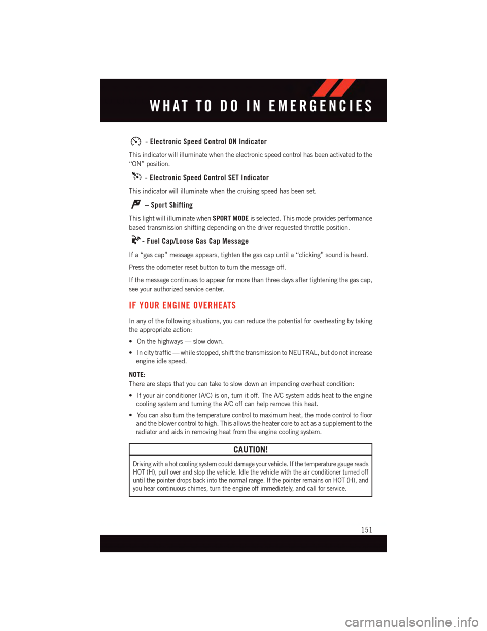
-ElectronicSpeedControlONIndicator
This indicator will illuminate when the electronic speed control has been activated to the
“ON” position.
-ElectronicSpeedControlSETIndicator
This indicator will illuminate when the cruising speed has been set.
–SportShifting
This light will illuminate whenSPORT MODEis selected. This mode provides performance
based transmission shifting depending on the driver requested throttle position.
-FuelCap/LooseGasCapMessage
If a “gas cap” message appears, tighten the gas cap until a “clicking” sound is heard.
Press the odometer reset button to turn the message off.
If the message continues to appear for more than three days after tightening the gas cap,
see your authorized service center.
IF YOUR ENGINE OVERHEATS
In any of the following situations, you can reduce the potential for overheating by taking
the appropriate action:
•Onthehighways—slowdown.
•Incitytraffic—whilestopped,shiftthetransmissiontoNEUTRAL,butdonotincrease
engine idle speed.
NOTE:
There are steps that you can take to slow down an impending overheat condition:
•Ifyourairconditioner(A/C)ison,turnitoff.TheA/Csystemaddsheattotheengine
cooling system and turning the A/C off can help remove this heat.
•Youcanalsoturnthetemperaturecontroltomaximumheat,themodecontroltofloor
and the blower control to high. This allows the heater core to act as a supplement to the
radiator and aids in removing heat from the engine cooling system.
CAUTION!
Driving with a hot cooling system could damage your vehicle. If the temperature gauge reads
HOT (H), pull over and stop the vehicle. Idle the vehicle with the air conditioner turned off
until the pointer drops back into the normal range. If the pointer remains on HOT (H), and
you hear continuous chimes, turn the engine off immediately, and call for service.
WHAT TO DO IN EMERGENCIES
151
Page 154 of 220
WARNING!
Yo u o r o t h e r s c a n b e b a d l y b u r n e d b y h o t e n g i n e c o o l a n t ( a n t i f r e e z e ) o r s t e a m f r o m y o u r
radiator. If you see or hear steam coming from under the hood, do not open the hood
until the radiator has had time to cool. Never try to open a cooling system pressure cap
when the radiator or coolant bottle is hot.
JACKING AND TIRE CHANGING
Jack Location/Spare Tire Stowage
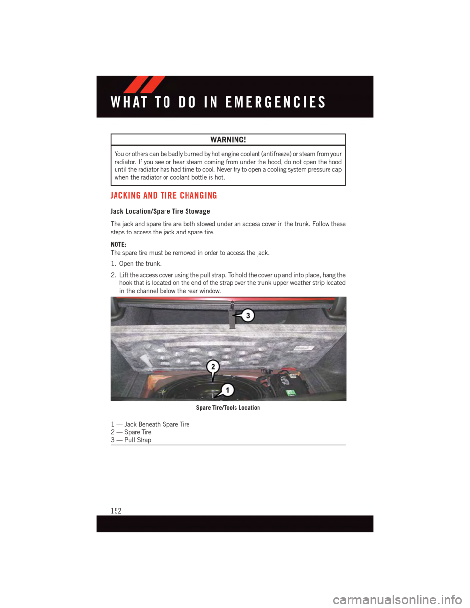
The jack and spare tire are both stowed under an access cover in the trunk. Follow these
steps to access the jack and spare tire.
NOTE:
The spare tire must be removed in order to access the jack.
1. Open the trunk.
2. Lift the access cover using the pull strap. To hold the cover up and into place, hang the
hook that is located on the end of the strap over the trunk upper weather strip located
in the channel below the rear window.
1—JackBeneathSpareTire2—SpareTire3—PullStrap
Spare Tire/Tools Location
WHAT TO DO IN EMERGENCIES
152
Page 155 of 220
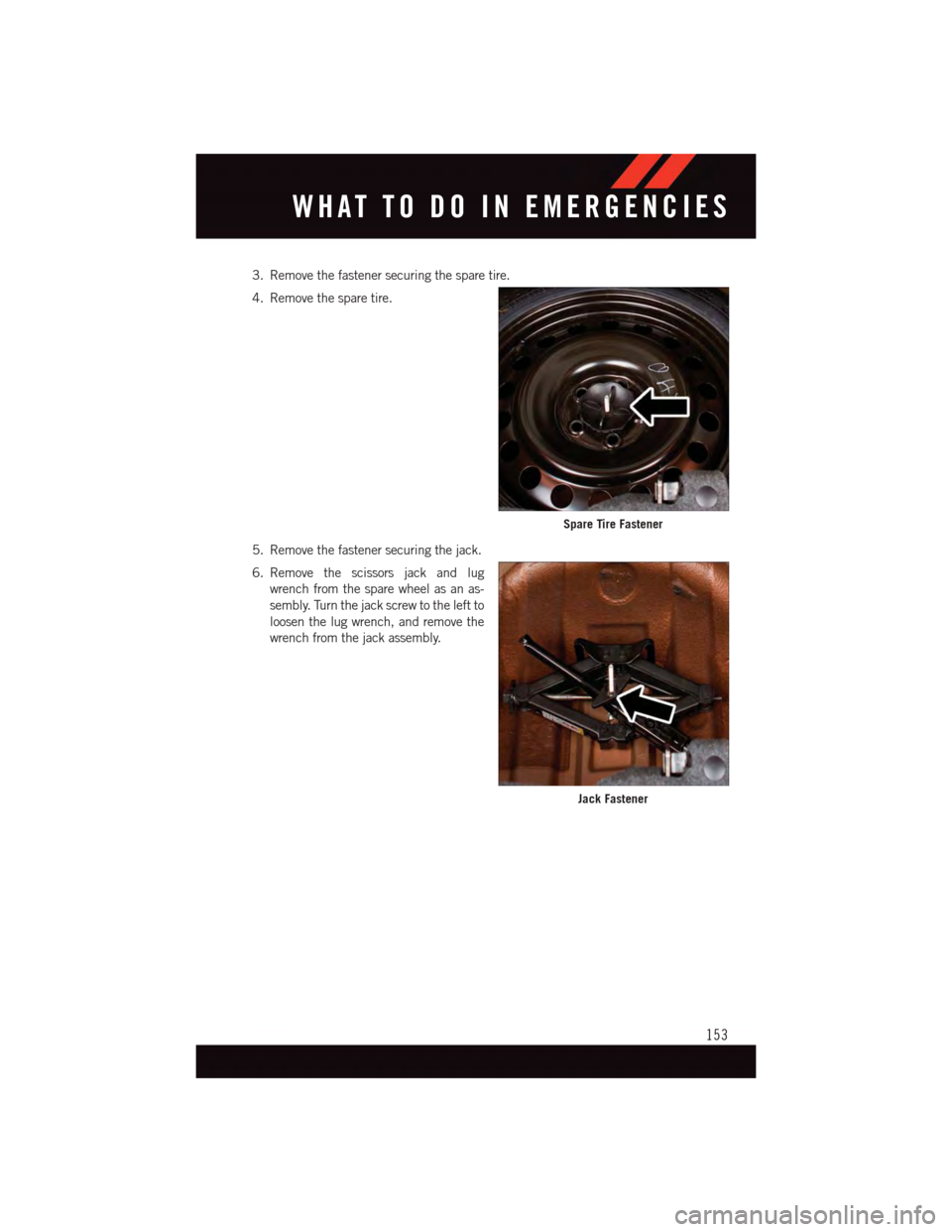
3. Remove the fastener securing the spare tire.
4. Remove the spare tire.
5. Remove the fastener securing the jack.
6. Remove the scissors jack and lug
wrench from the spare wheel as an as-
sembly. Turn the jack screw to the left to
loosen the lug wrench, and remove the
wrench from the jack assembly.
Spare Tire Fastener
Jack Fastener
WHAT TO DO IN EMERGENCIES
153
Page 156 of 220
Preparations For Jacking
1. Park the vehicle on a firm, level surface as far from the edge of the roadway as possible.
Avoid icy or slippery areas.
2. Turn on the Hazard Warning flasher.
3. Set the parking brake.
4. Place the shift lever into PARK.
5. Turn OFF the ignition.
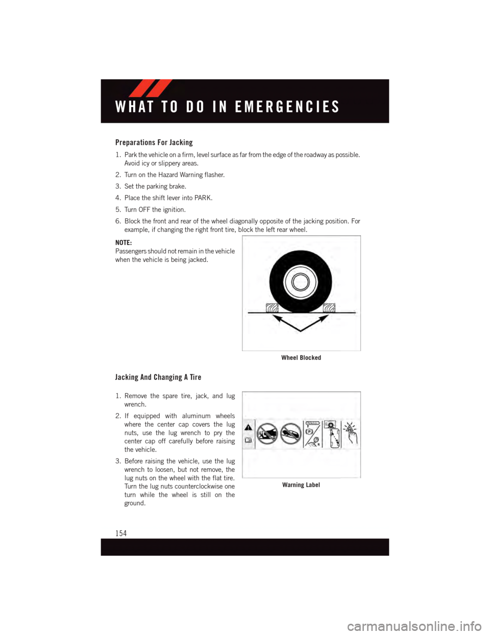
6. Block the front and rear of the wheel diagonally opposite of the jacking position. For
example, if changing the right front tire, block the left rear wheel.
NOTE:
Passengers should not remain in the vehicle
when the vehicle is being jacked.
Jacking And Changing A Tire
1. Remove the spare tire, jack, and lug
wrench.
2. If equipped with aluminum wheels
where the center cap covers the lug
nuts, use the lug wrench to pry the
center cap off carefully before raising
the vehicle.
3. Before raising the vehicle, use the lug
wrench to loosen, but not remove, the
lug nuts on the wheel with the flat tire.
Tu r n t h e l u g n u t s c o u n t e r c l o c k w i s e o n e
turn while the wheel is still on the
ground.
Wheel Blocked
Warning Label
WHAT TO DO IN EMERGENCIES
154
Page 157 of 220
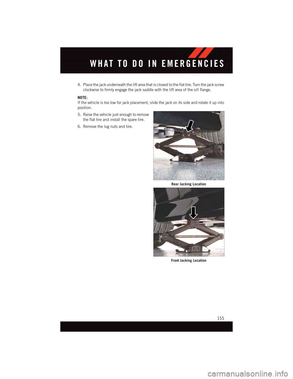
4. Place the jack underneath the lift area that is closest to the flat tire. Turn the jack screw
clockwise to firmly engage the jack saddle with the lift area of the sill flange.
NOTE:
If the vehicle is too low for jack placement, slide the jack on its side and rotate it up into
position.
5. Raise the vehicle just enough to remove
the flat tire and install the spare tire.
6. Remove the lug nuts and tire.
Rear Jacking Location
Front Jacking Location
WHAT TO DO IN EMERGENCIES
155
Page 158 of 220
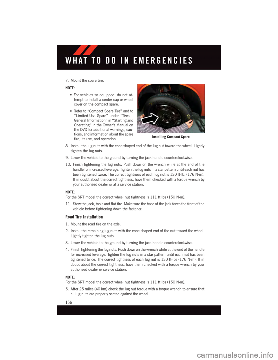
7. Mount the spare tire.
NOTE:
•Forvehiclessoequipped,donotat-
tempt to install a center cap or wheel
cover on the compact spare.
•Referto“CompactSpareTire”andto
“Limited-Use Spare” under “Tires—
General Information” in “Starting and
Operating” in the Owner's Manual on
the DVD for additional warnings, cau-
tions, and information about the spare
tire, its use, and operation.
8. Install the lug nuts with the cone shaped end of the lug nut toward the wheel. Lightly
tighten the lug nuts.
9. Lower the vehicle to the ground by turning the jack handle counterclockwise.
10. Finish tightening the lug nuts. Push down on the wrench while at the end of the
handle for increased leverage. Tighten the lug nuts in a star pattern until each nut has
been tightened twice. The correct tightness of each lug nut is 130 ft-lb. (176 N·m).
If in doubt about the correct tightness, have them checked with a torque wrench by
your authorized dealer or at a service station.
NOTE:
For the SRT model the correct wheel nut tightness is 111 ft lbs (150 N·m).
11. Stow the jack, tools and flat tire. Make sure the base of the jack faces the front of the
vehicle before tightening down the fastener.
Road Tire Installation
1. Mount the road tire on the axle.
2. Install the remaining lug nuts with the cone shaped end of the nut toward the wheel.
Lightly tighten the lug nuts.
3. Lower the vehicle to the ground by turning the jack handle counterclockwise.
4. Finish tightening the lug nuts. Push down on the wrench while at the end of the handle
for increased leverage. Tighten the lug nuts in a star pattern until each nut has been
tightened twice. The correct tightness of each lug nut is 130 ft-lbs (176 N·m). If in
doubt about the correct tightness, have them checked with a torque wrench by your
authorized dealer or service station.
NOTE:
For the SRT model the correct wheel nut tightness is 111 ft lbs (150 N·m).
5. After 25 miles (40 km) check the lug nut torque with a torque wrench to ensure that
all lug nuts are properly seated against the wheel.
Installing Compact Spare
WHAT TO DO IN EMERGENCIES
156
Page 159 of 220
CAUTION!
Do not attempt to raise the vehicle by jacking on locations other than those indicated
in the Jacking Instructions for this vehicle.
WARNING!
•Donotattempttochangeatireonthesideofthevehicleclosetomovingtraffic.
Pull far enough off the road to avoid the danger of being hit when operating the jack
or changing the wheel.
•Beingunderajacked-upvehicleisdangerous.Thevehiclecouldslipoffthejack
and fall on you. You could be crushed. Never put any part of your body under a
vehicle that is on a jack.
•Neverstartorruntheenginewhilethevehicleisonajack.Ifyouneedtogetunder
araisedvehicle,takeittoaservicecenterwhereitcanberaisedonalift.
•Thejackisdesignedtobeusedasatoolforchangingtiresonly.Thejackshouldnot
be used to lift the vehicle for service purposes. The vehicle should be jacked on a
firm level surface only. Avoid ice or slippery areas.
•Aloosetireorjackthrownforwardinacollisionorhardstopcouldendangertheoccupants
of the vehicle. Always stow the jack parts and the spare tire in the places provided.
•Carefullyfollowthesetirechangingwarningstohelppreventpersonalinjuryor
damage to your vehicle:
•Alwaysparkonafirm,levelsurfaceasfarfromtheedgeoftheroadwayaspossible
before raising the vehicle.
•TurnontheHazardWarningflasher.
•Blockthewheeldiagonallyoppositethewheeltoberaised.
•SettheparkingbrakefirmlyandsetanautomatictransmissioninPARK;amanual
transmission in REVERSE.
•Donotletanyonesitinthevehiclewhenitisonajack.
•Donotgetunderthevehiclewhenitisonajack.
•Only use the jack in the positions indicated and for lifting this vehicle during a tire change.
•Ifworkingonorneararoadway,beextremelycarefulofmotortraffic.
•Raising the vehicle higher than necessary can make the vehicle less stable. It could slip
off the jack and hurt someone near it. Raise the vehicle only enough to remove the tire.
•Toavoidtheriskofforcingthevehicleoffthejack,donotfullytightenthewheel
nuts until the vehicle has been lowered. Failure to follow this warning may result in
personal injury.
•Aloosetireorjackthrownforwardinacollisionorhardstopcouldendangertheoccupants
of the vehicle. Always stow the jack parts and the spare tire in the places provided.
•Thelimited-usesparetiresareforemergencyuseonly.Installationofthislimited-use spare tire affects vehicle handling. With this tire, do not drive more than60 mph (100 km/h). Keep inflated to the cold tire inflation pressure listed on eitheryour tire placard or limited-use spare tire and wheel assembly. Replace (or repair)the original tire at the first opportunity and reinstall it on your vehicle. Failure to doso could result in loss of vehicle control.
WHAT TO DO IN EMERGENCIES
157
Page 160 of 220
TIRE SERVICE KIT
Yo u r v e h i c l e m a y b e e q u i p p e d w i t h a Ti r e S e r v i c e K i t .
Small punctures up to 1/4” (6 mm) in the tire tread can be sealed with the Tire Service Kit.
Foreign objects (e.g., screws or nails) should not be removed from the tire. The Tire Service
Kit can be used in outside temperatures down to approximately -4°F (-20°C).
This kit will provide a temporary tire seal, allowing you to drive your vehicle up to 100
miles (160 km) with a maximum speed of 55 mph (90 km/h).
Tire Service Kit Storage
•TheTireServiceKitislocatedinthetrunk.
Tire Service Kit Components And Operation
Using The Mode Select Knob And Hoses
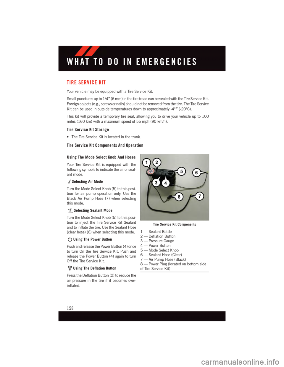
Yo u r Ti r e S e r v i c e K i t i s e q u i p p e d w i t h t h e
following symbols to indicate the air or seal-
ant mode.
Selecting Air Mode
Tu r n t h e M o d e S e l e c t K n o b ( 5 ) t o t h i s p o s i -
tion for air pump operation only. Use the
Black Air Pump Hose (7) when selecting
this mode.
Selecting Sealant Mode
Tu r n t h e M o d e S e l e c t K n o b ( 5 ) t o t h i s p o s i -
tion to inject the Tire Service Kit Sealant
and to inflate the tire. Use the Sealant Hose
(clear hose) (6) when selecting this mode.
Using The Power Button
Push and release the Power Button (4) once
to turn On the Tire Service Kit. Push and
release the Power Button (4) again to turn
Off the Tire Service Kit.
Using The Deflation Button
Press the Deflation Button (2) to reduce the
air pressure in the tire if it becomes over-
inflated.
Tire Service Kit Components
1—SealantBottle2—DeflationButton3—PressureGauge4—PowerButton5—ModeSelectKnob6—SealantHose(Clear)7—AirPumpHose(Black)8—PowerPlug(locatedonbottomsideof Tire Service Kit)
WHAT TO DO IN EMERGENCIES
158