run flat DODGE CHALLENGER 2019 Owners Manual
[x] Cancel search | Manufacturer: DODGE, Model Year: 2019, Model line: CHALLENGER, Model: DODGE CHALLENGER 2019Pages: 532, PDF Size: 5.01 MB
Page 24 of 532
NOTE:
•The interior lights will turn off if you place the ignition
in the ACC or ON/RUN position while the Panic Alarm
is activated. However, the exterior lights and horn will
remain on.
• You may need to be less than 35 ft (11 m) from the
vehicle when using the key fob to turn off the Panic
Alarm due to the radio frequency noises emitted by the
system.
Key Fob Battery Replacement
The recommended replacement battery is one CR2032
battery.
NOTE:
• Perchlorate Material — special handling may apply. See
www.dtsc.ca.gov/hazardouswaste/perchlorate for fur-
ther information.
• Do not touch the battery terminals that are on the back
housing or the printed circuit board.
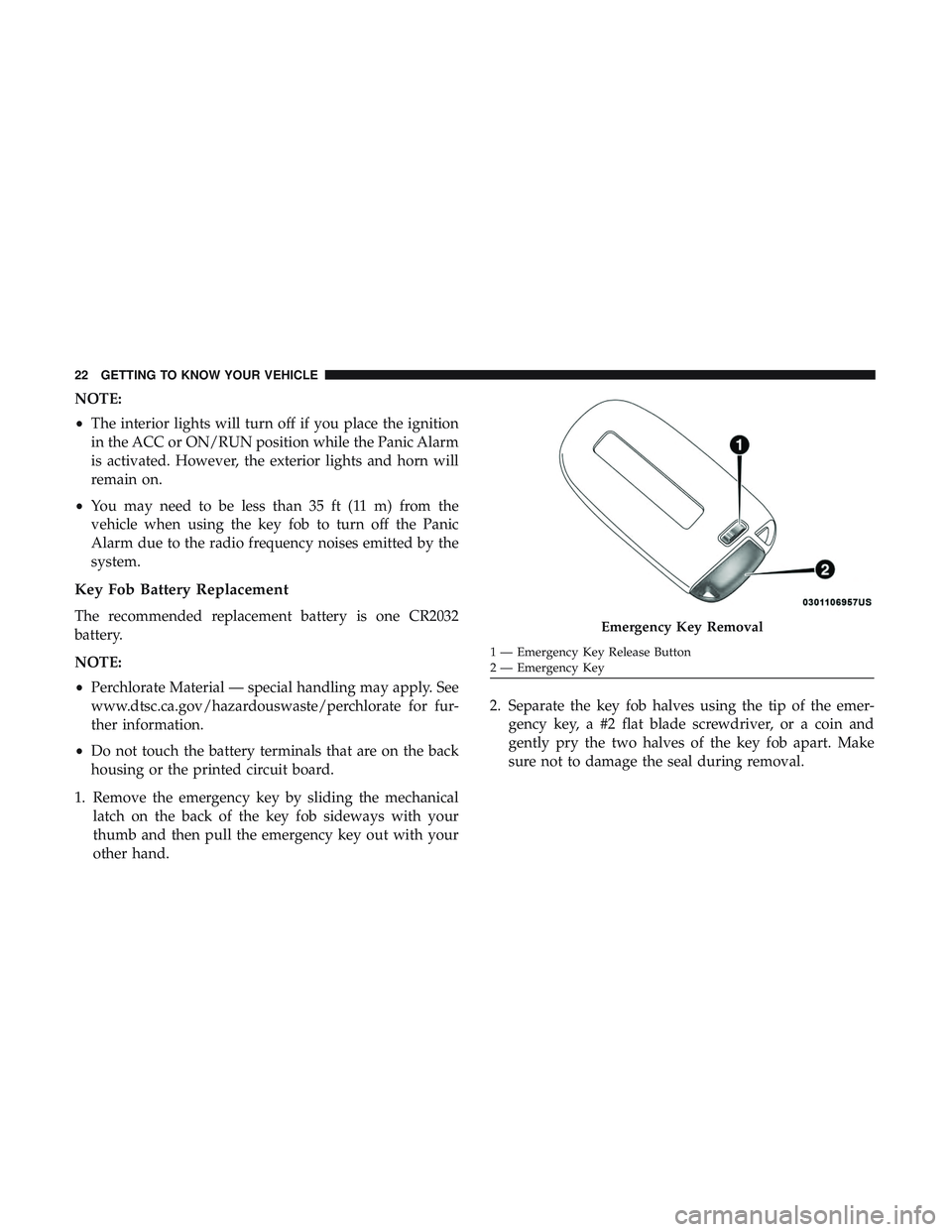
1. Remove the emergency key by sliding the mechanical latch on the back of the key fob sideways with your
thumb and then pull the emergency key out with your
other hand. 2. Separate the key fob halves using the tip of the emer-
gency key, a #2 flat blade screwdriver, or a coin and
gently pry the two halves of the key fob apart. Make
sure not to damage the seal during removal.Emergency Key Removal
1 — Emergency Key Release Button
2 — Emergency Key
22 GETTING TO KNOW YOUR VEHICLE
Page 111 of 532
If one or more tires have low pressure, “Inflate Tire To XX”
is displayed with the vehicle ICON and the tire pressure
values in each corner of the ICON with the pressure value
of the low tire are displayed in a different color than the
other tire pressure value.
If the Tire Pressure system requires service, “Service Tire
Pressure System” is displayed.
Tire PSI is an information only function and cannot be
reset. Refer to “Tire Pressure Monitoring System (TPMS)”
under “Safety” for further information.
Coolant Temp
•Displays the actual coolant temperature.
Trans Temp
• Displays the actual transmission temperature.
Oil Temp
• Displays the actual oil temperature.
Oil Pressure
• Displays the actual oil pressure. Oil Life
To reset the Oil Life, you must hold the OK button. The
“Hold OK to Reset” instruction will be displayed at all
times, but the following conditions will need to be met in
order to reset Oil Life:
•
The vehicle must be off
• The ignition must be in the ON/RUN position
If the conditions are met, holding the OKbutton will reset
the gauge and the numeric display will return to 100%.
If the conditions are not met, a popup message will display
for 5 seconds, describing the required conditions, and then
the Oil Life screen will reappear.
Battery Voltage
• Displays the actual battery voltage.
Driver Assist — If Equipped
Adaptive Cruise Control (ACC) Menu
The instrument cluster display displays the current ACC
system settings. The information displayed depends on
ACC system status.
4
GETTING TO KNOW YOUR INSTRUMENT PANEL 109
Page 170 of 532
•Instrument Panel
• Knee Impact Bolsters
• Driver and Front Passenger Air Bags
• Seat Belt Buckle Switch
• Supplemental Side Air Bags
• Front and Side Impact Sensors
• Seat Belt Pretensioners
• Seat Track Position Sensors
Non-SRT Vehicles
NOTE: Vehicles with front passenger seat deleted will not
be equipped with the Seat Belt Buckle Switch, Seat Belt
Pretensioner, Supplemental Seat Mounted Side Airbag, and
Seat Track Position Sensors for the front passenger.
If the passenger and/or rear seats have been removed do
not ride in those areas.
All passenger occupants within the vehicle must be in a
seat equipped with a Seat Belt System and Head Restraint
for the safety of the passenger.Air Bag Warning Light
The ORC monitors the readiness of the electronic
parts of the air bag system whenever the ignition
switch is in the START or ON/RUN position. If
the ignition switch is in the OFF position or in the
ACC position, the air bag system is not on and the air bags
will not inflate.
The ORC contains a backup power supply system that may
deploy the air bag system even if the battery loses power or
it becomes disconnected prior to deployment.
The ORC turns on the Air Bag Warning Light in the
instrument panel for approximately four to eight seconds
for a self-check when the ignition switch is first in the
ON/RUN position. After the self-check, the Air Bag Warn-
ing Light will turn off. If the ORC detects a malfunction in
any part of the system, it turns on the Air Bag Warning
Light, either momentarily or continuously. A single chime
will sound to alert you if the light comes on again after
initial startup.
The ORC also includes diagnostics that will illuminate the
instrument panel Air Bag Warning Light if a malfunction is
detected that could affect the air bag system. The diagnos-
tics also record the nature of the malfunction. While the air
168 SAFETY
Page 171 of 532
bag system is designed to be maintenance free, if any of the
following occurs, have an authorized dealer service the air
bag system immediately.
•The Air Bag Warning Light does not come on during the
four to eight seconds when the ignition switch is first in
the ON/RUN position.
• The Air Bag Warning Light remains on after the four to
eight-second interval.
• The Air Bag Warning Light comes on intermittently or
remains on while driving.
NOTE: If the speedometer, tachometer, or any engine
related gauges are not working, the Occupant Restraint
Controller (ORC) may also be disabled. In this condition
the air bags may not be ready to inflate for your protection.
Have an authorized dealer service the air bag system
immediately.
WARNING!
Ignoring the Air Bag Warning Light in your instrument
panel could mean you won’t have the air bag system to
protect you in a collision. If the light does not come on
(Continued)
WARNING! (Continued)
as a bulb check when the ignition is first turned on,
stays on after you start the vehicle, or if it comes on as
you drive, have an authorized dealer service the air bag
system immediately.
Redundant Air Bag Warning Light
If a fault with the Air Bag Warning Light is
detected, which could affect the Supplemental
Restraint System (SRS), the Redundant Air Bag
Warning Light will illuminate on the instrument
panel. The Redundant Air Bag Warning Light will stay on
until the fault is cleared. In addition, a single chime will
sound to alert you that the Redundant Air Bag Warning
Light has come on and a fault has been detected. If the
Redundant Air Bag Warning Light comes on intermittently
or remains on while driving have an authorized dealer
service the vehicle immediately.
For additional information regarding the Redundant Air
Bag Warning Light refer to “Getting To Know Your Instru-
ment Panel” section of this manual.5
SAFETY 169
Page 181 of 532
•Front wiper
• Headlamp washer pump
NOTE: After an accident, remember to cycle the ignition
to the STOP (OFF/LOCK) position and remove the key
from the ignition switch to avoid draining the battery.
Carefully check the vehicle for fuel leaks in the engine
compartment and on the ground near the engine compart-
ment and fuel tank before resetting the system and starting
the engine. If there are no fuel leaks or damage to the
vehicle electrical devices (e.g. headlights) after an accident,
reset the system by following the procedure described
below. If you have any doubt, contact an authorized dealer.
Enhanced Accident Response System Reset
Procedure
In order to reset the Enhanced Accident Response System
functions after an event, the ignition switch must be
changed from ignition START or ON/RUN to ignition OFF.
Carefully check the vehicle for fuel leaks in the engine
compartment and on the ground near the engine compart-
ment and fuel tank before resetting the system and starting
the engine.
Maintaining Your Air Bag System
WARNING!
• Modifications to any part of the air bag system could
cause it to fail when you need it. You could be
injured if the air bag system is not there to protect
you. Do not modify the components or wiring, in-
cluding adding any kind of badges or stickers to the
steering wheel hub trim cover or the upper passenger
side of the instrument panel. Do not modify the front
bumper, vehicle body structure, or add aftermarket
side steps or running boards.
• It is dangerous to try to repair any part of the air bag
system yourself. Be sure to tell anyone who works on
your vehicle that it has an air bag system.
• Do not attempt to modify any part of your air bag
system. The air bag may inflate accidentally or may
not function properly if modifications are made.
Take your vehicle to an authorized dealer for any air
bag system service. If your seat, including your trim
cover and cushion, needs to be serviced in any way
(including removal or loosening/tightening of seat
attachment bolts), take the vehicle to an authorized
(Continued)
5
SAFETY 179
Page 279 of 532
•Replace tires when tread wear indicators first become
visible.
• Keep tires properly inflated.
• Maintain sufficient distance between your vehicle and
the vehicle in front of you to avoid a collision in a
sudden stop.
Your vehicle may be equipped with a Limited Slip Differ-
ential (LSD) that reduces, but does not eliminate, the
amount of wheel slip across a given axle for improved
handling.
Driving Through Water
Driving through water more than a few inches/centimeters
deep will require extra caution to ensure safety and pre-
vent damage to your vehicle.
Flowing/Rising Water
WARNING!
Do not drive on or across a road or path where water is
flowing and/or rising (as in storm run-off). Flowing
water can wear away the road or path’s surface and
cause your vehicle to sink into deeper water. Further-
more, flowing and/or rising water can carry your ve-
hicle away swiftly. Failure to follow this warning may
result in injuries that are serious or fatal to you, your
passengers, and others around you.
6
STARTING AND OPERATING 277
Page 311 of 532
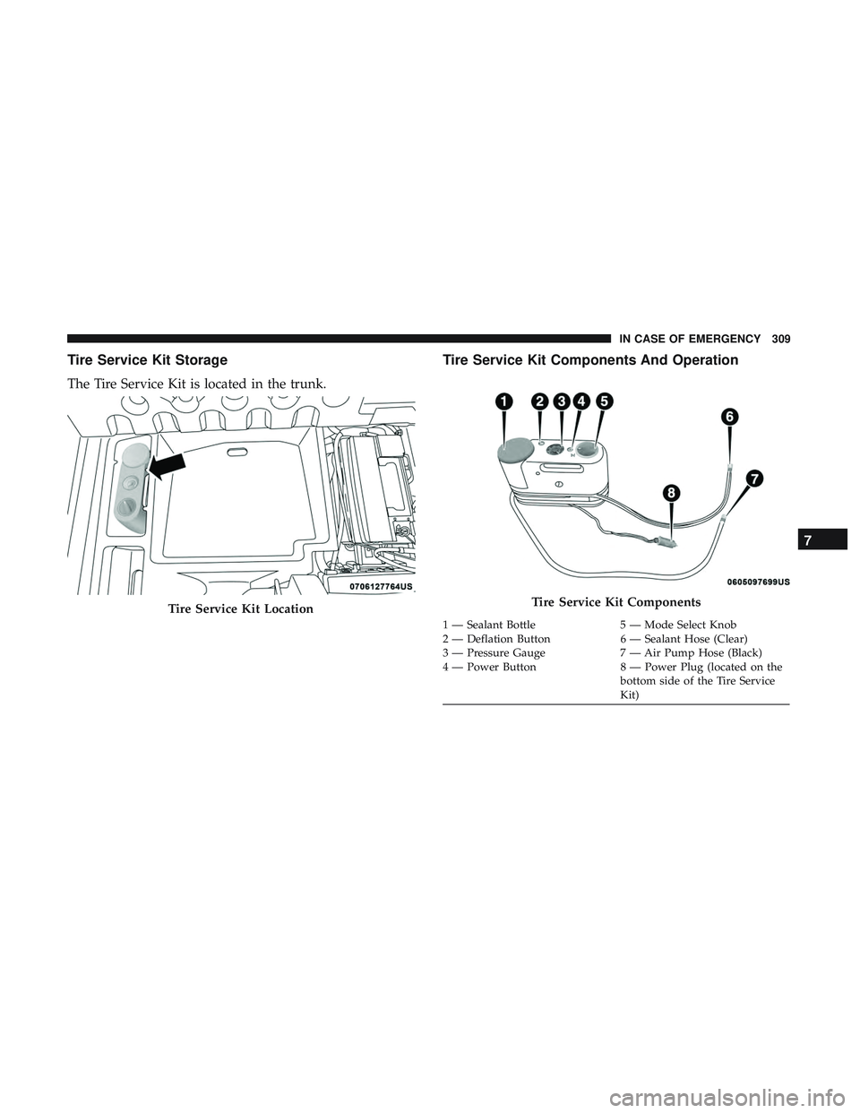
Tire Service Kit Storage
The Tire Service Kit is located in the trunk.
Tire Service Kit Components And Operation
Tire Service Kit LocationTire Service Kit Components
1 — Sealant Bottle5 — Mode Select Knob
2 — Deflation Button 6 — Sealant Hose (Clear)
3 — Pressure Gauge 7 — Air Pump Hose (Black)
4 — Power Button 8 — Power Plug (located on the
bottom side of the Tire Service
Kit)
7
IN CASE OF EMERGENCY 309
Page 314 of 532
WARNING!(Continued)
in injuries that are serious or fatal to you, your
passengers, and others around you.
• Take care not to allow the contents of Tire Service Kit
to come in contact with hair, eyes, or clothing. Tire
Service Kit sealant is harmful if inhaled, swallowed,
or absorbed through the skin. It causes skin, eye, and
respiratory irritation. Flush immediately with plenty
of water if there is any contact with eyes or skin.
Change clothing as soon as possible, if there is any
contact with clothing.
• Tire Service Kit Sealant solution contains latex. In
case of an allergic reaction or rash, consult a physi-
cian immediately. Keep Tire Service Kit out of reach
of children. If swallowed, rinse mouth immediately
with plenty of water and drink plenty of water. Do
not induce vomiting! Consult a physician immedi-
ately.
Sealing A Tire With Tire Service Kit
(A) Whenever You Stop To Use Tire Service Kit:
1. Pull over to a safe location and turn on the vehicle’s Hazard Warning flashers. 2. Verify that the valve stem (on the wheel with the
deflated tire) is in a position that is near to the ground.
This will allow the Tire Service Kit Hoses (6) and (7) to
reach the valve stem and keep the Tire Service Kit flat on
the ground. This will provide the best positioning of the
kit when injecting the sealant into the deflated tire and
running the air pump. Move the vehicle as necessary to
place the valve stem in this position before proceeding.
3. Place the transmission in PARK (auto transmission) or in Gear (manual transmission) and place the ignition in the
OFF position.
4. Apply the parking brake.
(B) Setting Up To Use Tire Service Kit:
1. Push in the Mode Select Knob (5) and turn to the Sealant Mode position.
2. Uncoil the Sealant Hose (6) and then remove the cap from the fitting at the end of the hose.
3. Place the Tire Service Kit flat on the ground next to the deflated tire.
4. Remove the cap from the valve stem and then screw the fitting at the end of the Sealant Hose (6) onto the valve
stem.
312 IN CASE OF EMERGENCY
Page 315 of 532
5. Uncoil the Power Plug (8) and insert the plug into thevehicle’s 12 Volt power outlet.
NOTE: Do not remove foreign objects (e.g., screws or
nails) from the tire.
(C) Injecting Tire Service Kit Sealant Into The
Deflated Tire:
• Always start the engine before turning ON the Tire
Service Kit.
NOTE: Manual transmission vehicles must have the park-
ing brake engaged and the gear selector in NEUTRAL.
• After pushing the Power Button (4), the sealant (white
fluid) will flow from the Sealant Bottle (1) through the
Sealant Hose (6) and into the tire.
NOTE: Sealant may leak out through the puncture in the
tire.
If the sealant (white fluid) does not flow within0–10
seconds through the Sealant Hose (6):
1. Push the Power Button (4) to turn Off the Tire Service Kit. Disconnect the Sealant Hose (6) from the valve stem.
Make sure the valve stem is free of debris. Reconnect the
Sealant Hose (6) to the valve stem. Check that the Mode Select Knob (5) is in the Sealant Mode position and not
Air Mode. Push the Power Button (4) to turn On the Tire
Service Kit.
2. Connect the Power Plug (8) to a different 12 Volt power outlet in your vehicle or another vehicle, if available.
Make sure the engine is running before turning ON the
Tire Service Kit.
3. The Sealant Bottle (1) may be empty due to previous use. Call for assistance.
NOTE: If the Mode Select Knob (5) is on Air Mode and the
pump is operating, air will dispense from the Air Pump
Hose (7) only, not the Sealant Hose (6).
If the sealant (white fluid) does flow through the Sealant
Hose (6):
1. Continue to operate the pump until sealant is no longer flowing through the hose (typically takes 30 - 70 sec-
onds). As the sealant flows through the Sealant Hose (6),
the Pressure Gauge (3) can read as high as 70 psi
(4.8 Bar). The Pressure Gauge (3) will decrease quickly
from approximately 70 psi (4.8 Bar) to the actual tire
pressure when the Sealant Bottle (1) is empty.
7
IN CASE OF EMERGENCY 313
Page 319 of 532
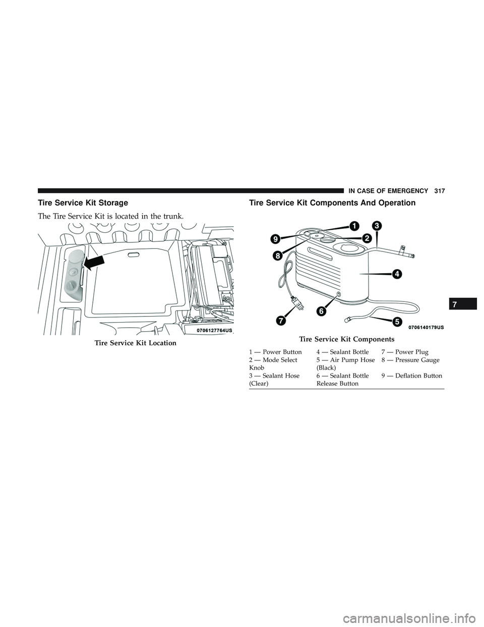
Tire Service Kit Storage
The Tire Service Kit is located in the trunk.
Tire Service Kit Components And Operation
Tire Service Kit LocationTire Service Kit Components
1 — Power Button 4 — Sealant Bottle 7 — Power Plug
2 — Mode Select
Knob5 — Air Pump Hose
(Black)8 — Pressure Gauge
3 — Sealant Hose
(Clear) 6 — Sealant Bottle
Release Button9 — Deflation Button
7
IN CASE OF EMERGENCY 317