DODGE CHALLENGER SRT 2018 Owners Manual
Manufacturer: DODGE, Model Year: 2018, Model line: CHALLENGER SRT, Model: DODGE CHALLENGER SRT 2018Pages: 486, PDF Size: 4.56 MB
Page 291 of 486
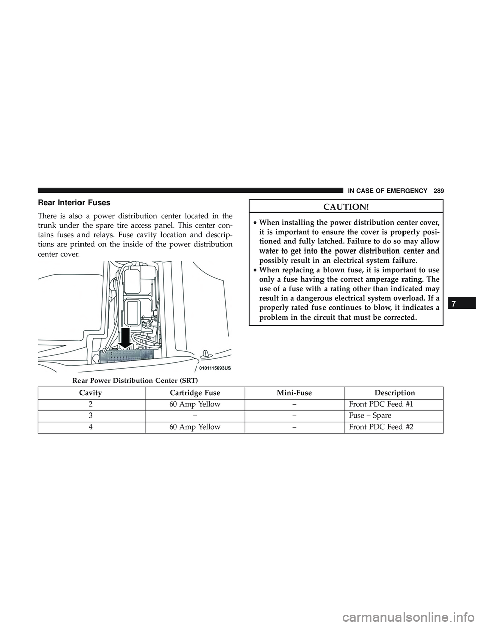
Rear Interior Fuses
There is also a power distribution center located in the
trunk under the spare tire access panel. This center con-
tains fuses and relays. Fuse cavity location and descrip-
tions are printed on the inside of the power distribution
center cover.
CAUTION!
•When installing the power distribution center cover,
it is important to ensure the cover is properly posi-
tioned and fully latched. Failure to do so may allow
water to get into the power distribution center and
possibly result in an electrical system failure.
• When replacing a blown fuse, it is important to use
only a fuse having the correct amperage rating. The
use of a fuse with a rating other than indicated may
result in a dangerous electrical system overload. If a
properly rated fuse continues to blow, it indicates a
problem in the circuit that must be corrected.
Cavity Cartridge Fuse Mini-FuseDescription
2 60 Amp Yellow –Front PDC Feed #1
3 ––Fuse – Spare
4 60 Amp Yellow –Front PDC Feed #2
Rear Power Distribution Center (SRT)
7
IN CASE OF EMERGENCY 289
Page 292 of 486
CavityCartridge Fuse Mini-FuseDescription
5 30 Amp Pink
20 Amp Blue – Police –
Sunroof/Dome Lamp –
Police
6 40 Amp Green –Exterior Lighting #1
7 40 Amp Green –Exterior Lighting #2
8 30 Amp Pink –Interior Lighting
9 40 Amp Green –Power Locks
10 30 Amp Pink –Driver Door Control Mod-
ule
11 30 Amp Pink –Passenger Door Control
Module
12 –20 Amp Yellow Dual USB Center Console
Rear/Cigar Lighter IP – If
Equipped
15 40 Amp Green –HVAC Blower
16 20 Amp Blue –Left Spot Lamp – Police
17 20 Amp Blue –Right Spot Lamp – Police
18 30 Amp Pink –Mod Network Interface –
Police
19 ––Fuse – Spare
20 ––Fuse – Spare
290 IN CASE OF EMERGENCY
Page 293 of 486
CavityCartridge Fuse Mini-FuseDescription
21 30 Amp Pink –Fuel Pump (Non 6.2L SRT
Demon)
22 –5 Amp Tan Cyber Gateway Mod
23 –10 Amp Red Fuel Door/Diagnostic Port
24 –10 Amp Red Integrated Center Stack
25 –10 Amp Red Tire Pressure Monitor
26 –15 Amp Blue Cygnus Transmission
Module (Charger/300) /
Electronic Shift Module
(Charger/300)
27 –25 Amp Clear Amplifier – If Equipped
31 –25 Amp Breaker Power Seats – If Equipped
32 –15 Amp Blue HVAC Module/Cluster
33 –15 Amp Blue Ignition Switch/RF Hub
Module/Steering Column
Lock (300) – If Equipped
34 –10 Amp Red Steering Column Module/
Clock (300)
35 –5 Amp Tan Battery Sensor
36 –15 Amp Blue Electronic Exhaust Valve –
If Equipped
7
IN CASE OF EMERGENCY 291
Page 294 of 486
CavityCartridge Fuse Mini-FuseDescription
37 –20 Amp Yellow Radio
38 –20 Amp Yellow Power Outlet Inside Arm
Rest/Console Media Hub
40 30 Amp Pink –Fuel Pump (6.2L SRT De-
mon – If Equipped)
41 30 Amp Pink –Fuel Pump (6.2L SRT De-
mon – If Equipped)
42 30 Amp Pink –Rear Defrost
43 –20 Amp Yellow Comfort Seat And Steering
Wheel Module (Heated
Steering Wheel/RR
Heated Seats)
44 –10 Amp Red Park Assist / Blind Spot /
Rear View Camera
45 –15 Amp Blue Cluster / Rearview Mirror
/ Compass (Charger/300)
/ Humidity Sensor / For-
ward Facing Camera (Lane
Departure) / Cyber Gate-
way
46 ––Fuse – Spare
292 IN CASE OF EMERGENCY
Page 295 of 486
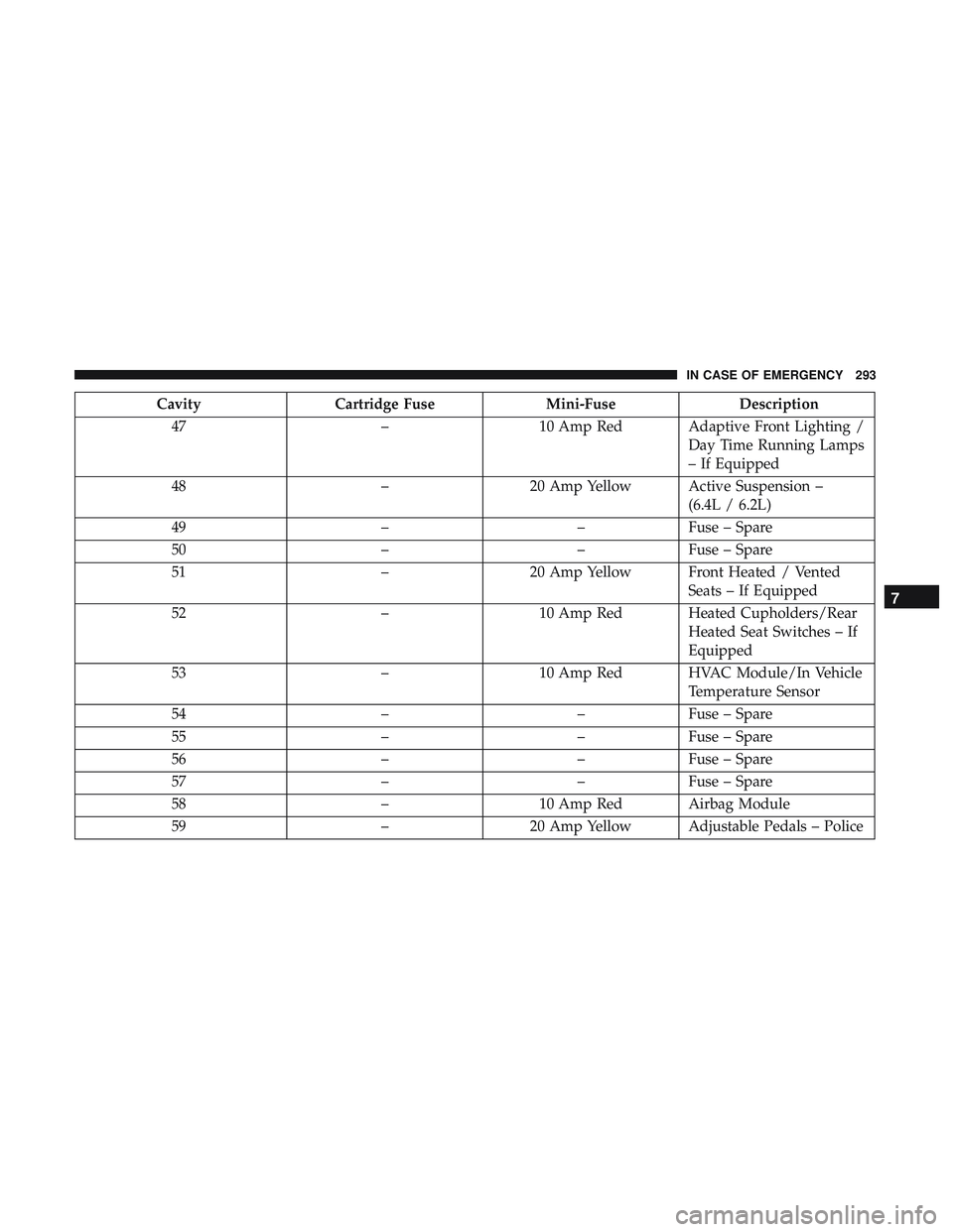
CavityCartridge Fuse Mini-FuseDescription
47 –10 Amp Red Adaptive Front Lighting /
Day Time Running Lamps
– If Equipped
48 –20 Amp Yellow Active Suspension –
(6.4L / 6.2L)
49 ––Fuse – Spare
50 ––Fuse – Spare
51 –20 Amp Yellow Front Heated / Vented
Seats – If Equipped
52 –10 Amp Red Heated Cupholders/Rear
Heated Seat Switches – If
Equipped
53 –10 Amp Red HVAC Module/In Vehicle
Temperature Sensor
54 ––Fuse – Spare
55 ––Fuse – Spare
56 ––Fuse – Spare
57 ––Fuse – Spare
58 –10 Amp Red Airbag Module
59 –20 Amp Yellow Adjustable Pedals – Police
7
IN CASE OF EMERGENCY 293
Page 296 of 486
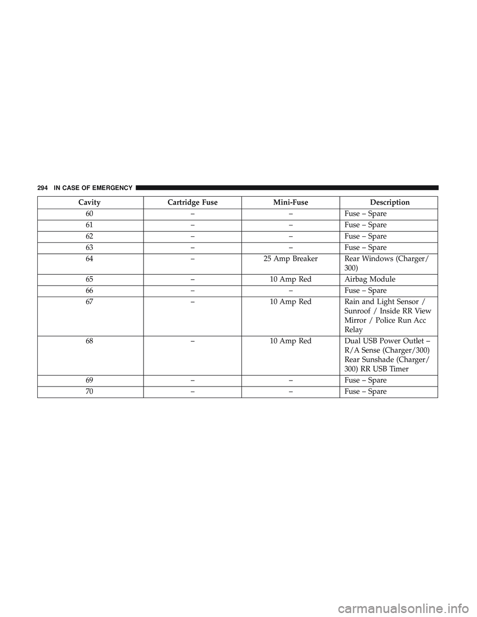
CavityCartridge Fuse Mini-FuseDescription
60 ––Fuse – Spare
61 ––Fuse – Spare
62 ––Fuse – Spare
63 ––Fuse – Spare
64 –25 Amp Breaker Rear Windows (Charger/
300)
65 –10 Amp Red Airbag Module
66 ––Fuse – Spare
67 –10 Amp Red Rain and Light Sensor /
Sunroof / Inside RR View
Mirror / Police Run Acc
Relay
68 –10 Amp Red Dual USB Power Outlet –
R/A Sense (Charger/300)
Rear Sunshade (Charger/
300) RR USB Timer
69 ––Fuse – Spare
70 ––Fuse – Spare
294 IN CASE OF EMERGENCY
Page 297 of 486
TIRE SERVICE KIT — IF EQUIPPED
Small punctures up to 1/4 inch (6 mm) in the tire tread can
be sealed with Tire Service Kit. Foreign objects (e.g., screws
or nails) should not be removed from the tire. Tire Service
Kit can be used in outside temperatures down to approxi-
mately -4°F (-20°C).
This kit will provide a temporary tire seal, allowing you to
drive your vehicle up to 100 miles (160 km) with a
maximum speed of 50 mph (80 km/h).
Tire Service Kit Storage
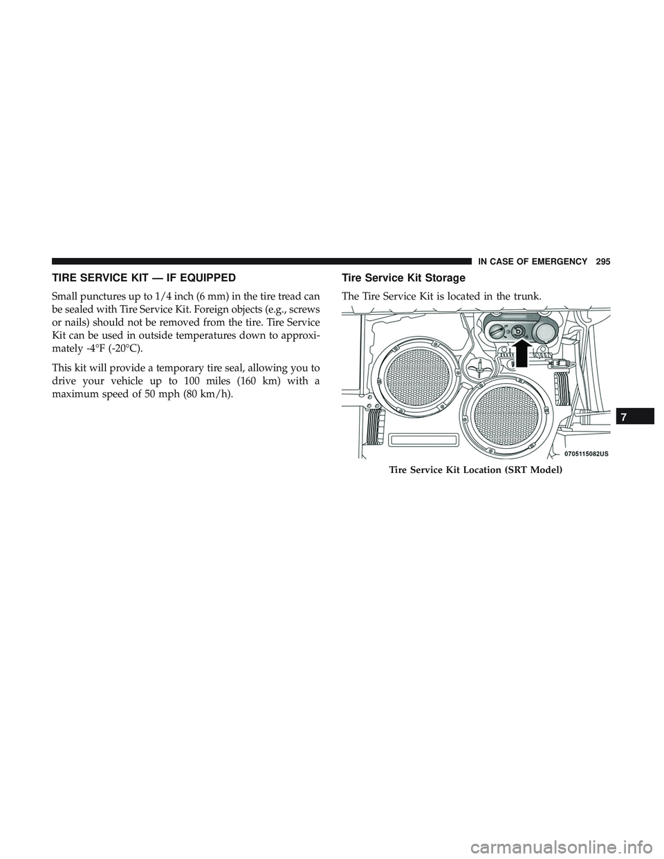
The Tire Service Kit is located in the trunk.
Tire Service Kit Location (SRT Model)
7
IN CASE OF EMERGENCY 295
Page 298 of 486
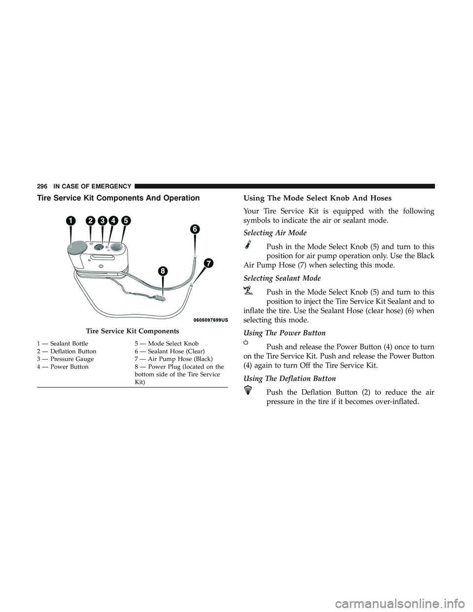
Tire Service Kit Components And OperationUsing The Mode Select Knob And Hoses
Your Tire Service Kit is equipped with the following
symbols to indicate the air or sealant mode.
Selecting Air Mode
Push in the Mode Select Knob (5) and turn to this
position for air pump operation only. Use the Black
Air Pump Hose (7) when selecting this mode.
Selecting Sealant Mode
Push in the Mode Select Knob (5) and turn to this
position to inject the Tire Service Kit Sealant and to
inflate the tire. Use the Sealant Hose (clear hose) (6) when
selecting this mode.
Using The Power Button
Push and release the Power Button (4) once to turn
on the Tire Service Kit. Push and release the Power Button
(4) again to turn Off the Tire Service Kit.
Using The Deflation Button
Push the Deflation Button (2) to reduce the air
pressure in the tire if it becomes over-inflated.
Tire Service Kit Components
1 — Sealant Bottle 5 — Mode Select Knob
2 — Deflation Button 6 — Sealant Hose (Clear)
3 — Pressure Gauge 7 — Air Pump Hose (Black)
4 — Power Button 8 — Power Plug (located on the
bottom side of the Tire Service
Kit)
296 IN CASE OF EMERGENCY
Page 299 of 486
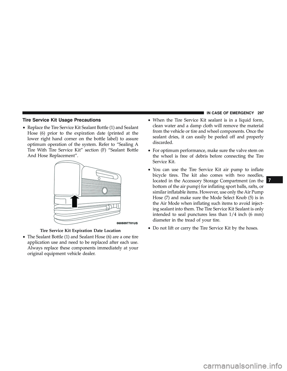
Tire Service Kit Usage Precautions
•Replace the Tire Service Kit Sealant Bottle (1) and Sealant
Hose (6) prior to the expiration date (printed at the
lower right hand corner on the bottle label) to assure
optimum operation of the system. Refer to “Sealing A
Tire With Tire Service Kit” section (F) “Sealant Bottle
And Hose Replacement”.
• The Sealant Bottle (1) and Sealant Hose (6) are a one tire
application use and need to be replaced after each use.
Always replace these components immediately at your
original equipment vehicle dealer. •
When the Tire Service Kit sealant is in a liquid form,
clean water and a damp cloth will remove the material
from the vehicle or tire and wheel components. Once the
sealant dries, it can easily be peeled off and properly
discarded.
• For optimum performance, make sure the valve stem on
the wheel is free of debris before connecting the Tire
Service Kit.
• You can use the Tire Service Kit air pump to inflate
bicycle tires. The kit also comes with two needles,
located in the Accessory Storage Compartment (on the
bottom of the air pump) for inflating sport balls, rafts, or
similar inflatable items. However, use only the Air Pump
Hose (7) and make sure the Mode Select Knob (5) is in
the Air Mode when inflating such items to avoid inject-
ing sealant into them. The Tire Service Kit Sealant is only
intended to seal punctures less than 1/4 inch (6 mm)
diameter in the tread of your tire.
• Do not lift or carry the Tire Service Kit by the hoses.
Tire Service Kit Expiration Date Location
7
IN CASE OF EMERGENCY 297
Page 300 of 486

WARNING!
•Do not attempt to seal a tire on the side of the vehicle
closest to traffic. Pull far enough off the road to avoid
the danger of being hit when using the Tire Service
Kit.
• Do not use Tire Service Kit or drive the vehicle under
the following circumstances:
– If the puncture in the tire tread is approximately 1/4 inch (6 mm) or larger.
– If the tire has any sidewall damage.
– If the tire has any damage from driving with extremely low tire pressure.
– If the tire has any damage from driving on a flat tire.
– If the wheel has any damage.
– If you are unsure of the condition of the tire or the wheel.
• Keep Tire Service Kit away from open flames or heat
source.
• A loose Tire Service Kit thrown forward in a collision
or hard stop could endanger the occupants of the
vehicle. Always stow the Tire Service Kit in the place
provided. Failure to follow these warnings can result
(Continued)
WARNING! (Continued)
in injuries that are serious or fatal to you, your
passengers, and others around you.
• Take care not to allow the contents of Tire Service Kit
to come in contact with hair, eyes, or clothing. Tire
Service Kit sealant is harmful if inhaled, swallowed,
or absorbed through the skin. It causes skin, eye, and
respiratory irritation. Flush immediately with plenty
of water if there is any contact with eyes or skin.
Change clothing as soon as possible, if there is any
contact with clothing.
• Tire Service Kit Sealant solution contains latex. In
case of an allergic reaction or rash, consult a physi-
cian immediately. Keep Tire Service Kit out of reach
of children. If swallowed, rinse mouth immediately
with plenty of water and drink plenty of water. Do
not induce vomiting! Consult a physician immedi-
ately.
Sealing A Tire With Tire Service Kit
(A) Whenever You Stop To Use Tire Service Kit:
1. Pull over to a safe location and turn on the vehicle’s Hazard Warning flashers.
298 IN CASE OF EMERGENCY