ignition DODGE CHARGER 2014 7.G Owner's Manual
[x] Cancel search | Manufacturer: DODGE, Model Year: 2014, Model line: CHARGER, Model: DODGE CHARGER 2014 7.GPages: 148, PDF Size: 3.77 MB
Page 81 of 148
ELECTRONIC CONTROL DAMPING SYSTEM
• This vehicle may be equipped with an electronic controlled damping system. Thissystem reduces body roll and pitch in many driving situations including cornering,
acceleration and braking. There are three modes of operation:
Automatic (Auto) Mode
• This is the default position when vehicleignition is first turned on. This mode will
give a sporty, but comfortable ride. Within
this mode, the suspension will adapt to
the vehicle inputs, including vehicle
speed, steering inputs, braking, and ac-
celeration.
• If AutoStick® is engaged while in “Auto” mode, the transmission will automati-
cally shift up if maximum engine speed is
reached.
• Heavily pressing the accelerator pedal may generate an automatic downshift for improved acceleration.
• This mode should be used for most driving situations.
Sport ModeSPORT
• This mode is driver selectable when the vehicle is placed in SPORT mode (press
the CONTROLS button and then the
SPORT button on the display screen). This
mode will set suspension for maximum
performance handling and is intended for
spirited driving.
• When SPORT mode is enabled, a flag will light up in the instrument cluster.
NOTE:
The SPORT setting will provide a firmer ride.
SRT
79
Page 82 of 148
Track Mode
• In track mode, the transmission has asportier, more aggressive shift pattern.
• This mode includes SPORT Suspension and affects transmission shifting in ei-
ther normal Drive or Autostick®.
• If Autostick® (console shifter or paddle shifters) is engaged while in “Track”
mode, the transmission will remain in the
selected gear even when maximum en-
gine speed is reached. Engine overspeed
protection is achieved through fuel cut off
at or near redline.
• This mode will provide aggressive shifting and is intended for spirited driving.
• The system will return to SPORT mode when the ignition switch is cycled from RUN to OFF, and back to RUN again, if this mode is selected.
SRT PERFORMANCE FEATURES
•The EVIC can be used to view or change the
following SRT Performance Features. Push
the UP
or DOWN buttonuntil SRT
Performance displays in the EVIC, then
push the RIGHT
button. Follow the
prompts to view and set your desired set-
tings. Push the
BACK button to scroll back
to a previous menu or sub menu.
SRT Performance Sub Menu Items
• 0-60 mph (0-100 km/h) • Instantaneous G-Force
• Braking Distance • Peak G-Force
• 1/8 Mile • Digital Speedometer
• 1/4 Mile
0-60 mph (0-100 km/h)
• When selected, this screen displays the time it takes for the vehicle to go from 0 to 60 mph (0 to 100 km/h) within 10 seconds.
SRT
80
Page 86 of 148
ROADSIDE ASSISTANCE
Dial toll-free 1-800-521-2779 for U.S. Residents or 1-800-363-4869 for Canadian Resi-
dents.
• Provide your name, vehicle identification number, license plate number, and your loca-tion, including the telephone number from which you are calling.
• Briefly describe the nature of the problem and answer a few simple questions.
• You will be given the name of the service provider and an estimated time of arrival. If you feel you are in an “unsafe situation”, please let us know. With your consent, we will
contact local police or safety authorities.
INSTRUMENT CLUSTER WARNING LIGHTS
- Electronic Stability Control (ESC) Activation/Malfunction
Indicator Light
The “ESC Activation/Malfunction Indicator Light” in the instrument cluster will come on
when the ignition switch is turned to the ON/RUN position. It should go out with the engine
running. If the “ESC Activation/Malfunction Indicator Light” comes on continuously with
the engine running, a malfunction has been detected in the ESC system.
If this light remains on after several ignition cycles, and the vehicle has been driven several
miles (kilometers) at speeds greater than 30 mph (48 km/h), we recommend you drive to the
nearest service center and have the vehicle serviced immediately.
- Tire Pressure Monitoring System (TPMS) Light
Each tire, including the spare (if provided), should be checked monthly when cold and
inflated to the inflation pressure recommended by the vehicle manufacturer on the vehicle
placard or tire inflation pressure label. (If your vehicle has tires of a different size than the
size indicated on the vehicle placard or tire inflation pressure label, you should determine
the proper tire inflation pressure for those tires.)
As an added safety feature, your vehicle has been equipped with a tire pressure monitoring
system (TPMS) that illuminates a low tire pressure telltale when one or more of your tires is
significantly under-inflated. Accordingly, when the low tire pressure telltale illuminates, you
should stop and check your tires as soon as possible, and inflate them to the proper
pressure. Driving on a significantly under-inflated tire causes the tire to overheat and can
lead to tire failure. Under-inflation also reduces fuel efficiency and tire tread life, and may
affect the vehicle’s handling and stopping ability.
IF THE LIGHT STARTS FLASHING INDICATING A LOW TIRE PRESSURE, ADJUST THE AIR
PRESSURE IN THE LOW TIRE TO THE AIR PRESSURE SHOWN ON THE VEHICLE PLACARD
OR TIRE INFLATION PRESSURE LABEL LOCATED ON THE DRIVER'S DOOR.
WHAT TO DO IN EMERGENCIES
84
Page 89 of 148
- Anti-Lock Brake (ABS) Light
This light monitors the Anti-Lock Brake System (ABS).
If the light is not on during starting, stays on, or turns on while driving, we recommend you
contact the nearest authorized dealer and have the vehicle serviced immediately.
- Electronic Throttle Control (ETC) Indicator Light
This light informs you of a problem with the system.
If a problem is detected, the light will come on while the engine is running. Cycle the ignition
when the vehicle has completely stopped and the shift lever is placed in the PARK position;
the light should turn off.
If the light remains lit with the engine running, your vehicle will usually be drivable; however,
see an authorized dealer immediately. If the light is flashing when the engine is running,
immediate service is required and you may experience reduced performance, an elevated/
rough idle or engine stall and your vehicle may require towing.
- Air Bag Warning Light
If the light is not on during starting, stays on, or turns on while driving, have the vehicle
serviced by an authorized dealer immediately.
SERVICE AWD SYSTEM Message
If the SERVICE AWD SYSTEM warning message appears after engine start up, or during
driving, it means the AWD system is not functioning properly. We recommend you do not
operate the vehicle. Have the vehicle serviced immediately.
– Sport Shifting
This light will illuminate whenSPORT MODEis selected. This mode provides performance
based transmission shifting depending on the driver requested throttle position.
– Sport Suspension Indicator
The light will illuminate when SPORTorTrack MODE is selected. This mode provides
performance based tuning with improved handling through an electronic controlled damp-
ing system.
Oil Change Due
Your vehicle is equipped with an engine oil change indicator system. The “Oil Change Due”
message will flash in the EVIC display for approximately 10 seconds after a single chime
has sounded to indicate the next scheduled oil change interval. The engine oil change
indicator system is duty cycle based, which means the engine oil change interval may
fluctuate dependent upon your personal driving style.
WHAT TO DO IN EMERGENCIES
87
Page 90 of 148
Resetting The Light After Servicing
Vehicles Equipped With Keyless Enter-N-Go™
• Without pressing the brake pedal, push the ENGINE START/STOP button and cycle theignition to the ON/RUN position (do not start the engine.)
• Fully depress the accelerator pedal, slowly, three times within 10 seconds.
• Without pressing the brake pedal, push the ENGINE START/STOP button once to return the ignition to the OFF/LOCK position.
Vehicles Not Equipped With Keyless Enter-N-Go™
• Turn the ignition switch to the ON/RUN position (do not start the engine.)
• Fully depress the accelerator pedal, slowly, three times within 10 seconds.
• Turn the ignition switch to the OFF/LOCK position.
NOTE:
If the indicator message illuminates when you start the vehicle, the oil change indicator
system did not reset. If necessary, repeat this procedure.
IF YOUR ENGINE OVERHEATS
In any of the following situations, you can reduce the potential for overheating by taking the
appropriate action:
• On the highways — slow down.
• In city traffic — while stopped, shift the transmission to NEUTRAL, but do not increase engine idle speed.
NOTE:
There are steps that you can take to slow down an impending overheat condition:
• If your air conditioner (A/C) is on, turn it off. The A/C system adds heat to the engine cooling system and turning the A/C off can help remove this heat.
• You can also turn the temperature control to maximum heat, the mode control to floor and the blower control to high. This allows the heater core to act as a supplement to the
radiator and aids in removing heat from the engine cooling system.
CAUTION!
Driving with a hot cooling system could damage your vehicle. If the temperature gauge
reads HOT (H), pull over and stop the vehicle. Idle the vehicle with the air conditioner
turned off until the pointer drops back into the normal range. If the pointer remains on
HOT (H), and you hear continuous chimes, turn the engine off immediately, and call for
service.
WHAT TO DO IN EMERGENCIES
88
Page 93 of 148
Preparations For Jacking
1. Park the vehicle on a firm, level surface as far from the edge of the roadway as possible.Avoid icy or slippery areas.
2. Turn on the Hazard Warning flasher.
3. Set the parking brake.
4. Place the shift lever into PARK.
5. Turn OFF the ignition.
6. Block the front and rear of the wheel diagonally opposite of the jacking position. For example, if changing the right front tire, block the left rear wheel.
NOTE:
Passengers should not remain in the vehicle
when the vehicle is being jacked.
Jacking And Changing A Tire
1. Remove the spare tire, jack, and lug wrench.
2. If equipped with aluminum wheels where the center cap covers the lug nuts, use
the lug wrench to pry the center cap off
carefully before raising the vehicle.
3. Before raising the vehicle, use the lug wrench to loosen, but not remove, the lug
nuts on the wheel with the flat tire. Turn
the lug nuts counterclockwise one turn
while the wheel is still on the ground.
4. Place the jack underneath the lift area that is closest to the flat tire. Turn the jack screw clockwise to firmly engage the jack saddle with the lift area of the sill flange.
Wheel Blocked
WHAT TO DO IN EMERGENCIES
91
Page 98 of 148
TIREFIT Usage Precautions
• Replace the TIREFIT Sealant Bottle (1) and Sealant Hose (6) prior to the expiration date(printed on the bottle label) to assure optimum operation of the system. Refer to “Sealing
a Tire with TIREFIT” section (F) “Sealant Bottle and Hose Replacement.”
• The Sealant Bottle (1) and Sealant Hose (6) are a one tire application use. After each use, always replace these components immediately at an authorized dealer.
• When the TIREFIT sealant is in a liquid form, clean water, and a damp cloth will remove the material from the vehicle or tire and wheel components. Once the sealant dries, it can
easily be peeled off and properly discarded.
• For optimum performance, make sure the valve stem on the wheel is free of debris before connecting the TIREFIT kit.
• You can use the TIREFIT air pump to inflate bicycle tires. The kit also comes with two needles, located in the Accessory Storage Compartment (on the bottom of the air pump)
for inflating sport balls, rafts, or similar inflatable items. However, use only the Air Pump
Hose (7) and make sure the Mode Select Knob (5) is in the Air Mode when inflating such
items to avoid injecting sealant into them. The TIREFIT Sealant is only intended to seal
punctures less than 1/4” (6 mm) diameter in the tread of your vehicle.
• Do not lift or carry the TIREFIT kit by the hoses.
Sealing A Tire With TIREFIT
(A) Whenever You Stop To Use TIREFIT:
1. Pull over to a safe location and turn on the vehicle’s Hazard Warning flashers.
2. Verify that the valve stem (on the wheel with the deflated tire) is in a position that is near to the ground. This will allow the TIREFIT Hoses (6) and (7) to reach the valve stem and
keep the TIREFIT kit flat on the ground. This will provide the best positioning of the kit
when injecting the sealant into the deflated tire and running the air pump. Move the
vehicle as necessary to place the valve stem in this position before proceeding.
3. Place the transmission in PARK (auto transmission) or in Gear (manual transmission) and cycle the ignition to the OFF position.
4. Set the parking brake.
(B) Setting Up To Use TIREFIT:
1. Turn the Mode Select Knob (5) to the Sealant Mode position.
2. Uncoil the Sealant Hose (6) and then remove the cap from the fitting at the end of the hose.
3. Place the TIREFIT kit flat on the ground next to the deflated tire.
4. Remove the cap from the valve stem and then screw the fitting at the end of the Sealant Hose (6) onto the valve stem.
5. Uncoil the Power Plug (8) and insert the plug into the vehicle’s 12 Volt power outlet.
6. Do not remove foreign objects (e.g., screws or nails) from the tire.
WHAT TO DO IN EMERGENCIES
96
Page 103 of 148
BATTERY LOCATION
The battery is stored under an access cover in the trunk. Remote battery posts are located
on the right side of the engine compartment for jump-starting.
JUMP-STARTING
If your vehicle has a discharged battery it can be jump-started using a set of jumper cables
and a battery in another vehicle or by using a portable battery booster pack.
Jump-starting can be dangerous if done improperly so please follow the procedures in this
section carefully.
NOTE:
When using a portable battery booster pack
follow the manufacturer’s operating instruc-
tions and precautions.
Preparations For Jump-Start
The battery is stored under an access cover
in the trunk. Remote battery posts are lo-
cated on the right side of the engine com-
partment for jump-starting.
NOTE:
The remote battery posts are viewed by
standing on the right side of the vehicle
looking over the fender.
• Set the parking brake, shift the automatic transmission into PARK and turn the ignition toOFF.
• Turn off the heater, radio, and all unnecessary electrical accessories.
• If using another vehicle to jump-start the battery, park the vehicle within the jumper cables reach, set the parking brake and make sure the ignition is OFF.
WHAT TO DO IN EMERGENCIES
101
Page 105 of 148
WARNING!
• When temperatures are below the freezing point, electrolyte in a discharged batterymay freeze. Do not attempt jump-starting because the battery could rupture or
explode and cause personal injury. Battery temperature must be brought above
freezing point before attempting a jump-start.
• Take care to avoid the radiator cooling fan whenever the hood is raised. It can start anytime the ignition switch is on. You can be injured by moving fan blades.
• Remove any metal jewelry, such as watch bands or bracelets, that might make an
inadvertent electrical contact. You could be severely injured.
•
Batteries contain sulfuric acid that can burn your skin or eyes and generate hydrogen gas
which is flammable and explosive. Keep open flames or sparks away from the battery.
• Do not allow vehicles to touch each other as this could establish a ground connection
and personal injury could result.
• Failure to follow this procedure could result in personal injury or property damage due to battery explosion.
• Do not connect the cable to the negative post (-)of the discharged battery. The
resulting electrical spark could cause the battery to explode and could result in
personal injury.
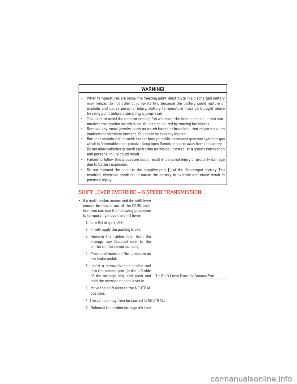
SHIFT LEVER OVERRIDE — 5 SPEED TRANSMISSION
• If a malfunction occurs and the shift lever cannot be moved out of the PARK posi-
tion, you can use the following procedure
to temporarily move the shift lever:
1. Turn the engine OFF.
2. Firmly apply the parking brake.
3. Remove the rubber liner from the storage tray (located next to the
shifter on the center console).
4. Press and maintain firm pressure on the brake pedal.
5. Insert a screwdriver or similar tool into the access port (in the left side
of the storage bin), and push and
hold the override release lever in.
6. Move the shift lever to the NEUTRAL position.
7. The vehicle may then be started in NEUTRAL.
8. Reinstall the rubber storage bin liner.
1 — Shift Lever Override Access Port
WHAT TO DO IN EMERGENCIES
103
Page 108 of 148
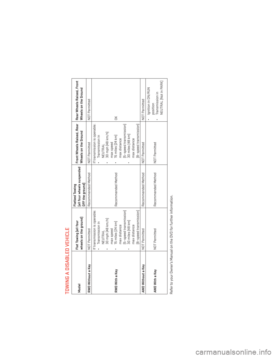
TOWING A DISABLED VEHICLEModelFlat Towing (all four
wheels on the ground) Flatbed Towing
(all four wheels suspended
OFF the ground)Front Wheels Raised, Rear
Wheels on the Ground
Rear Wheels Raised, Front
Wheels on the Ground
RWDWithoutaKey NOT Permitted Recommended Method NOT Permitted NOT Permitted
RWDWithaKey If transmission is operable:
• Transmission in
NEUTRAL
• 30 mph (48 km/h)
max speed
• 15 miles (24 km)
max distance
(5–speed transmission)
• 30 miles (48 km)
max distance
(8–speed transmission) Recommended Method If transmission is operable:
• Transmission in
NEUTRAL
• 30 mph (48 km/h)
max speed
• 15 miles (24 km)
max distance
(5–speed transmission)
• 30 miles (48 km)
max distance
(8–speed transmission) OK
AWDWithoutaKey NOT Permitted
Recommended Method NOT Permitted NOT Permitted
AWDWithaKey NOT Permitted
Recommended Method NOT Permitted • Ignition in ON/RUN
position
• Transmission in
NEUTRAL (Not in PARK)Refer to your Owner’s Manual on the DVD for further information.
WHAT TO DO IN EMERGENCIES
106