run flat DODGE CHARGER 2015 7.G User Guide
[x] Cancel search | Manufacturer: DODGE, Model Year: 2015, Model line: CHARGER, Model: DODGE CHARGER 2015 7.GPages: 236, PDF Size: 35.67 MB
Page 23 of 236
•TheORCturnsontheAirBagWarningLightintheinstrumentpanelforapproximately
four to eight seconds for a self-check when the ignition switch is first turned to the
ON/RUN position. After the self-check, the Air Bag Warning Light will turn off. If the
ORC detects a malfunction in any part of the system, it turns on the Air Bag Warning
Light, either momentarily or continuously. A single chime will sound to alert you if the
light comes on again after initial startup.
•The ORC monitors the readiness of the electronic parts of the air bag system whenever the
ignition switch is in the START or ON/RUN position. If the ignition switch is in the OFF
position or in the ACC position, the air bag system is not on and the air bags will not inflate.
•If the Air Bag Warning Light in the instrument panel is not on during the four to eight
seconds when the ignition switch is first turned to the ON/RUN position, stays on, or turns
on while driving, have the vehicle serviced by an authorized service center immediately.
NOTE:
If the speedometer, tachometer, or any engine related gauges are not working, the
Occupant Restraint Controller (ORC) may also be disabled. In this condition the air bags
may not be ready to inflate for your protection. Have an authorized dealer service the air
bag system immediately.
•Afteranycollision,thevehicleshouldbetakentoanauthorizeddealerimmediately.
•Donotdriveyourvehicleaftertheairbagshavedeployed.Ifyouareinvolvedinanother
collision, the air bags will not be in place to protect you.
•Ifitisnecessarytomodifytheairbagsystemforpersonswithdisabilities,contactyour
authorized dealer.
•RefertotheOwner'sManualontheDVDregardingtheSupplementalRestraintSystem
(SRS) for further information.
Supplemental Knee Air Bags
This vehicle is equipped with a Supplemental Driver Knee Air Bag mounted in the
instrument panel below the steering column. The Supplemental Driver Knee Air Bag
provides enhanced protection during a frontal impact by working together with the seat
belts, pretensioners, and Advanced Front Air Bags.
WARNING!
•Relyingontheairbagsalonecouldleadtomoresevereinjuriesinacollision.The
air bags work with your seat belt to restrain you properly. In some collisions, the air
bags won't deploy at all. Always wear your seat belts even though you have air bags.
•BeingtooclosetothesteeringwheelorinstrumentpanelduringAdvancedFrontAir
Bag deployment could cause serious injury, including death. Air bags need room to
inflate. Sit back, comfortably extending your arms to reach the steering wheel or
instrument panel.
•Noobjectsshouldbeplacedoverorneartheairbagontheinstrumentpanelor
steering wheel because any such objects could cause harm if the vehicle is in a
collision severe enough to cause the air bag to inflate.
GETTING STARTED
21
Page 162 of 236
Electronic Throttle Control (ETC) Indicator Light
This light informs you of a problem with the system.
If a problem is detected, the light will come on while the engine is running. Cycle the
ignition when the vehicle has completely stopped and the shift lever is placed in the PARK
position; the light should turn off.
If the light remains lit with the engine running, your vehicle will usually be drivable.
However, see an authorized dealer immediately. If the light is flashing when the engine is
running, immediate service is required, and you may experience reduced performance, an
elevated/rough idle or engine stall, and your vehicle may require towing.
Tire Pressure Monitoring System (TPMS) Light
Each tire, including the spare (if provided), should be checked monthly when cold and
inflated to the inflation pressure recommended by the vehicle manufacturer on the
vehicle placard or tire inflation pressure label. (If your vehicle has tires of a different size
than the size indicated on the vehicle placard or tire inflation pressure label, you should
determine the proper tire inflation pressure for those tires).
As an added safety feature, your vehicle has been equipped with a tire pressure
monitoring system (TPMS) that illuminates a low tire pressure telltale when one or more
of your tires is significantly under-inflated. Accordingly, when the low tire pressure telltale
illuminates, you should stop and check your tires as soon as possible and inflate them to
the proper pressure. Driving on a significantly under-inflated tire causes the tire to
overheat and can lead to tire failure. Under-inflation also reduces fuel efficiency and tire
tread life and may affect the vehicle’s handling and stopping ability.
IF THE LIGHT STARTS FLASHING INDICATING A LOW TIRE PRESSURE, ADJUST THE AIR
PRESSURE IN THE LOW TIRE TO THE AIR PRESSURE SHOWN ON THE VEHICLE PLACARD OR
TIRE INFLATION PRESSURE LABEL LOCATED ON THE DRIVER'S DOOR.
NOTE:
AFTER INFLATION, THE VEHICLE MAY NEED TO BE DRIVEN FOR 20 MINUTES
BEFORE THE FLASHING LIGHT WILL TURN OFF.
Please note that the TPMS is not a substitute for proper tire maintenance, and it is the
driver’s responsibility to maintain correct tire pressure, even if under-inflation has not
reached the level to trigger illumination of the TPMS low tire pressure telltale.
Yo u r v e h i c l e h a s a l s o b e e n e q u i p p e d w i t h a T P M S m a l f u n c t i o n i n d i c a t o r t o i n d i c a t e w h e n
the system is not operating properly. The TPMS malfunction indicator is combined with
the low tire pressure telltale.
WHAT TO DO IN EMERGENCIES
160
Page 173 of 236
CAUTION!
Do not attempt to raise the vehicle by jacking on locations other than those indicatedin the Jacking Instructions for this vehicle.
WARNING!
•Do not attempt to change a tire on the side of the vehicle close to moving traffic. Pullfar enough off the road to avoid the danger of being hit when operating the jack orchanging the wheel.
•Beingunderajacked-upvehicleisdangerous.Thevehiclecouldslipoffthejackand fall on you. You could be crushed. Never put any part of your body under avehicle that is on a jack.
•Neverstartorruntheenginewhilethevehicleisonajack.Ifyouneedtogetunder
araisedvehicle,takeittoaservicecenterwhereitcanberaisedonalift.
•Thejackisdesignedtobeusedasatoolforchangingtiresonly.Thejackshouldnot
be used to lift the vehicle for service purposes. The vehicle should be jacked on a
firm level surface only. Avoid ice or slippery areas.
•Aloosetireorjackthrownforwardinacollisionorhardstopcouldendangerthe
occupants of the vehicle. Always stow the jack parts and the spare tire in the places
provided.
•Carefullyfollowthesetirechangingwarningstohelppreventpersonalinjuryor
damage to your vehicle:
•Alwaysparkonafirm,levelsurfaceasfarfromtheedgeoftheroadwayaspossible
before raising the vehicle.
•TurnontheHazardWarningflasher.
•Blockthewheeldiagonallyoppositethewheeltoberaised.
•SettheparkingbrakefirmlyandsetanautomatictransmissioninPARK;amanual
transmission in REVERSE.
•Donotletanyonesitinthevehiclewhenitisonajack.
•Donotgetunderthevehiclewhenitisonajack.
•Onlyusethejackinthepositionsindicatedandforliftingthisvehicleduringatire
change.
•Ifworkingonorneararoadway,beextremelycarefulofmotortraffic.
•Raising the vehicle higher than necessary can make the vehicle less stable. It could slip
off the jack and hurt someone near it. Raise the vehicle only enough to remove the tire.
•Toavoidtheriskofforcingthevehicleoffthejack,donotfullytightenthewheel
nuts until the vehicle has been lowered. Failure to follow this warning may result in
personal injury.
•Aloosetireorjackthrownforwardinacollisionorhardstopcouldendangertheoccu-
pantsof the vehicle. Always stow the jack parts and the spare tire in the places provided.
•Thelimited-usesparetiresareforemergencyuseonly.Installationofthislimited-use spare tire affects vehicle handling. With this tire, do not drive more than60 mph (100 km/h). Keep inflated to the cold tire inflation pressure listed on eitheryour tire placard or limited-use spare tire and wheel assembly. Replace (or repair)the original tire at the first opportunity and reinstall it on your vehicle. Failure to doso could result in loss of vehicle control.
WHAT TO DO IN EMERGENCIES
171
Page 174 of 236
TIRE SERVICE KIT
Yo u r v e h i c l e m a y b e e q u i p p e d w i t h a Ti r e S e r v i c e K i t .
Small punctures up to 1/4” (6 mm) in the tire tread can be sealed with the Tire Service Kit.
Foreign objects (e.g., screws or nails) should not be removed from the tire. The Tire Service
Kit can be used in outside temperatures down to approximately -4°F (-20°C).
This kit will provide a temporary tire seal, allowing you to drive your vehicle up to
100 miles (160 km) with a maximum speed of 55 mph (90 km/h).
Tire Service Kit Storage
The Tire Service Kit is located in the trunk.
Tire Service Kit Components And Operation
Using The Mode Select Knob And Hoses
Yo u r Ti r e S e r v i c e K i t i s e q u i p p e d w i t h t h e
following symbols to indicate the air or seal-
ant mode.
Selecting Air Mode
Tu r n t h e M o d e S e l e c t K n o b ( 5 ) t o t h i s p o s i -
tion for air pump operation only. Use the
Black Air Pump Hose (7) when selecting
this mode.
Selecting Sealant Mode
Tu r n t h e M o d e S e l e c t K n o b ( 5 ) t o t h i s p o s i -
tion to inject the Tire Service Kit Sealant
and to inflate the tire. Use the Sealant Hose
(clear hose) (6) when selecting this mode.
Using The Power Button
Push and release the Power Button (4) once
to turn On the Tire Service Kit. Push and
release the Power Button (4) again to turn
Off the Tire Service Kit.
Using The Deflation Button
Push the Deflation Button (2) to reduce the
air pressure in the tire if it becomes over-
inflated.
Tire Service Kit Components
1—SealantBottle2—DeflationButton3—PressureGauge4—PowerButton5—ModeSelectKnob6—SealantHose(Clear)7—AirPumpHose(Black)8—PowerPlug(locatedonbottomsideof Tire Service Kit)
WHAT TO DO IN EMERGENCIES
172
Page 175 of 236
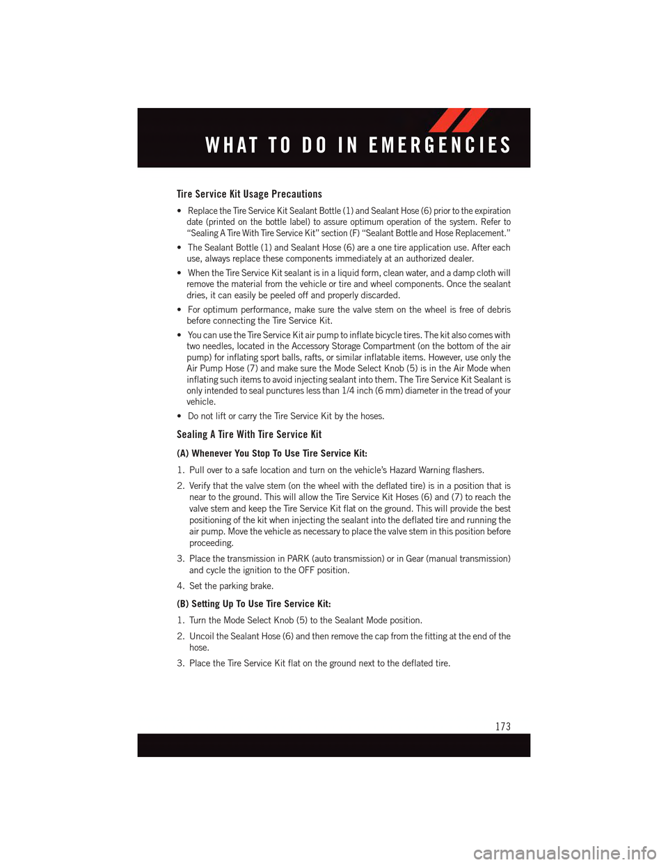
Tire Service Kit Usage Precautions
•Replace the Tire Service Kit Sealant Bottle (1) and Sealant Hose (6) prior to the expiration
date (printed on the bottle label) to assure optimum operation of the system. Refer to
“Sealing A Tire With Tire Service Kit” section (F) “Sealant Bottle and Hose Replacement.”
•TheSealantBottle(1)andSealantHose(6)areaonetireapplicationuse.Aftereach
use, always replace these components immediately at an authorized dealer.
•WhentheTireServiceKitsealantisinaliquidform,cleanwater,andadampclothwill
remove the material from the vehicle or tire and wheel components. Once the sealant
dries, it can easily be peeled off and properly discarded.
•Foroptimumperformance,makesurethevalvestemonthewheelisfreeofdebris
before connecting the Tire Service Kit.
•YoucanusetheTireServiceKitairpumptoinflatebicycletires.Thekitalsocomeswith
two needles, located in the Accessory Storage Compartment (on the bottom of the air
pump) for inflating sport balls, rafts, or similar inflatable items. However, use only the
Air Pump Hose (7) and make sure the Mode Select Knob (5) is in the Air Mode when
inflating such items to avoid injecting sealant into them. The Tire Service Kit Sealant is
only intended to seal punctures less than 1/4 inch (6 mm) diameter in the tread of your
vehicle.
•DonotliftorcarrytheTireServiceKitbythehoses.
Sealing A Tire With Tire Service Kit
(A) Whenever You Stop To Use Tire Service Kit:
1. Pull over to a safe location and turn on the vehicle’s Hazard Warning flashers.
2. Verify that the valve stem (on the wheel with the deflated tire) is in a position that is
near to the ground. This will allow the Tire Service Kit Hoses (6) and (7) to reach the
valve stem and keep the Tire Service Kit flat on the ground. This will provide the best
positioning of the kit when injecting the sealant into the deflated tire and running the
air pump. Move the vehicle as necessary to place the valve stem in this position before
proceeding.
3. Place the transmission in PARK (auto transmission) or in Gear (manual transmission)
and cycle the ignition to the OFF position.
4. Set the parking brake.
(B) Setting Up To Use Tire Service Kit:
1. Turn the Mode Select Knob (5) to the Sealant Mode position.
2. Uncoil the Sealant Hose (6) and then remove the cap from the fitting at the end of the
hose.
3. Place the Tire Service Kit flat on the ground next to the deflated tire.
WHAT TO DO IN EMERGENCIES
173
Page 176 of 236
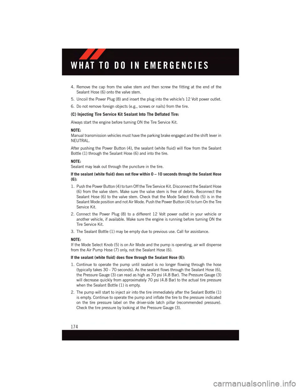
4. Remove the cap from the valve stem and then screw the fitting at the end of the
Sealant Hose (6) onto the valve stem.
5. Uncoil the Power Plug (8) and insert the plug into the vehicle’s 12 Volt power outlet.
6. Do not remove foreign objects (e.g., screws or nails) from the tire.
(C) Injecting Tire Service Kit Sealant Into The Deflated Tire:
Always start the engine before turning ON the Tire Service Kit.
NOTE:
Manual transmission vehicles must have the parking brake engaged and the shift lever in
NEUTRAL.
After pushing the Power Button (4), the sealant (white fluid) will flow from the Sealant
Bottle (1) through the Sealant Hose (6) and into the tire.
NOTE:
Sealant may leak out through the puncture in the tire.
If the sealant (white fluid) does not flow within 0 – 10seconds through the Sealant Hose
(6):
1. Push the Power Button (4) to turn Off the Tire Service Kit. Disconnect the Sealant Hose
(6) from the valve stem. Make sure the valve stem is free of debris. Reconnect the
Sealant Hose (6) to the valve stem. Check that the Mode Select Knob (5) is in the
Sealant Mode position and not Air Mode. Push the Power Button (4) to turn On the Tire
Service Kit.
2. Connect the Power Plug (8) to a different 12 Volt power outlet in your vehicle or
another vehicle, if available. Make sure the engine is running before turning ON the
Ti r e S e r v i c e K i t .
3. The Sealant Bottle (1) may be empty due to previous use. Call for assistance.
NOTE:
If the Mode Select Knob (5) is on Air Mode and the pump is operating, air will dispense
from the Air Pump Hose (7) only, not the Sealant Hose (6).
If the sealant (white fluid) does flow through the Sealant Hose (6):
1. Continue to operate the pump until sealant is no longer flowing through the hose
(typically takes 30 - 70 seconds). As the sealant flows through the Sealant Hose (6),
the Pressure Gauge (3) can read as high as 70 psi (4.8 Bar). The Pressure Gauge (3)
will decrease quickly from approximately 70 psi (4.8 Bar) to the actual tire pressure
when the Sealant Bottle (1) is empty.
2. The pump will start to inject air into the tire immediately after the Sealant Bottle (1)
is empty. Continue to operate the pump and inflate the tire to the pressure indicated
on the tire pressure label on the driver-side latch pillar (recommended pressure).
Check the tire pressure by looking at the Pressure Gauge (3).
WHAT TO DO IN EMERGENCIES
174
Page 184 of 236
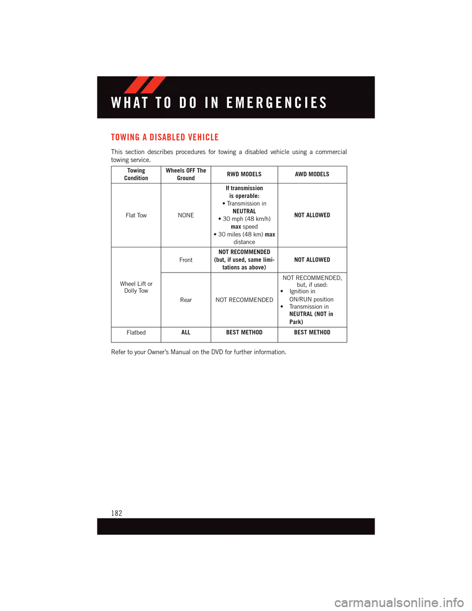
TOWING A DISABLED VEHICLE
This section describes procedures for towing a disabled vehicle using a commercial
towing service.
TowingConditionWheels OFF TheGroundRWD MODELSAWD MODELS
Flat TowNONE
If transmissionis operable:•TransmissioninNEUTRAL•30mph(48km/h)maxspeed•30miles(48km)maxdistance
NOT ALLOWED
Wheel Lift orDolly Tow
Front
NOT RECOMMENDED(but, if used, same limi-tations as above)NOT ALLOWED
Rear NOT RECOMMENDED
NOT RECOMMENDED,but, if used:•Ignitionin
ON/RUN position•TransmissioninNEUTRAL (NOT in
Park)
FlatbedALLBEST METHODBEST METHOD
Refer to your Owner’s Manual on the DVD for further information.
WHAT TO DO IN EMERGENCIES
182
Page 225 of 236
Oil Pressure Warning Light . . . .159Ti r e P r e s s u r e M o n i t o r i n g S y s t e m(TPMS) Light...........160Tu r n S i g n a l I n d i c a t o r.......163Vehicle Security Light.......163Clutch . . . . . . . . . . . . . . . . .198Clutch Fluid . . . . . . . . . . . . . .198Compact Spare Tire..........214Compass Calibration..........143Cooling System.............198Adding Coolant (Antifreeze)....198Coolant Capacity.........194Coolant Level...........198Disposal Of Used Coolant.....198Drain, Flush, And Refill......198Inspection . . . . . . . . . . . . .198Points To Remember.......198Pressure Cap . . . . . . . . . . .198Selection Of Coolant(Antifreeze) . . .194, 195, 196, 198Corrosion Protection..........198Cruise Control (Speed Control).....43Cruise Light . . . . . . . . . . . . . . .43Customer Assistance..........218Customer Programmable Features . .147
Deck Lid, Emergency Release.....18Deck Lid, Power Release........17Defects, Reporting...........219Defroster, Rear Window.........56Defroster, Windshield . . . . . . . . . .56Dimmer Control.............42Dimmer Switch, Headlight.......42Disabled Vehicle Towing . . . . .159, 182Disarming, Security System.......19DisposalAntifreeze (Engine Coolant)....198Door Locks................12Drive Modes...........147, 155
E-85 Fuel................195Electronic Power Distribution Center(Fuses) . . . . . . . . . . . . . . .208ElectronicsYo u r Ve h i c l e ' s S o u n d S y s t e m....62Electronic Speed Control (CruiseControl) . . . . . . . . . . . . . . . .43
Electronic Stability Control (ESC) . . .162Electronic Stability Control (ESC)OFF Indicator . . . . . . . . .163, 164Electronic Throttle Control WarningLight . . . . . . . . . . . . . . . . .160Electronic Vehicle Information Center(EVIC) . . . . . . . . . . . . . . . .142Emergency Deck Lid Release......18Emergency, In Case OfJacking..............166Overheating............165To w i n g . . . . . . . . . . . .159, 182Emergency Key.............12Emergency Trunk Release........18EngineAir Cleaner . . . . . . . . . . . . .198Break-In Recommendations..38,39Checking Oil Level.........198Compartment............186Coolant (Antifreeze).....195, 196Cooling . . . . . . . . . . . . . . .198Oil . . . . . . . .194, 195, 196, 198Oil Change Interval........164Oil Filler Cap...........198Oil Selection . . . . . . . . .194, 198Overheating............165Starting...............16Stopping..............16Te m p e r a t u r e W a r n i n g L i g h t....161Ethanol.................195Event Data Recorder..........184Exhaust System............198
FA Q . . . . . . . . . . . . . . . . . . . 2 2 1FiltersAir Cleaner . . . . . . . . . . . . .198Engine Oil.......195, 196, 198Engine Oil Disposal........198FlashersTu r n S i g n a l............163Flat Tire Changing...........166Flexible Fuel Vehicles.........195Fluid, Brake . . . . . . . . . . .196, 197Fluid Capacities............194Fluids, Lubricants AndGenuine Parts.........195, 196Fog Lights . . . . . . . . . . . . .42, 163
INDEX
223