length DODGE CHARGER 2021 Owners Manual
[x] Cancel search | Manufacturer: DODGE, Model Year: 2021, Model line: CHARGER, Model: DODGE CHARGER 2021Pages: 320, PDF Size: 20.61 MB
Page 27 of 320

GETTING TO KNOW YOUR VEHICLE25
STEERING WHEEL
MANUAL TILT/TELESCOPING STEERING
C
OLUMN — IF EQUIPPED
This feature allows you to tilt the steering column
upward or downward. It also allows you to lengthen
or shorten the steering column. The tilt/telescoping
control is located below the steering wheel at the
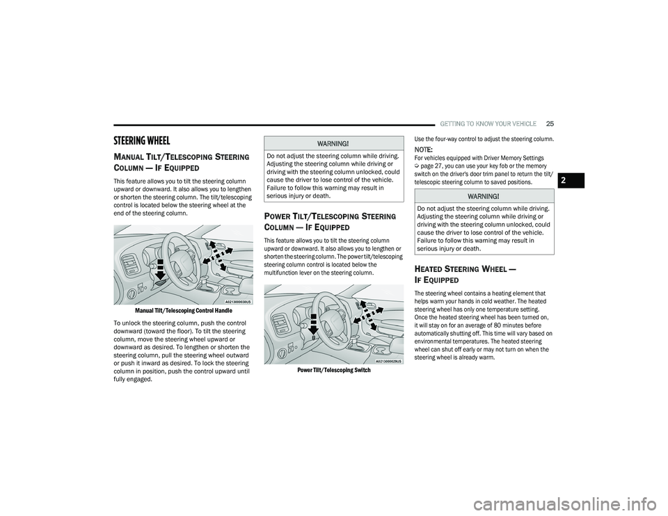
end of the steering column.
Manual Tilt/Telescoping Control Handle
To unlock the steering column, push the control
downward (toward the floor). To tilt the steering
column, move the steering wheel upward or
downward as desired. To lengthen or shorten the
steering column, pull the steering wheel outward
or push it inward as desired. To lock the steering
column in position, push the control upward until
fully engaged.
POWER TILT/TELESCOPING STEERING
C
OLUMN — IF EQUIPPED
This feature allows you to tilt the steering column
upward or downward. It also allows you to lengthen or
shorten the steering column. The power tilt/telescoping
steering column control is located below the
multifunction lever on the steering column.
Power Tilt/Telescoping Switch
Use the four-way control to adjust the steering column.
NOTE:
For vehicles equipped with Driver Memory Settings
Ú
page 27, you can use your key fob or the memory
switch on the driver's door trim panel to return the tilt/
telescopic steering column to saved positions.
HEATED STEERING WHEEL —
I
F EQUIPPED
The steering wheel contains a heating element that
helps warm your hands in cold weather. The heated
steering wheel has only one temperature setting.
Once the heated steering wheel has been turned on,
it will stay on for an average of 80 minutes before
automatically shutting off. This time will vary based on
environmental temperatures. The heated steering
wheel can shut off early or may not turn on when the
steering wheel is already warm.
WARNING!
Do not adjust the steering column while driving.
Adjusting the steering column while driving or
driving with the steering column unlocked, could
cause the driver to lose control of the vehicle.
Failure to follow this warning may result in
serious injury or death.
WARNING!
Do not adjust the steering column while driving.
Adjusting the steering column while driving or
driving with the steering column unlocked, could
cause the driver to lose control of the vehicle.
Failure to follow this warning may result in
serious injury or death.
2
21_LD_OM_EN_USC_t.book Page 25
Page 60 of 320

58GETTING TO KNOW YOUR VEHICLE
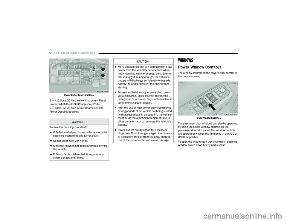
Power Outlet Fuse Locations
WINDOWS
POWER WINDOW CONTROLS
The window controls on the driver's door control all
the door windows.
Power Window Switches
The passenger door windows can also be operated
by using the single window controls on the
passenger door trim panel. The window controls
will operate only when the ignition is in the ACC or
ON/RUN position.
To open the window part way (manually), push the
window switch down briefly and release.
1 — #12 Fuse 20 Amp Yellow Instrument Panel
Power Outlet/Dual USB Charge Only Ports
2 — #38 Fuse 20 Amp Yellow Center Console
Power Outlet/Media Hub
WARNING!
To avoid serious injury or death:
Only devices designed for use in this type of outlet
should be inserted into any 12 Volt outlet.
Do not touch with wet hands.
Close the lid when not in use and while driving
the vehicle.
If this outlet is mishandled, it may cause an
electric shock and failure.
CAUTION!
Many accessories that can be plugged in draw
power from the vehicle's battery even when
not in use (i.e., cellular phones, etc.). Eventu
-
ally, if plugged in long enough, the vehicle's
battery will discharge sufficiently to degrade
battery life and/or prevent the engine from
starting.
Accessories that draw higher power (i.e., coolers,
vacuum cleaners, lights, etc.) will degrade the
battery even more quickly. Only use these intermit -
tently and with greater caution.
After the use of high power draw accessories
or long periods of the vehicle not being started
(with accessories still plugged in), the vehicle
must be driven a sufficient length of time to
allow the alternator to recharge the vehicle's
battery.
Power outlets are designed for accessory
plugs only. Do not hang any type of accessory
or accessory bracket from the plug. Improper
use of the power outlet can cause damage.
21_LD_OM_EN_USC_t.book Page 58
Page 130 of 320

128MULTIMEDIA
Voice
Clock
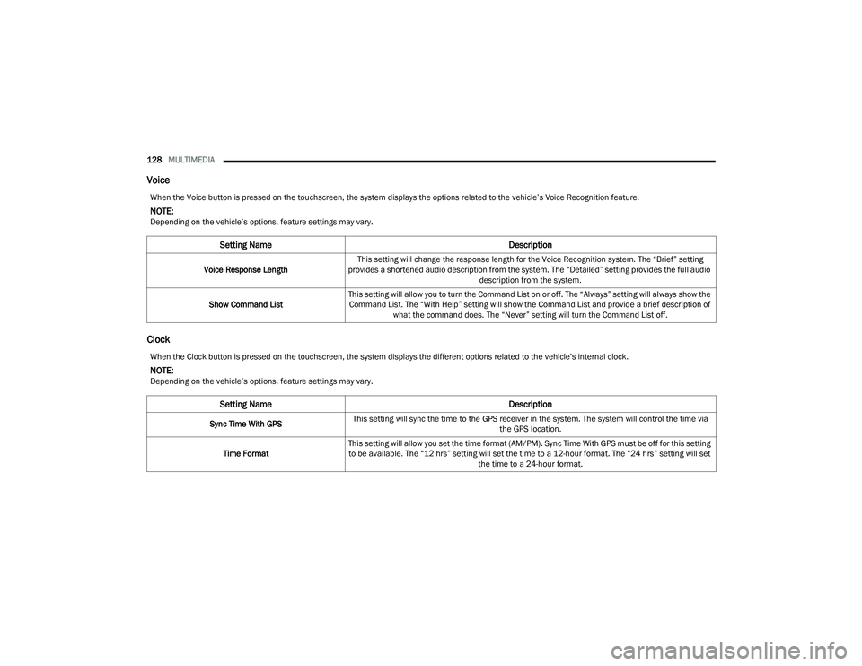
When the Voice button is pressed on the touchscreen, the system displays the options related to the vehicle’s Voice Recognition feature.
NOTE:Depending on the vehicle’s options, feature settings may vary.
Setting Name Description
Voice Response LengthThis setting will change the response length for the Voice Recognition system. The “Brief” setting
provides a shortened audio description from the system. The “Detailed” setting provides the full audio description from the system.
Show Command List This setting will allow you to turn the Command List on or off. The “Always” setting will always show the
Command List. The “With Help” setting will show the Command List and provide a brief description of what the command does. The “Never” setting will turn the Command List off.
When the Clock button is pressed on the touchscreen, the system displays the different options related to the vehicle’s internal clock.
NOTE:Depending on the vehicle’s options, feature settings may vary.
Setting Name Description
Sync Time With GPSThis setting will sync the time to the GPS receiver in the system. The system will control the time via
the GPS location.
Time Format This setting will allow you set the time format (AM/PM). Sync Time With GPS must be off for this setting
to be available. The “12 hrs” setting will set the time to a 12-hour format. The “24 hrs” setting will set the time to a 24-hour format.
21_LD_OM_EN_USC_t.book Page 128
Page 187 of 320

SAFETY185
Rain Brake Support (RBS)
RBS may improve braking performance in wet
conditions. It will periodically apply a small amount
of brake pressure to remove any water buildup
on the front brake rotors. It functions when the
windshield wipers are in LO or HI speed. When RBS
is active, there is no notification to the driver and
no driver interaction is required.
Ready Alert Braking (RAB)
RAB may reduce the time required to reach full braking
during emergency braking situations. It anticipates
when an emergency braking situation may occur by
monitoring how fast the throttle is released by the
driver. The Electronic Brake Controller (EBC) will
prepare the brake system for a panic stop.
Traction Control System (TCS)
The TCS monitors the amount of wheel spin of each of
the driven wheels. If wheel spin is detected, the TCS
may apply brake pressure to the spinning wheel(s)
and/or reduce engine power to provide enhanced
acceleration and stability. A feature of the TCS, Brake
Limited Differential (BLD) functions similarly to a
limited slip differential and controls the wheel spin
across a driven axle. If one wheel on a driven axle is
spinning faster than the other, the system will apply the
brake of the spinning wheel. This will allow more engine
power to be applied to the wheel that is not spinning.
BLD may remain enabled even if TCS and ESC are in
reduced modes.
AUXILIARY DRIVING SYSTEMS
BLIND SPOT MONITORING (BS M) —
I
F EQUIPPED
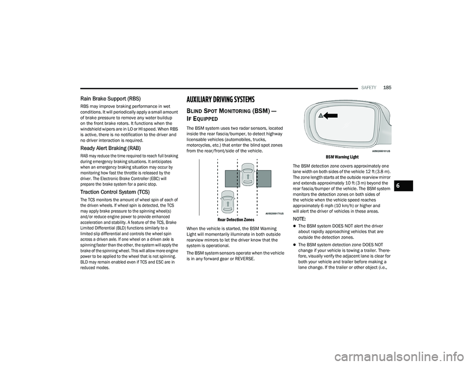
The BSM system uses two radar sensors, located
inside the rear fascia/bumper, to detect highway
licensable vehicles (automobiles, trucks,
motorcycles, etc.) that enter the blind spot zones
from the rear/front/side of the vehicle.
Rear Detection Zones
When the vehicle is started, the BSM Warning
Light will momentarily illuminate in both outside
rearview mirrors to let the driver know that the
system is operational.
The BSM system sensors operate when the vehicle
is in any forward gear or REVERSE.
BSM Warning Light
The BSM detection zone covers approximately one
lane width on both sides of the vehicle 12 ft (3.8 m).
The zone length starts at the outside rearview mirror
and extends approximately 10 ft (3 m) beyond the
rear fascia/bumper of the vehicle. The BSM system
monitors the detection zones on both sides of
the vehicle when the vehicle speed reaches
approximately 6 mph (10 km/h) or higher and
will alert the driver of vehicles in these areas.
NOTE:
The BSM system DOES NOT alert the driver
about rapidly approaching vehicles that are
outside the detection zones.
The BSM system detection zone DOES NOT
change if your vehicle is towing a trailer. There -
fore, visually verify the adjacent lane is clear for
both your vehicle and trailer before making a
lane change. If the trailer or other object (i.e.,
6
21_LD_OM_EN_USC_t.book Page 185