instrument cluster DODGE CHARGER SRT 2015 7.G User Guide
[x] Cancel search | Manufacturer: DODGE, Model Year: 2015, Model line: CHARGER SRT, Model: DODGE CHARGER SRT 2015 7.GPages: 595, PDF Size: 16.43 MB
Page 251 of 595
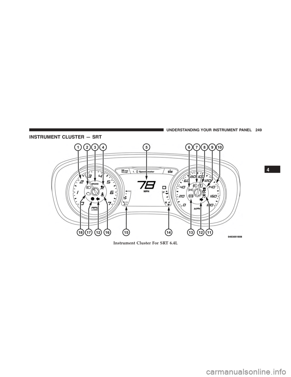
INSTRUMENT CLUSTER — SRT
Instrument Cluster For SRT 6.4L
4
UNDERSTANDING YOUR INSTRUMENT PANEL 249
Page 252 of 595
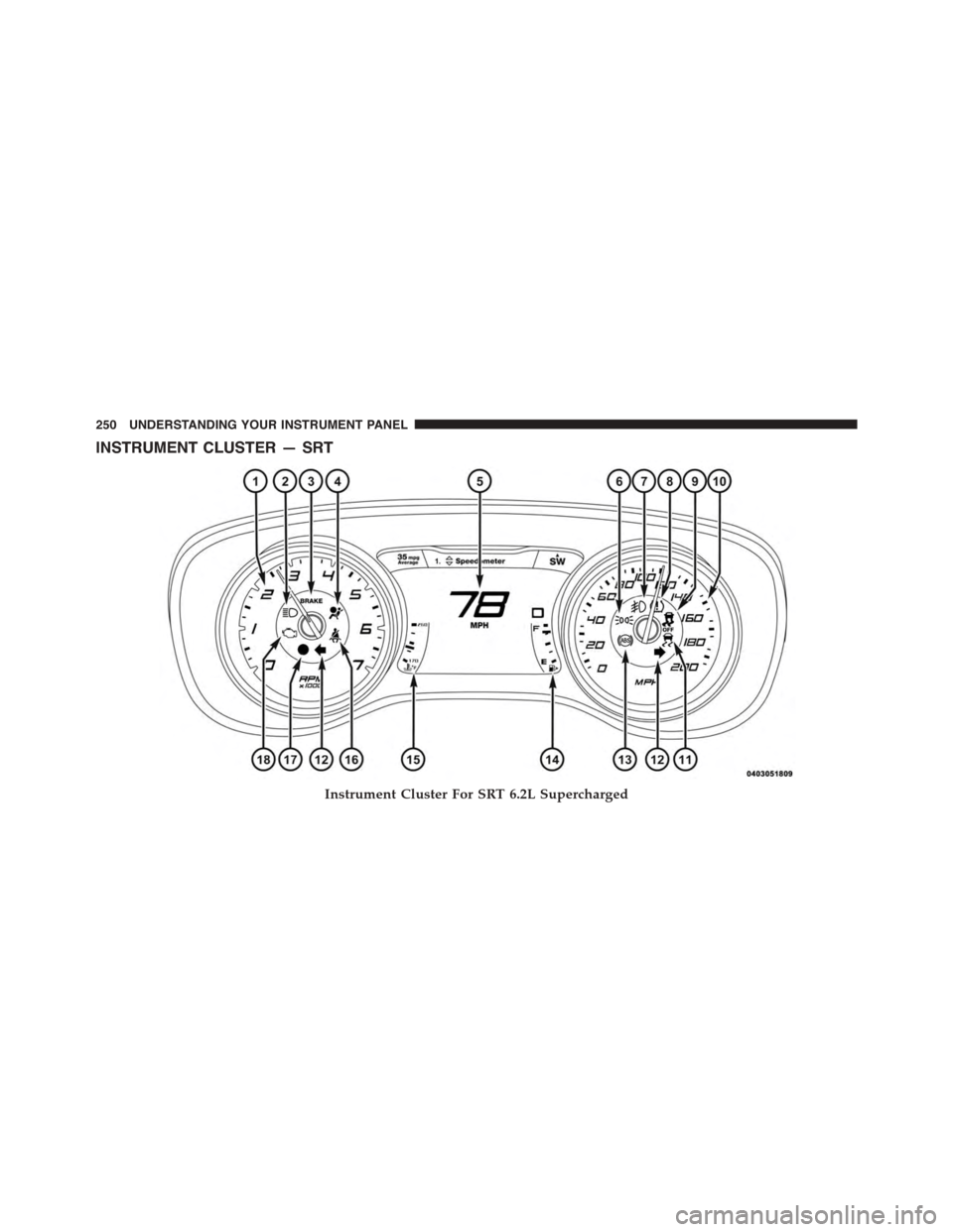
INSTRUMENT CLUSTER — SRT
Instrument Cluster For SRT 6.2L Supercharged
250 UNDERSTANDING YOUR INSTRUMENT PANEL
Page 253 of 595
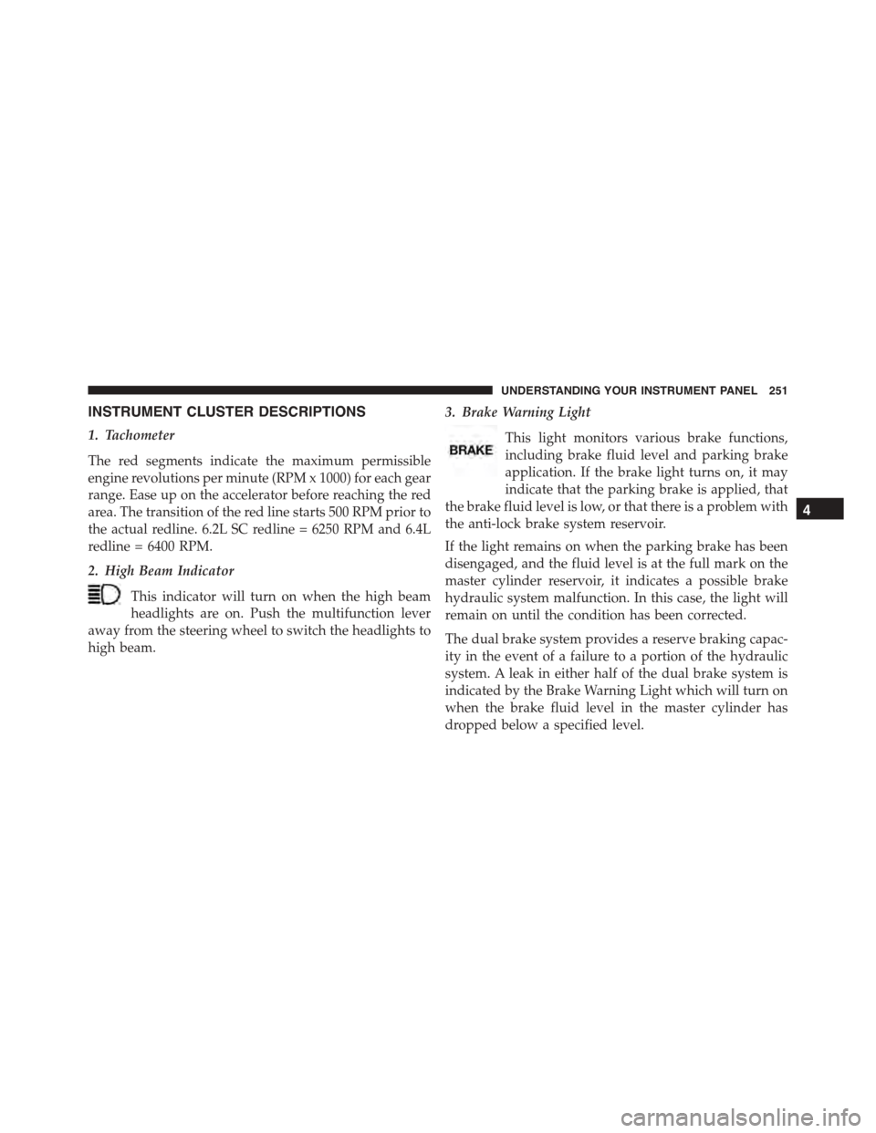
INSTRUMENT CLUSTER DESCRIPTIONS
1. Tachometer
The red segments indicate the maximum permissible
engine revolutions per minute (RPM x 1000) for each gear
range. Ease up on the accelerator before reaching the red
area. The transition of the red line starts 500 RPM prior to
the actual redline. 6.2L SC redline = 6250 RPM and 6.4L
redline = 6400 RPM.
2. High Beam Indicator
This indicator will turn on when the high beam
headlights are on. Push the multifunction lever
away from the steering wheel to switch the headlights to
high beam.
3. Brake Warning Light
This light monitors various brake functions,
including brake fluid level and parking brake
application. If the brake light turns on, it may
indicate that the parking brake is applied, that
the brake fluid level is low, or that there is a problem with
the anti-lock brake system reservoir.
If the light remains on when the parking brake has been
disengaged, and the fluid level is at the full mark on the
master cylinder reservoir, it indicates a possible brake
hydraulic system malfunction. In this case, the light will
remain on until the condition has been corrected.
The dual brake system provides a reserve braking capac-
ity in the event of a failure to a portion of the hydraulic
system. A leak in either half of the dual brake system is
indicated by the Brake Warning Light which will turn on
when the brake fluid level in the master cylinder has
dropped below a specified level.
4
UNDERSTANDING YOUR INSTRUMENT PANEL 251
Page 258 of 595
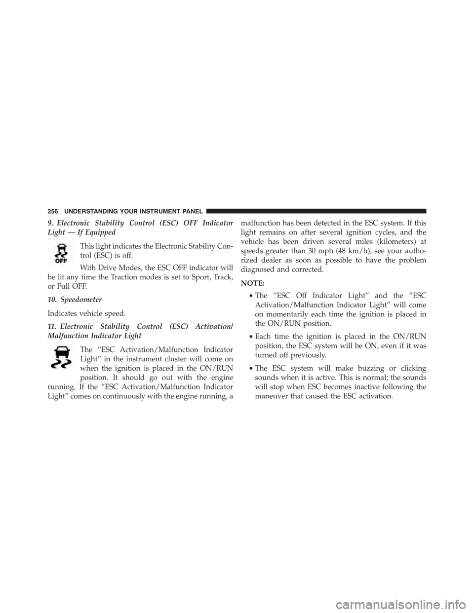
9. Electronic Stability Control (ESC) OFF Indicator
Light — If Equipped
This light indicates the Electronic Stability Con-
trol (ESC) is off.
With Drive Modes, the ESC OFF indicator will
be lit any time the Traction modes is set to Sport, Track,
or Full OFF.
10. Speedometer
Indicates vehicle speed.
11. Electronic Stability Control (ESC) Activation/
Malfunction Indicator Light
The “ESC Activation/Malfunction Indicator
Light” in the instrument cluster will come on
when the ignition is placed in the ON/RUN
position. It should go out with the engine
running. If the “ESC Activation/Malfunction Indicator
Light” comes on continuously with the engine running, a
malfunction has been detected in the ESC system. If this
light remains on after several ignition cycles, and the
vehicle has been driven several miles (kilometers) at
speeds greater than 30 mph (48 km/h), see your autho-
rized dealer as soon as possible to have the problem
diagnosed and corrected.
NOTE:
•The “ESC Off Indicator Light” and the “ESC
Activation/Malfunction Indicator Light” will come
on momentarily each time the ignition is placed in
the ON/RUN position.
•Each time the ignition is placed in the ON/RUN
position, the ESC system will be ON, even if it was
turned off previously.
•The ESC system will make buzzing or clicking
sounds when it is active. This is normal; the sounds
will stop when ESC becomes inactive following the
maneuver that caused the ESC activation.
256 UNDERSTANDING YOUR INSTRUMENT PANEL
Page 262 of 595
WARNING!
A malfunctioning catalytic converter, as referenced
above, can reach higher temperatures than in normal
operating conditions. This can cause a fire if you
drive slowly or park over flammable substances such
as dry plants, wood, cardboard, etc. This could result
in death or serious injury to the driver, occupants or
others.
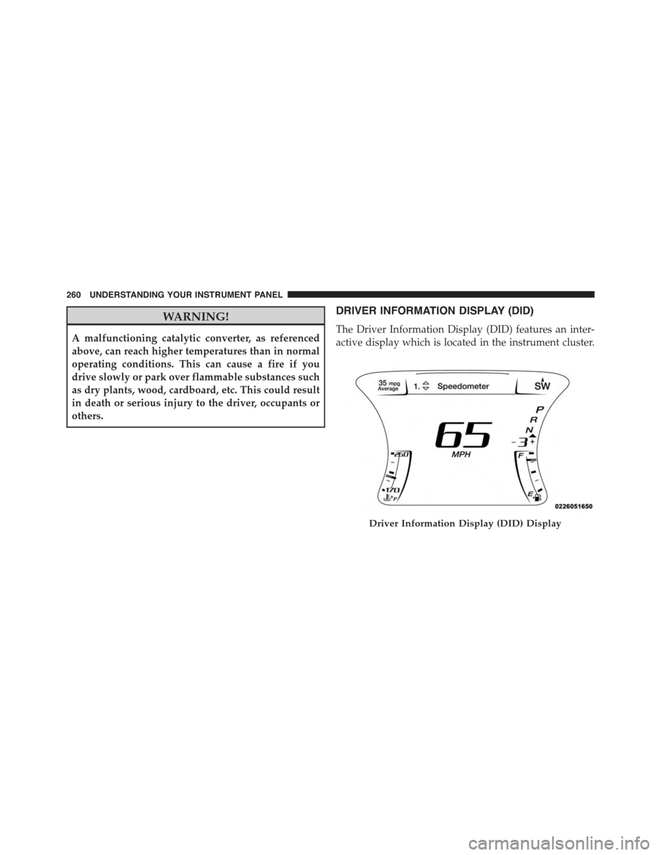
DRIVER INFORMATION DISPLAY (DID)
The Driver Information Display (DID) features an inter-
active display which is located in the instrument cluster.
Driver Information Display (DID) Display
260 UNDERSTANDING YOUR INSTRUMENT PANEL
Page 278 of 595
Top Speed
When selected, this screen displays the Top Speed since
last reset:
•Populates a top speed from first drive cycle and every
time that speed is exceeded that number is stored here
unless/until the driver resets the screen.
•Latching over ignition cycles.
•Units will change with the global change in units.
Driver Assist — If Equipped
Adaptive Cruise Control (ACC) Menu
The DID displays the current ACC system settings. The
information displayed depends on ACC system status.
Push the ADAPTIVE CRUISE CONTROL (ACC) ON/
OFF button (located on the steering wheel) until one of
the following displays in the DID:
Adaptive Cruise Control Off
When ACC is deactivated, the display will read “Adap-
tive Cruise Control Off.”
Adaptive Cruise Control Ready
When ACC is activated but the vehicle speed setting has
not been selected, the display will read “Adaptive Cruise
Control Ready.”
Push the SET + or the SET- button (located on the steering
wheel) and the following will display in the DID:
ACC SET
When ACC is set, the set speed will display in the
instrument cluster.
276 UNDERSTANDING YOUR INSTRUMENT PANEL
Page 280 of 595
•Lower end of gauge will be displayed in an amber
color and turn green as Fuel Economy improves.
•MPG will have the gauge fill from the left (clockwise).
•L/100 km will have the gauge fill from the right
(counter clockwise).
•HoldOKto reset average fuel economy information.
Trip Info
Push and release the UP or DOWN arrow button until
the Trip Menu item is highlighted in the DID (Toggle left
or right to select Trip A or Trip B). The Trip information
will display the following:
•Distance
•Average Fuel Economy
•Elapsed Time
Hold the OK button to reset feature information.
Audio
Push and release the UP or DOWN arrow button until
the Audio Menu displays in the DID.
Stored Messages
Push and release the UP or DOWN arrow button until
the Messages Menu item is highlighted in the DID. This
feature shows the number of stored warning messages.
Pushing the RIGHT arrow button will allow you to see
what the stored messages are.
Screen Setup
Push and release the UP or DOWN arrow button until
the Screen Setup Menu displays in the DID. Push and
release the OK button to enter the sub-menus. The Screen
Setup feature allows you to change what information is
displayed in the instrument cluster as well as the location
that information is displayed.
278 UNDERSTANDING YOUR INSTRUMENT PANEL
Page 286 of 595
•Set Language
When in this display, you may select one of multiple
languages (English / Français / Español) for all display
nomenclature, including the trip functions and the navi-
gation system (if equipped). Press the Set Language
button on the touchscreen, then press the desired lan-
guage button on the touchscreen until a check-mark
appears next to the language, showing that setting has
been selected. Press the back arrow button on the touch-
screen to return to the previous menu.
•Touchscreen Beep
When in this display, you may turn on or shut off the
sound heard when a touchscreen button (button on the
touchscreen) is pressed. Press the “Touchscreen Beep”
button on the touchscreen until a check-mark appears
next to the setting, showing that setting has been se-
lected. Press the back arrow button on the touchscreen to
return to the previous menu.
•Control Screen Time-Out — If Equipped
When this feature is selected, the Controls Screen will
stay open for five seconds before the screen times out.
With the feature deselected, the screen will stay open
until it is manually closed. Press the Control Screen
Time-Out button on the touchscreen until a check-mark
appears next to the setting, showing that setting has been
selected. Press the back arrow button on the touchscreen
to return to the previous menu.
•Navigation Turn-By-Turn In Cluster — If Equipped
When this feature is selected, the turn-by-turn directions
will appear in the display as the vehicle approaches a
designated turn within a programmed route. To make
your selection, press the “Navigation Turn-By-Turn In
Cluster” button on the touchscreen, until a check-mark
appears next to the setting, showing that setting has been
selected. Press the back arrow button on the touchscreen
to return to the previous menu.
284 UNDERSTANDING YOUR INSTRUMENT PANEL
Page 304 of 595
Clear Personal Data
After pressing the “Clear Personal Data Settings” button
on the touchscreen the following settings will be avail-
able:
•Clear Personal Data
When this feature is selected it will remove personal data
including Bluetooth® devices and presets. To remove
personal information, press the “Clear Personal Data”
button and a pop-up will appear asking#Are you sure
you want to clear all personal data?” select “OK” to
Clear, or “Cancel” to exit. Once the data has been cleared,
a pop up appears stating#Personal data cleared”. Press
the back arrow button on the touchscreen to return to the
previous menu.
System Information
After pressing the “System Information” button on the
touchscreen the following information will be available:
•System Information
When System Information is selected, a System Information
screen will appear displaying the system software version.
SRT Performance Pages
Performance Pages is an application that provides a
display for performance indicators, as received from the
Instrument Cluster, that will help you gain familiarity
with the capabilities of your SRT vehicle in real-time.
To access the SRT Performance Pages, press the “SRT &
Apps” button on the touchscreen, then press the “SRT
Performance” button on the touchscreen, or press “SRT
Pages” in the top left of the touchscreen while in Drive
Modes. Press the desired button on the touchscreen to
access that specific Performance Page.
302 UNDERSTANDING YOUR INSTRUMENT PANEL
Page 380 of 595
Only shift from DRIVE to PARK or REVERSE when the
accelerator pedal is released and the vehicle is stopped.
Be sure to keep your foot on the brake pedal when
shifting between these gears.
The transmission shift lever has PARK, REVERSE, NEU-
TRAL, DRIVE, and MANUAL (Autostick) shift positions.
Manual shifts can be made using the Autostick shift
control (refer to “AutoStick” in this section for further
information). Toggling the shift lever forward (-) or
rearward (+) while in the MANUAL (AutoStick) position
(beside the DRIVE position) will manually select the
transmission gear, and will display the current gear in the
instrument cluster as M1, M2, M3, etc.
NOTE:If the shift lever cannot be moved to the PARK,
REVERSE, or NEUTRAL position (when pushed for-
ward) it is probably in the MANUAL (AutoStick, +/-)
position (beside the DRIVE position). In MANUAL
(AutoStick) mode, the transmission gear is displayed in
the instrument cluster (as M1, M2, M3, etc.). Move the
shift lever to the right (into the DRIVE [D] position) for
access to PARK, REVERSE, and NEUTRAL.
Gear Ranges
DO NOT race the engine when shifting from PARK or
NEUTRAL into another gear range.
NOTE:After selecting any gear range, wait a moment to
allow the selected gear to engage before accelerating.
This is especially important when the engine is cold.
PARK (P)
This range supplements the parking brake by locking the
transmission. The engine can be started in this range.
378 STARTING AND OPERATING