climate control DODGE CHARGER SRT 2015 7.G Owners Manual
[x] Cancel search | Manufacturer: DODGE, Model Year: 2015, Model line: CHARGER SRT, Model: DODGE CHARGER SRT 2015 7.GPages: 595, PDF Size: 16.43 MB
Page 99 of 595
Exhaust Gas
WARNING!
Exhaust gases can injure or kill. They contain carbon
monoxide (CO), which is colorless and odorless.
Breathing it can make you unconscious and can
eventually poison you. To avoid breathing (CO),
follow these safety tips:
•Do not run the engine in a closed garage or in
confined areas any longer than needed to move
your vehicle in or out of the area.
•If you are required to drive with the trunk/liftgate/
rear doors open, make sure that all windows are
closed and the climate control BLOWER switch is
set at high speed. DO NOT use the recirculation
mode.
(Continued)
WARNING!(Continued)
•If it is necessary to sit in a parked vehicle with the
engine running, adjust your heating or cooling
controls to force outside air into the vehicle. Set the
blower at high speed.
The best protection against carbon monoxide entry into
the vehicle body is a properly maintained engine exhaust
system.
Whenever a change is noticed in the sound of the exhaust
system, when exhaust fumes can be detected inside the
vehicle, or when the underside or rear of the vehicle is
damaged, have a competent mechanic inspect the com-
plete exhaust system and adjacent body areas for broken,
damaged, deteriorated, or mispositioned parts. Open
seams or loose connections could permit exhaust fumes
to seep into the passenger compartment. In addition,
inspect the exhaust system each time the vehicle is raised
for lubrication or oil change. Replace as required.
2
THINGS TO KNOW BEFORE STARTING YOUR VEHICLE 97
Page 134 of 595
Front Heated Seats
The front heated seats control buttons are located within
the climate or controls screen of the touchscreen.
You can choose from HI, LO or OFF heat settings. The
indicator lights in each switch indicate the level of heat in
use. Two indicator lights will illuminate for HI, one for
LO and none for OFF.
•Press the heated seat buttononce to turn the HI
setting ON.
•Press the heated seat buttona second time to turn
the LO setting ON.
•Press the heated seat buttona third time to turn
the heating elements OFF.
If the HI-level setting is selected, the system will auto-
matically switch to LO-level after approximately 60 min-
utes of continuous operation. At that time, the display
will change from HI to LO, indicating the change. The
LO-level setting will turn OFF automatically after ap-
proximately 45 minutes.
NOTE:
•Once a heat setting is selected, heat will be felt within
two to five minutes.
•The engine must be running for the heated seats to
operate.
Vehicles Equipped With Remote Start
On models that are equipped with remote start, the
heated seats can be programed to come on during a
remote start.
This feature can be programmed through the Uconnect®
system. Refer to “Uconnect® Settings” in “Understand-
ing Your Instrument Panel” for further information.
132 UNDERSTANDING THE FEATURES OF YOUR VEHICLE
Page 136 of 595
Front Ventilated Seats — If Equipped
Located in the seat cushion and seat back are small fans
that draw the air from the passenger compartment and
move air through fine perforations in the seat cover to
help keep the driver and front passenger cooler in higher
ambient temperatures. The fans operate at two speeds,
HI and LO.
The front ventilated seats control buttons are located
within the Uconnect® system. You can gain access to the
control buttons through the climate screen or the controls
screen.
•Press the ventilated seat buttononce to choose HI.
•Press the ventilated seat buttona second time to
choose LO.
•Press the ventilated seat buttona third time to
turn the ventilated seat OFF.
NOTE:The engine must be running for the ventilated
seats to operate.
Vehicles Equipped With Remote Start
On models that are equipped with remote start, the
ventilated seats can be programed to come on during a
remote start.
This feature can be programmed through the Uconnect®
system. Refer to “Uconnect® Settings” in “Understand-
ing Your Instrument Panel” for further information.
Head Restraints
Head restraints are designed to reduce the risk of injury
by restricting head movement in the event of a rear
impact. Head restraints should be adjusted so that the top
of the head restraint is located above the top of your ear.
134 UNDERSTANDING THE FEATURES OF YOUR VEHICLE
Page 164 of 595
HEATED STEERING WHEEL — IF EQUIPPED
The steering wheel contains a heating element that helps
warm your hands in cold weather. The heated steering
wheel has only one temperature setting. Once the heated
steering wheel has been turned on it will operate for up
to 80 minutes before automatically shutting off. The
heated steering wheel can shut off early or may not turn
on when the steering wheel is already warm.
The heated steering wheel control button is located within
the Uconnect® system. You can gain access to the control
button through the climate screen or the controls screen.
•Push the heated steering wheel buttononce to turn
the heating element ON.
•Push the heated steering wheel buttona second
time to turn the heating element OFF.
NOTE:The engine must be running for the heated
steering wheel to operate.
Vehicles Equipped With Remote Start
On models that are equipped with remote start, the
heated steering wheel can be programmed to come on
during a remote start through the Uconnect® system.
Refer to “Uconnect® Settings” in “Understanding Your
Instrument Panel” for further information.
WARNING!
•Persons who are unable to feel pain to the skin
because of advanced age, chronic illness, diabetes,
spinal cord injury, medication, alcohol use, exhaus-
tion, or other physical conditions must exercise
care when using the steering wheel heater. It may
cause burns even at low temperatures, especially if
used for long periods.
(Continued)
162 UNDERSTANDING THE FEATURES OF YOUR VEHICLE
Page 245 of 595
REAR WINDOW FEATURES
Rear Window Defroster
The rear window defroster button is located on
the climate control. Push this button to turn on the
rear window defroster and the heated outside mirrors (if
equipped). An indicator in the button will illuminate
when the rear window defroster is on. The rear window
defroster automatically turns off after approximately 10
minutes. For an additional five minutes of operation,
push the button a second time.
CAUTION!
Failure to follow these cautions can cause damage to
the heating elements:
•Use care when washing the inside of the rear
window. Do not use abrasive window cleaners on
the interior surface of the window. Use a soft cloth
and a mild washing solution, wiping parallel to the
heating elements. Labels can be peeled off after
soaking with warm water.
•Do not use scrapers, sharp instruments, or abrasive
window cleaners on the interior surface of the
window.
•Keep all objects a safe distance from the window.
3
UNDERSTANDING THE FEATURES OF YOUR VEHICLE 243
Page 248 of 595
!Uconnect® RADIOS — IF EQUIPPED........332
!iPod®/USB/MP3 CONTROL..............333
!STEERING WHEEL AUDIO CONTROLS — IF
EQUIPPED...........................334
▫Radio Operation......................335
!RADIO OPERATION AND MOBILE PHONES . .335
▫Regulatory And Safety Information.........335
!CLIMATE CONTROLS...................337
▫Dual Zone Automatic Climate Controls With
Touchscreen.........................338
▫Climate Control Functions...............343
▫Automatic Temperature Control (ATC)......345
▫Operating Tips.......................346
!Uconnect® VOICE RECOGNITION QUICK
TIPS................................350
▫Introducing Uconnect®.................350
▫Get Started..........................351
▫Basic Voice Commands..................352
▫Radio..............................353
▫Media..............................354
▫Phone..............................355
▫Voice Text Reply......................356
▫Climate (8.4A/8.4AN)..................357
▫Navigation (8.4A/8.4AN)................358
▫Uconnect® Access* (8.4A/8.4AN)..........358
▫Register (8.4A/8.4AN)..................359
246 UNDERSTANDING YOUR INSTRUMENT PANEL
Page 250 of 595
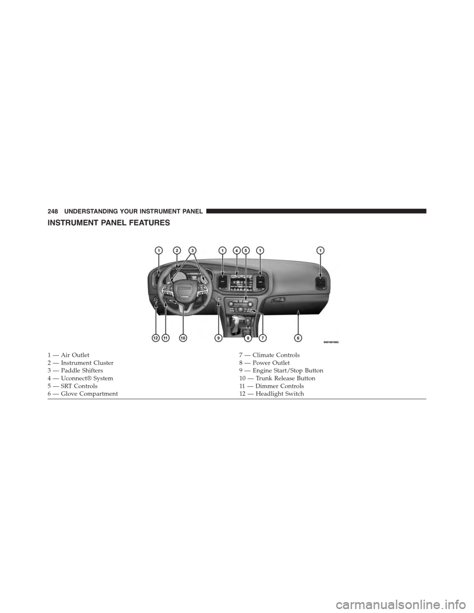
INSTRUMENT PANEL FEATURES
1 — Air Outlet7 — Climate Controls2 — Instrument Cluster8 — Power Outlet3—PaddleShifters9—EngineStart/StopButton4 — Uconnect® System10 — Trunk Release Button5—SRTControls11 — D i m m e r C o n t ro l s6—GloveCompartment12 — Headlight Switch
248 UNDERSTANDING YOUR INSTRUMENT PANEL
Page 339 of 595
NOTE:
•This equipment has been tested and found to comply
with the limits for a Class B digital device, pursuant to
Part 15 of the FCC Rules. These limits are designed to
provide reasonable protection against harmful inter-
ference in a residential installation. This equipment
generates, uses and can radiate radio frequency energy
and, if not installed and used in accordance with the
instructions, may cause harmful interference to radio
communications. However, there is no guarantee that
interference will not occur in a particular installation.
•If this equipment does cause harmful interference to
radio or television reception, which can be determined
by turning the equipment off and on, the user is
encouraged to try to correct the interference by one or
more of the following measures:
•Increase the separation between the equipment and
receiver.
•Consult the dealer or an experienced radio technician
for help.
CLIMATE CONTROLS
The air conditioning and heating system is designed to
make you comfortable in all types of weather. This
system can be operated through either the controls on the
instrument panel or through the Uconnect® system dis-
play.
When the Uconnect® system is in different modes (Ra-
dio, Player, Settings, More, etc.) the driver and passenger
temperature settings will be indicated at the top of the
display.
4
UNDERSTANDING YOUR INSTRUMENT PANEL 337
Page 340 of 595
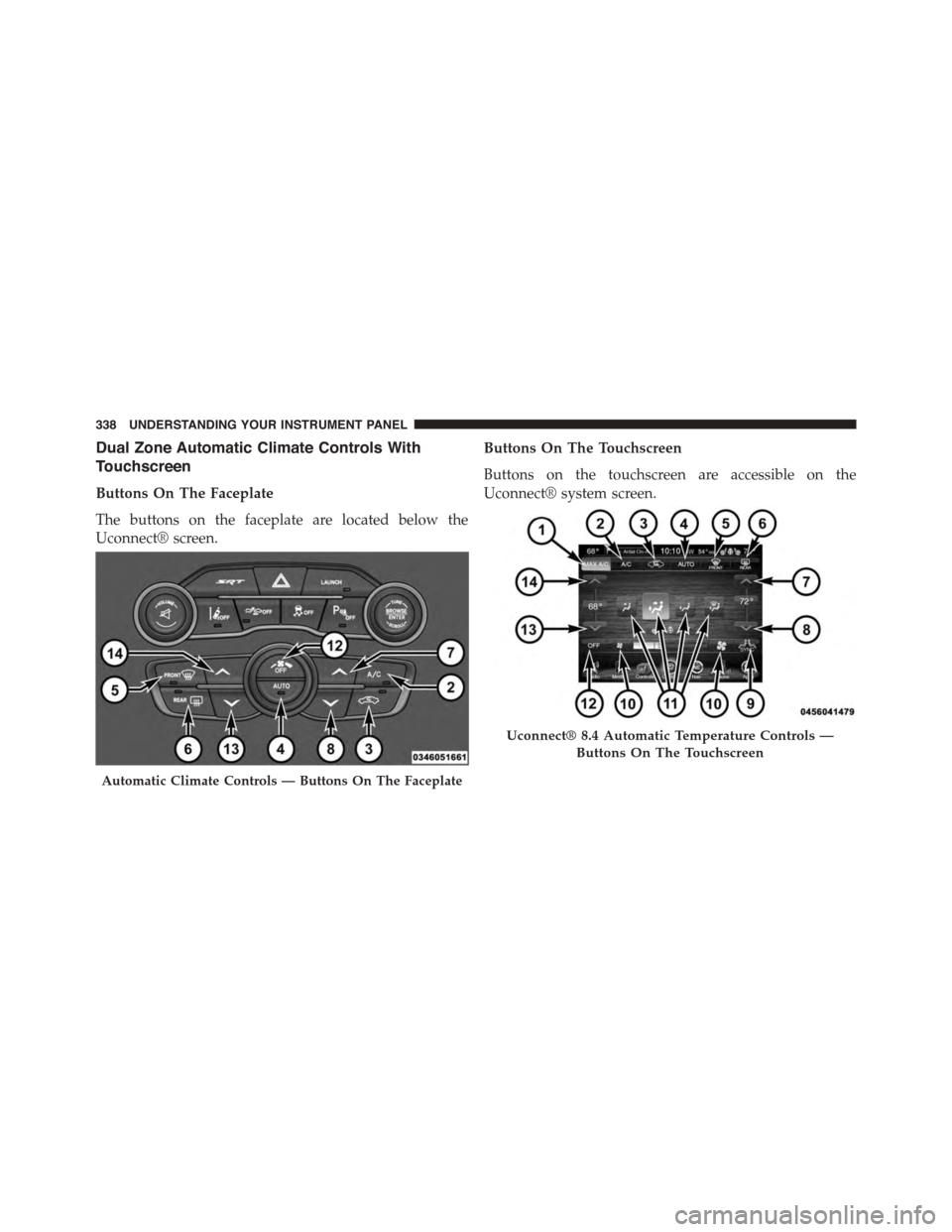
Dual Zone Automatic Climate Controls With
Touchscreen
Buttons On The Faceplate
The buttons on the faceplate are located below the
Uconnect® screen.
Buttons On The Touchscreen
Buttons on the touchscreen are accessible on the
Uconnect® system screen.
Automatic Climate Controls — Buttons On The Faceplate
Uconnect® 8.4 Automatic Temperature Controls —
Buttons On The Touchscreen
338 UNDERSTANDING YOUR INSTRUMENT PANEL
Page 341 of 595
Button Descriptions (Applies To Both Buttons On The
Faceplate And Buttons On The Touchscreen)
1. MAX A/C Button
Press and release to change the current setting, the
indicator illuminates when MAX A/C is ON. Performing
this function again will cause the MAX A/C operation to
switch into manual mode and the MAX A/C indicator
will turn off.
2. A/C Button
Press and release to change the current setting, the
indicator illuminates when A/C is ON. Performing this
function again will cause the A/C operation to switch
into manual mode and the A/C indicator will turn off.
3. Recirculation Button
Press and release to change the current setting, the
indicator illuminates when ON.
4. AUTO Operation Button
Automatically controls the interior cabin temperature by
adjusting airflow distribution and amount. Performing
this function will cause the system to switch between
manual mode and automatic modes. Refer to “Automatic
Operation” for more information.
5. Front Defrost Button
Press and release to change the current airflow setting to
Defrost mode. The indicator illuminates when this fea-
ture is ON. Air comes from the windshield and side
window demist outlets. When the defrost button is
selected, the blower level will increase. Use Defrost mode
with maximum temperature settings for best windshield
and side window defrosting and defogging. Performing
this function will cause the ATC to switch into manual
mode. If the front defrost mode is turned off the climate
system will return the previous setting.
4
UNDERSTANDING YOUR INSTRUMENT PANEL 339