DODGE DAKOTA 2011 3.G Owner's Guide
Manufacturer: DODGE, Model Year: 2011, Model line: DAKOTA, Model: DODGE DAKOTA 2011 3.GPages: 76, PDF Size: 4.62 MB
Page 31 of 76
Auto Door Lock
• To have the doors lock automatically when the vehicle’s speed exceeds15 mph (24 km/h):
• Enter your vehicle and close all the doors.
• Fasten your seatbelt.
• Within 10 seconds, cycle the ignition switch between LOCK and ON and
then back to LOCK four times, ending up in the LOCK position (do not start
the engine).
• Press the power door LOCK switch to lock the doors. A single chime will indicate that programming is complete.
Sound Horn With Lock
• To turn the horn chirp on or off when the doors are locked:
• Press the LOCK button for at least 4 seconds, but no longer than 6 seconds.Then, press the PANIC button while still holding the LOCK button. A single
chime will sound to indicate that this feature has changed.
• Release both buttons at the same time.
Flashing Lights With Lock
• The turn signal lights flashing when the doors are locked or unlocked feature can be turned on or off. To turn this feature on or off:
• Press and hold the UNLOCK button for at least 4 seconds, but no longer
than 6 seconds. Then, press and hold the LOCK button while still holding
the UNLOCK button. A single chime will sound to indicate that this feature
has changed.
• Release both buttons at the same time.
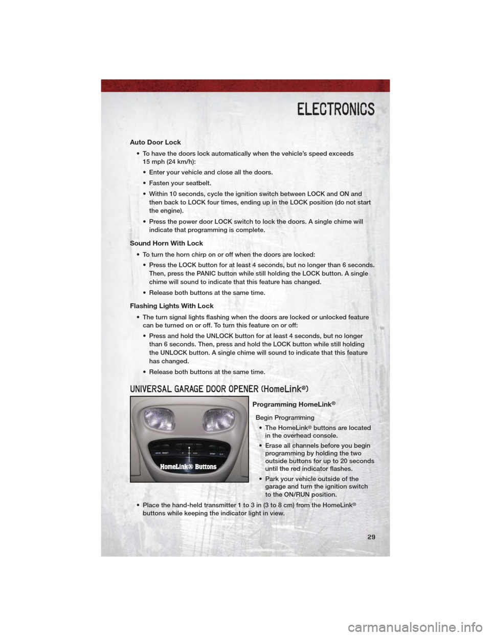
UNIVERSAL GARAGE DOOR OPENER (HomeLink®)
Programming HomeLink®
Begin Programming • The HomeLink
®buttons are located
in the overhead console.
• Erase all channels before you begin programming by holding the two
outside buttons for up to 20 seconds
until the red indicator flashes.
• Park your vehicle outside of the garage and turn the ignition switch
to the ON/RUN position.
• Place the hand-held transmitter 1 to 3 in (3 to 8 cm) from the HomeLink
®
buttons while keeping the indicator light in view.
ELECTRONICS
29
Page 32 of 76
• Simultaneously, press and hold both the chosen HomeLink®button and the
hand-held transmitter button until the HomeLink®indicator flash rate changes
from a slow to a rapidly blinking light, then release both the HomeLink®and
the hand-held transmitter buttons. This may take up to 30 seconds, or longer
in rare cases.
• Press and hold the just-programmed HomeLink
®button; if the indicator light
stays on constantly, programming is complete and the garage door should
open.
NOTE:
• Only use this transceiver with a garage door opener that has a “stop and reverse” feature as required by Federal safety standards. This includes most
garage door opener models manufactured after 1982. Do not use a garage door
opener without these safety features. Call toll-free 1–800–355–3515 or, on the
Internet, at www.HomeLink.com for safety information or assistance.
• If you are having difficulty programming your HomeLink
®and your garage door
opener was manufactured after 1995, you may have a rolling code. Follow the
steps below for Programming A Rolling Code System.
Programming A Rolling Code System • At the garage door opener motor (in the garage), locate the “learn” or “programming” button. This can usually be found where the hanging antenna
wire is attached to the garage door opener motor (it is NOT the button
normally used to open and close the door).
• Firmly press and release the “learn” or “programming” button. The name and color of the button may vary by manufacturer. Within 30 seconds, return to the
vehicle and press the programmed HomeLink
®button twice (holding the
button for two seconds each time). If the device is plugged in and activates,
programming is complete.
• If the device does not activate, press the button a third time (for two seconds) to complete the programming.
Using HomeLink
®
• To operate, simply press and release the programmed HomeLink®button and
the programmed device will operate.
• Refer to your Owner’s Manual on the DVD for further details. If you have any problems programming HomeLink
®, or require assistance, please call toll-free
1–800–355–3515 or, on the Internet, at www.HomeLink.com.
WARNING!
• Your motorized door or gate will open and close while you are programming the universal transceiver. Do not program the transceiver if
people or pets are in the path of the door or gate.
(Continued)
ELECTRONICS
30
Page 33 of 76
WARNING!(Continued)
• Do not run your vehicle in a closed garage or confined area whileprogramming the transceiver. Exhaust gas from your vehicle contains
Carbon Monoxide (CO) which is odorless and colorless. Carbon
Monoxide is poisonous when inhaled and can cause you and others to
be severely injured or killed.
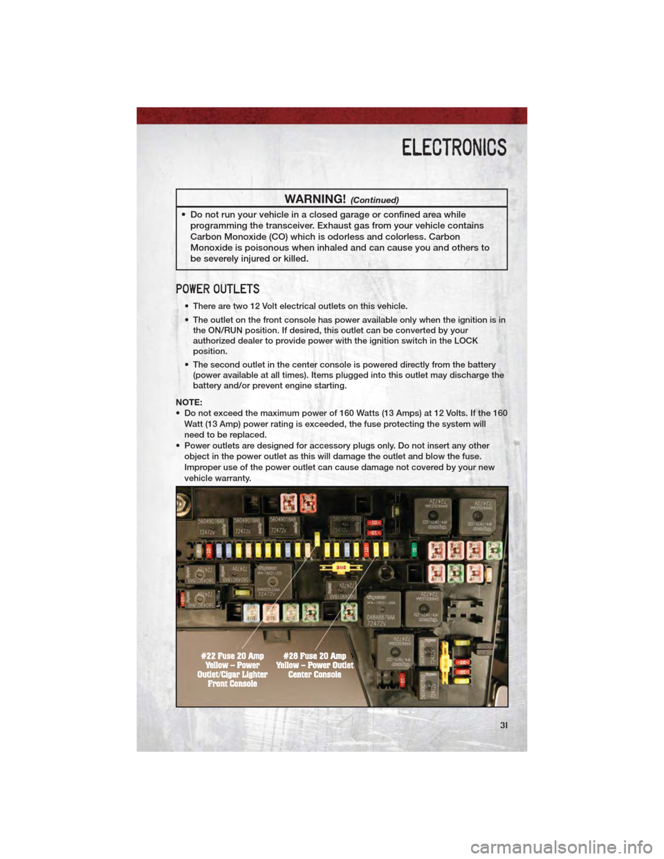
POWER OUTLETS
• There are two 12 Volt electrical outlets on this vehicle.
• The outlet on the front console has power available only when the ignition is inthe ON/RUN position. If desired, this outlet can be converted by your
authorized dealer to provide power with the ignition switch in the LOCK
position.
• The second outlet in the center console is powered directly from the battery (power available at all times). Items plugged into this outlet may discharge the
battery and/or prevent engine starting.
NOTE:
• Do not exceed the maximum power of 160 Watts (13 Amps) at 12 Volts. If the 160 Watt (13 Amp) power rating is exceeded, the fuse protecting the system will
need to be replaced.
• Power outlets are designed for accessory plugs only. Do not insert any other object in the power outlet as this will damage the outlet and blow the fuse.
Improper use of the power outlet can cause damage not covered by your new
vehicle warranty.
ELECTRONICS
31
Page 34 of 76
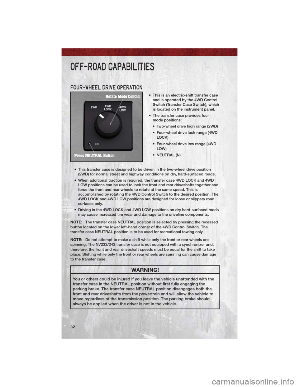
FOUR-WHEEL DRIVE OPERATION
• This is an electric-shift transfer caseand is operated by the 4WD Control
Switch (Transfer Case Switch), which
is located on the instrument panel.
• The transfer case provides four mode positions:
• Two-wheel drive high range (2WD)
• Four-wheel drive lock range (4WD
LOCK)
• Four-wheel drive low range (4WD LOW)
• NEUTRAL (N)
• This transfer case is designed to be driven in the two-wheel drive position (2WD) for normal street and highway conditions on dry, hard-surfaced roads.
• When additional traction is required, the transfer case 4WD LOCK and 4WD LOW positions can be used to lock the front and rear driveshafts together and
force the front and rear wheels to rotate at the same speed. This is
accomplished by rotating the 4WD Control Switch to the desired position. The
4WD LOCK and 4WD LOW positions are designed for loose or slippery road
surfaces only.
• Driving in the 4WD LOCK and 4WD LOW positions on dry hard-surfaced roads may cause increased tire wear and damage to the driveline components.
NOTE: The transfer case NEUTRAL position is selected by pressing the recessed
button located on the lower left-hand corner of the 4WD Control Switch. The
transfer case NEUTRAL position is to be used for recreational towing only.
NOTE: Do not attempt to make a shift while only the front or rear wheels are
spinning. The NV233/243 transfer case is not equipped with a synchronizer and,
therefore, the front and rear driveshaft speeds must be equal for the shift to take
place. Shifting while only the front or rear wheels are spinning can cause damage
to the transfer case.
WARNING!
You or others could be injured if you leave the vehicle unattended with the
transfer case in the NEUTRAL position without first fully engaging the
parking brake. The transfer case NEUTRAL position disengages both the
front and rear driveshafts from the powertrain and will allow the vehicle to
move regardless of the transmission position. The parking brake should
always be applied when the driver is not in the vehicle.
OFF-ROAD CAPABILITIES
32
Page 35 of 76
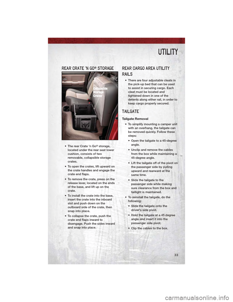
REAR CRATE 'N GO®STORAGE
• The rear Crate 'n Go®storage,
located under the rear seat lower
cushion, consists of two
removable, collapsible storage
crates.
• To open the crates, lift upward on the crate handles and engage the
crate end flaps.
• To remove the crate, press on the release lever, located on the ends
of the base, and lift up on the
crate.
• To install the crate into the base, insert the crate into the inboard
slot and push down on the
outboard side of the crate, then
snap into place.
• To collapse the crate, push the crate end flaps inward to
disengage. Push the sides inward
and snap into place.
REAR CARGO AREA UTILITY
RAILS
• There are four adjustable cleats inthe pick-up bed that can be used
to assist in securing cargo. Each
cleat must be located and
tightened down in one of the
detents along either rail, in order to
keep cargo properly secured.
TAILGATE
Tailgate Removal
• To simplify mounting a camper unitwith an overhang, the tailgate can
be removed quickly. Follow these
steps:
• Open the tailgate to a 45-degree
angle.
• Unclip and remove the cables from the box while maintaining a
45-degree angle.
• Lift the tailgate off of the pivot on the passenger side by pulling
upward and rearward at the
same time.
• Slide the tailgate to the passenger side while making
sure clearance from the box and
taillight is maintained.
• To reinstall the tailgate, do the following:
• Slide the tailgate onto the
driver's side pivot.
• Hold the tailgate at a 45 degree angle and insert it into the
passenger side pivot.
• Clip the cables to the box.
UTILITY
33
Page 36 of 76
Two–Position Tailgate/Upper Load
Platform
• Your tailgate can be opened to thefull-open or the partial-open
position. The partial-open position
is for loading objects longer than
the length of the bed (sheets of
plywood, etc.) by creating an upper
load platform.
Installing Lumber • Place lumber across the box in the indentations provided above the
wheel housings and in the
bulkhead dividers, to form the floor.
There are indents in the sheet
metal (or bed liner if equipped) on
the inner side of the box in front
(Crew Cab
®only) and behind both
wheel housings.
• Secure the tailgate in the partially-open position.
• Open the tailgate slightly.
• Snap the tailgate support cable between the cable guide and the
tailgate bumper. Do this on both
sides of the tailgate.
• To return the tailgate to the full-open position:
• Lift up on tailgate.
• Remove both cables from
between the cable guides and
the tailgate bumpers, and lower
the tailgate.
CAUTION!
• Care should always beexercised when operating a
vehicle with cargo. Vehicle
speeds may need to be
reduced. Severe turns or rough
roads may cause shifting or
bouncing of the cargo that may
result in vehicle damage.
(Continued)
CAUTION!(Continued)
• Ensure the load is securely tieddown and is properly identified
according to local laws if it
extends beyond the tail lights.
• Loading should not exceed 400 lbs (181 kg) of material
suspended above the
wheelhouse and partially open
tailgate or vehicle damage may
result.
TRAILER TOWING WEIGHTS
(MAXIMUM TRAILER WEIGHT
RATINGS)
NOTE: For trailer towing information
(maximum trailer weight ratings) refer to
the following website addresses:
• http:// www.ramtrucks.com/towing
• http:// www.ramtruck.ca (Canada)
RECREATIONAL TOWING
(BEHIND MOTORHOME, ETC.)
Two-Wheel Drive Models
• Recreational towing of two-wheel
drive models is not allowable.
Towing the vehicle with the
transmission in NEUTRAL can
cause severe transmission
damage. Removal of the driveshaft
for towing is not recommended,
since this would allow fluid to drain
from the transmission.
UTILITY
34
Page 37 of 76
Four-Wheel Drive Models
Recreational Towing Procedure• Use the following procedure to prepare your vehicle for
recreational towing.
• Bring the vehicle to a complete
stop, shut the engine OFF and
turn the Key Fob to the ON/RUN
position (do not start the engine).
• Press the brake pedal and shift the automatic transmission into
NEUTRAL, or press the clutch
pedal to the floor on a manual
transmission.
• Using a ballpoint pen or similar object, press the transfer case
NEUTRAL button for four
seconds.
• After the shift is completed and the NEUTRAL light comes on,
release the NEUTRAL button.
• Start the engine and shift the automatic transmission into
REVERSE.
• Release the brake pedal for five seconds and ensure that there is
no vehicle movement.
• Repeat the previous step with the transmission in DRIVE.
• Shut the engine OFF, and place the Key Fob in the unlocked OFF
position.
• Shift automatic transmissions into PARK. Shift manual
transmissions into fourth gear.
• Attach the vehicle to the tow vehicle with a tow bar and
disconnect the negative battery
cable.
• Refer to your Owner's Manual on the DVD for further details. NOTE:
• The first two steps are requirements
that must be met prior to pressing
the NEUTRAL button, and must
continue to be met until the four
seconds elapse and the shift has
been completed. If any of these
requirements (with the exception of
Key Fob ON) are not met prior to
pressing the NEUTRAL button or are
no longer met during the four second
timer, then the NEUTRAL indicator
light will flash continuously until all
requirements are met or until the
NEUTRAL button is released.
• The Key Fob must be ON for a shift to take place and for the position
indicator lights to be operable. If the
Key Fob in not ON, the shift will not
take place and no position indicator
lights will be on or flashing.
• A flashing NEUTRAL position indicator light indicates that shift
requirements have not been met.
CAUTION!
• Internal damage to the transfercase will occur if a front or rear
wheel lift is used when
recreational towing.
• The transfer case must be shifted into NEUTRAL for
recreational towing. The
NEUTRAL button is located on
the lower left hand corner of the
4WD Control Switch. Shifts into
and out of transfer case
NEUTRAL can take place with
the selector switch in any mode
position.
• Automatic transmissions must be placed in PARK position for
recreational towing.
(Continued)
UTILITY
35
Page 38 of 76
CAUTION!(Continued)
• Manual transmissions must beplaced in gear (for example,
fourth gear) for recreational
towing. Failure to follow these
procedures can cause severe
transmission and/or transfer
case damage.
• It is necessary to follow these steps to be certain that the
transfer case is fully in
NEUTRAL before recreational
towing to prevent damage to
internal parts.
BRAKE/TRANSMISSION
INTERLOCK SYSTEM
• This system prevents you from
moving the shift lever out of PARK
and into any gear unless the brake
pedal is pressed.
• This system is active only when the ignition switch is in the ON/RUN
position.
UTILITY
36
Page 39 of 76
24-HOUR TOWING ASSISTANCE
• Dial toll-free 1-800-521-2779 or 1-800-363-4869 for Canadian residents.
• Provide your name, vehicle identification number and license plate number.
• Provide your location, including telephone number, from which you are calling.
• Briefly describe the nature of the problem and answer a few simple questions.
• You will be given the name of the service provider and an estimated time ofarrival. If you feel you are in an “unsafe situation”, please let us know. With
your consent, we will contact local police or safety authorities.
INSTRUMENT CLUSTER WARNING LIGHTS
- Tire Pressure Monitoring System (TPMS) Light
• Each tire, including the spare (if provided), should be checked monthly, whencold and inflated to the inflation pressure recommended by the vehicle
manufacturer on the vehicle placard or tire inflation pressure label. (If your
vehicle has tires of a different size than the size indicated on the vehicle
placard or tire inflation pressure label, you should determine the proper tire
inflation pressure for those tires.)
• As an added safety feature, your vehicle has been equipped with a Tire Pressure Monitoring System (TPMS) that illuminates a low tire pressure telltale
when one or more of your tires is significantly under-inflated. Accordingly,
when the low tire pressure telltale illuminates, you should stop and check your
tires as soon as possible, and inflate them to the proper pressure. Driving on a
significantly under-inflated tire causes the tire to overheat and can lead to tire
failure. Under-inflation also reduces fuel efficiency and tire tread life, and may
affect the vehicle’s handling and stopping ability.
• IF THE LIGHT STARTS FLASHING INDICATING A LOW TIRE PRESSURE,
ADJUST THE AIR PRESSURE IN THE LOW TIRE TO THE AIR PRESSURE
SHOWN ON THE VEHICLE PLACARD OR TIRE INFLATION PRESSURE
LABEL LOCATED ON THE DRIVER'S DOOR. NOTE: AFTER INFLATION, THE
VEHICLE MAY NEED TO BE DRIVEN FOR 20 MINUTES BEFORE THE
FLASHING LIGHT WILL TURN OFF.
• Please note that the TPMS is not a substitute for proper tire maintenance, and it is the driver’s responsibility to maintain correct tire pressure, even if
under-inflation has not reached the level to trigger illumination of the TPMS
low tire pressure telltale.
• Your vehicle has also been equipped with a TPMS malfunction indicator to indicate when the system is not operating properly. The TPMS malfunction
indicator is combined with the low tire pressure telltale. When the system
detects a malfunction, the telltale will flash for approximately one minute and
then remain continuously illuminated. This sequence will continue each time
the vehicle is restarted as long as the malfunction exists.
WHAT TO DO IN EMERGENCIES
37
Page 40 of 76
• When the malfunction indicator is illuminated, the system may not be able todetect or signal low tire pressure as intended. TPMS malfunctions may occur
for a variety of reasons, including the installation of replacement or alternate
tires or wheels on the vehicle that prevent the TPMS from functioning properly.
Always check the TPMS malfunction telltale after replacing one or more tires
or wheels on your vehicle, to ensure that the replacement or alternate tires and
wheels allow the TPMS to continue to function properly.
CAUTION!
The TPMS has been optimized for the original equipment tires and wheels.
TPMS pressures and warning have been established for the tire size
equipped on your vehicle. Undesirable system operation or sensor damage
may result when using replacement equipment that is not of the same size,
type, and/or style. Aftermarket wheels can cause sensor damage. Do not
use tire sealant from a can, or balance beads if your vehicle is equipped
with a TPMS, as damage to the sensors may result.
- Engine Temperature Warning Light
• This light warns of an overheated engine condition.
• If the light turns on and a warning chime sounds while driving, safely pull overand stop the vehicle. If the A/C system is on, turn it off. Also, shift the
transmission into NEUTRAL and idle the vehicle. If the temperature reading
does not return to normal, turn the engine off immediately.
• We recommend that you do not operate the vehicle or engine damage will occur. Have the vehicle serviced immediately.
WARNING!
A hot engine cooling system is dangerous. You or others could be badly
burned by steam or boiling coolant. You may want to call an authorized
service center for service if your vehicle overheats.
BRAKE- Brake Warning Light
• The Brake Warning light illuminates when there is either a system malfunctionor the parking brake is applied. If the light is on and the parking brake is not
applied, it indicates a possible brake hydraulic malfunction, brake booster
problem or an Anti-Lock Brake System problem.
• We recommend you drive to the nearest service center and have the vehicle serviced immediately.
WHAT TO DO IN EMERGENCIES
38