light DODGE DAKOTA 2011 3.G User Guide
[x] Cancel search | Manufacturer: DODGE, Model Year: 2011, Model line: DAKOTA, Model: DODGE DAKOTA 2011 3.GPages: 76, PDF Size: 4.62 MB
Page 3 of 76
INTRODUCTION/WELCOME
Welcome From Chrysler Group LLC . . . 2
CONTROLS AT A GLANCE
Driver Cockpit...............4
Instrument Cluster ............6
GETTING STARTED
KeyFOB ..................8
Remote Start................8
Theft Alarm ................9
Seat Belt ..................9
Supplemental Restraint System (SRS) —
Airbags .................. 10
Child Restraints ............. 11
Front Seats ................ 14
Heated Seats .............. 16
Tilt Steering Column .......... 17
OPERATING YOUR VEHICLE
Turn Signals/Wiper/Washer/High
Beams Lever............... 18
Headlight Switch ............ 19
Speed Control .............. 20
Climate Controls ............. 21
Wind Buffeting .............. 21
ELECTRONICS
Non-Touch-Screen Radios ....... 22
Steering Wheel Audio Controls .... 25
Uconnect™ Phone ........... 25
Uconnect™ Voice Command ...... 27
Programmable Features ........ 28
Universal Garage Door Opener
(HomeLink
®)............... 29
Power Outlets .............. 31
OFF-ROAD CAPABILITIES
Four-Wheel Drive Operation ...... 32
UTILITY
Rear Crate 'N Go®Storage....... 33 Rear Cargo Area Utility Rails
...... 33
Tailgate .................. 33
Trailer Towing Weights (Maximum
Trailer Weight Ratings) ......... 34
Recreational Towing (Behind
Motorhome, Etc.) ............ 34
Brake/Transmission Interlock
System .................. 36
WHAT TO DO IN EMERGENCIES
24-Hour Towing Assistance ...... 37
Instrument Cluster Warning Lights . . 37
If Your Engine Overheats ........ 40
Jacking And Tire Changing ....... 42
Jump-Starting .............. 47
Emergency Tow Hooks ......... 49
Towing A Disabled Vehicle ....... 50
Freeing A Stuck Vehicle ......... 51
Event Data Recorder (EDR) ....... 52
MAINTAINING YOUR VEHICLE
Opening The Hood........... 53
Engine Compartment .......... 54
Fluids And Capacities .......... 56
Maintenance Chart ........... 58
Fuses ................... 61
Tire Pressures .............. 64
Wheel And Wheel Trim Care ...... 64
Exterior Bulbs .............. 65
CONSUMER ASSISTANCE
Chrysler Group LLC Customer Center . 66
Chrysler Canada Inc. Customer Center 66
Assistance For The Hearing Impaired . 66
Publications Ordering .......... 66
Reporting Safety Defects In
The 50 United States And
Washington, D.C. ............ 67
MOPAR ACCESSORIES
Authentic Accessories By MOPAR®.. 68
INDEX.................. 69
TABLE OF CONTENTS
Page 8 of 76
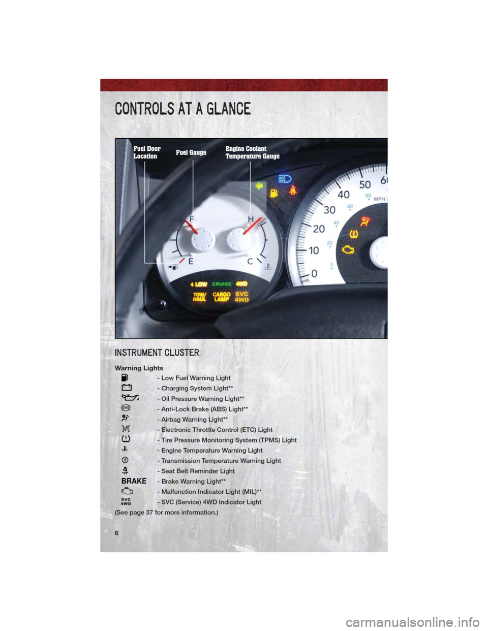
INSTRUMENT CLUSTER
Warning Lights
- Low Fuel Warning Light
- Charging System Light**
- Oil Pressure Warning Light**
- Anti-Lock Brake (ABS) Light**
- Airbag Warning Light**
- Electronic Throttle Control (ETC) Light
- Tire Pressure Monitoring System (TPMS) Light
- Engine Temperature Warning Light
- Transmission Temperature Warning Light
- Seat Belt Reminder Light
BRAKE- Brake Warning Light**
- Malfunction Indicator Light (MIL)**
- SVC (Service) 4WD Indicator Light
(See page 37 for more information.)
CONTROLS AT A GLANCE
6
Page 9 of 76
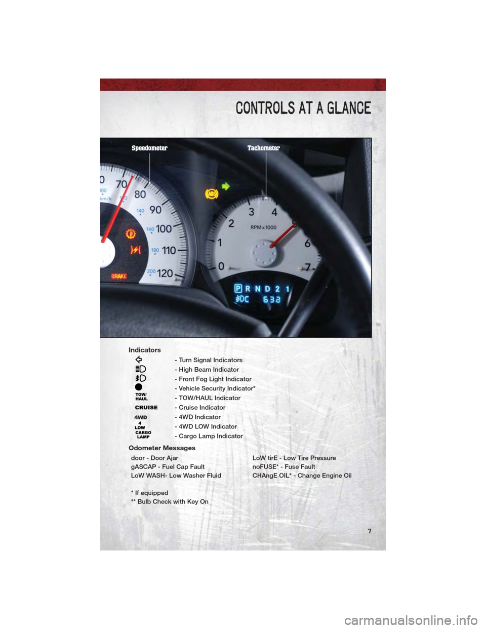
Indicators
- Turn Signal Indicators
- High Beam Indicator
- Front Fog Light Indicator
- Vehicle Security Indicator*
- TOW/HAUL Indicator
- Cruise Indicator
- 4WD Indicator
- 4WD LOW Indicator
- Cargo Lamp Indicator
Odometer Messages
door - Door AjarLoW tirE - Low Tire Pressure
gASCAP - Fuel Cap Fault noFUSE* - Fuse Fault
LoW WASH- Low Washer Fluid CHAngE OIL* - Change Engine Oil
* If equipped
** Bulb Check with Key On
CONTROLS AT A GLANCE
7
Page 12 of 76
WARNING!
In a collision, you and your passengers can suffer much greater injuries if
you are not buckled up properly. You can strike the interior of your vehicle
or other passengers, or you can be thrown out of the vehicle. Always be
sure you and others in your vehicle are buckled up properly.
SUPPLEMENTAL RESTRAINT SYSTEM (SRS) — AIRBAGS
• This vehicle has Advanced Front Airbags for both the driver and right frontpassenger as a supplement to the seat belt restraint system. The Advanced
Front Airbags will not deploy in every type of collision.
• Advanced Front Airbags are designed to provide additional protection by supplementing the seat belts in certain frontal collisions depending on the
severity and type of collision. Advanced Front Airbags are not expected to
reduce the risk of injury in rear, side, or rollover collisions.
• This vehicle may be equipped with Supplemental Side Airbag Inflatable Curtains to protect the driver, front and rear passengers sitting next to a
window.
• If the Airbag Warning Light
is not on during starting, stays on, or turns on
while driving, have the vehicle serviced by an authorized service center
immediately.
• Refer to the Owner's Manual on the DVD for further details regarding the Supplemental Restraint System (SRS).
WARNING!
• Relying on the airbags alone could lead to more severe injuries in acollision. The airbags work with your seat belt to restrain you properly. In
some collisions, the airbags won't deploy at all. Always wear your seat
belts even though you have airbags.
• Being too close to the steering wheel or instrument panel during Advanced Front Airbag deployment could cause serious injury, including
death. Airbags need room to inflate. Sit back, comfortably extending your
arms to reach the steering wheel or instrument panel.
• Supplemental Side Airbag Inflatable Curtains need room to inflate. Do not lean against the door or window. Sit upright in the center of the seat.
• Being too close to the Supplemental Side Airbag Inflatable Curtain during deployment could cause you to be severely injured or killed.
• Do not drive your vehicle after the airbags have deployed. If you are involved in another collision, the airbags will not be in place to protect
you.
• After any collision, the vehicle should be taken to an authorized dealer immediately.
GETTING STARTED
10
Page 17 of 76
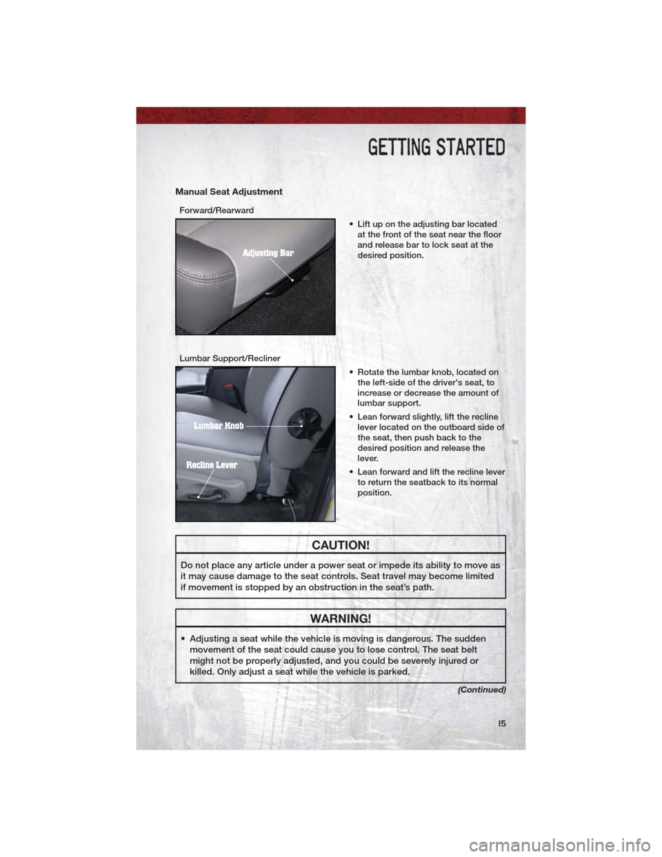
Manual Seat Adjustment
Forward/Rearward• Lift up on the adjusting bar locatedat the front of the seat near the floor
and release bar to lock seat at the
desired position.
Lumbar Support/Recliner • Rotate the lumbar knob, located onthe left-side of the driver's seat, to
increase or decrease the amount of
lumbar support.
• Lean forward slightly, lift the recline lever located on the outboard side of
the seat, then push back to the
desired position and release the
lever.
• Lean forward and lift the recline lever to return the seatback to its normal
position.
CAUTION!
Do not place any article under a power seat or impede its ability to move as
it may cause damage to the seat controls. Seat travel may become limited
if movement is stopped by an obstruction in the seat’s path.
WARNING!
• Adjusting a seat while the vehicle is moving is dangerous. The suddenmovement of the seat could cause you to lose control. The seat belt
might not be properly adjusted, and you could be severely injured or
killed. Only adjust a seat while the vehicle is parked.
(Continued)
GETTING STARTED
15
Page 20 of 76
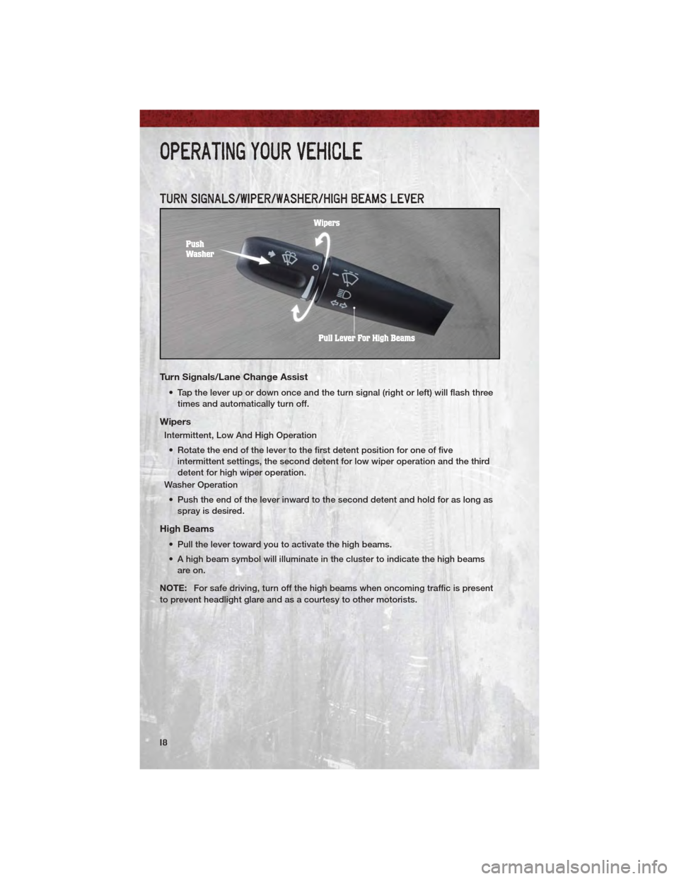
TURN SIGNALS/WIPER/WASHER/HIGH BEAMS LEVER
Turn Signals/Lane Change Assist
• Tap the lever up or down once and the turn signal (right or left) will flash threetimes and automatically turn off.
Wipers
Intermittent, Low And High Operation
• Rotate the end of the lever to the first detent position for one of five intermittent settings, the second detent for low wiper operation and the third
detent for high wiper operation.
Washer Operation
• Push the end of the lever inward to the second detent and hold for as long as spray is desired.
High Beams
• Pull the lever toward you to activate the high beams.
• A high beam symbol will illuminate in the cluster to indicate the high beamsare on.
NOTE: For safe driving, turn off the high beams when oncoming traffic is present
to prevent headlight glare and as a courtesy to other motorists.
OPERATING YOUR VEHICLE
18
Page 21 of 76
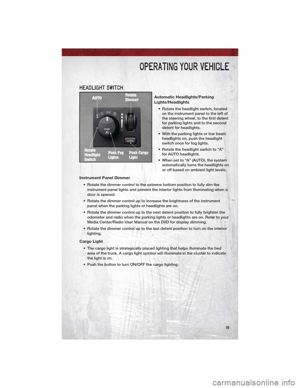
HEADLIGHT SWITCH
Automatic Headlights/Parking
Lights/Headlights
• Rotate the headlight switch, locatedon the instrument panel to the left of
the steering wheel, to the first detent
for parking lights and to the second
detent for headlights.
• With the parking lights or low beam headlights on, push the headlight
switch once for fog lights.
• Rotate the headlight switch to “A” for AUTO headlights.
• When set to “A” (AUTO), the system automatically turns the headlights on
or off based on ambient light levels.
Instrument Panel Dimmer
• Rotate the dimmer control to the extreme bottom position to fully dim the
instrument panel lights and prevent the interior lights from illuminating when a
door is opened.
• Rotate the dimmer control up to increase the brightness of the instrument panel when the parking lights or headlights are on.
• Rotate the dimmer control up to the next detent position to fully brighten the odometer and radio when the parking lights or headlights are on. Refer to your
Media Center/Radio User Manual on the DVD for display dimming.
• Rotate the dimmer control up to the last detent position to turn on the interior lighting.
Cargo Light
• The cargo light is strategically placed lighting that helps illuminate the bedarea of the truck. A cargo light symbol will illuminate in the cluster to indicate
the light is on.
• Push the button to turn ON/OFF the cargo lighting.
OPERATING YOUR VEHICLE
19
Page 31 of 76
Auto Door Lock
• To have the doors lock automatically when the vehicle’s speed exceeds15 mph (24 km/h):
• Enter your vehicle and close all the doors.
• Fasten your seatbelt.
• Within 10 seconds, cycle the ignition switch between LOCK and ON and
then back to LOCK four times, ending up in the LOCK position (do not start
the engine).
• Press the power door LOCK switch to lock the doors. A single chime will indicate that programming is complete.
Sound Horn With Lock
• To turn the horn chirp on or off when the doors are locked:
• Press the LOCK button for at least 4 seconds, but no longer than 6 seconds.Then, press the PANIC button while still holding the LOCK button. A single
chime will sound to indicate that this feature has changed.
• Release both buttons at the same time.
Flashing Lights With Lock
• The turn signal lights flashing when the doors are locked or unlocked feature can be turned on or off. To turn this feature on or off:
• Press and hold the UNLOCK button for at least 4 seconds, but no longer
than 6 seconds. Then, press and hold the LOCK button while still holding
the UNLOCK button. A single chime will sound to indicate that this feature
has changed.
• Release both buttons at the same time.
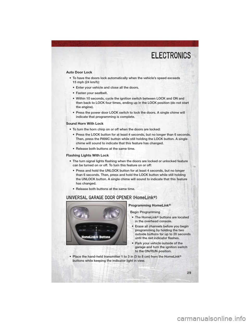
UNIVERSAL GARAGE DOOR OPENER (HomeLink®)
Programming HomeLink®
Begin Programming • The HomeLink
®buttons are located
in the overhead console.
• Erase all channels before you begin programming by holding the two
outside buttons for up to 20 seconds
until the red indicator flashes.
• Park your vehicle outside of the garage and turn the ignition switch
to the ON/RUN position.
• Place the hand-held transmitter 1 to 3 in (3 to 8 cm) from the HomeLink
®
buttons while keeping the indicator light in view.
ELECTRONICS
29
Page 32 of 76
• Simultaneously, press and hold both the chosen HomeLink®button and the
hand-held transmitter button until the HomeLink®indicator flash rate changes
from a slow to a rapidly blinking light, then release both the HomeLink®and
the hand-held transmitter buttons. This may take up to 30 seconds, or longer
in rare cases.
• Press and hold the just-programmed HomeLink
®button; if the indicator light
stays on constantly, programming is complete and the garage door should
open.
NOTE:
• Only use this transceiver with a garage door opener that has a “stop and reverse” feature as required by Federal safety standards. This includes most
garage door opener models manufactured after 1982. Do not use a garage door
opener without these safety features. Call toll-free 1–800–355–3515 or, on the
Internet, at www.HomeLink.com for safety information or assistance.
• If you are having difficulty programming your HomeLink
®and your garage door
opener was manufactured after 1995, you may have a rolling code. Follow the
steps below for Programming A Rolling Code System.
Programming A Rolling Code System • At the garage door opener motor (in the garage), locate the “learn” or “programming” button. This can usually be found where the hanging antenna
wire is attached to the garage door opener motor (it is NOT the button
normally used to open and close the door).
• Firmly press and release the “learn” or “programming” button. The name and color of the button may vary by manufacturer. Within 30 seconds, return to the
vehicle and press the programmed HomeLink
®button twice (holding the
button for two seconds each time). If the device is plugged in and activates,
programming is complete.
• If the device does not activate, press the button a third time (for two seconds) to complete the programming.
Using HomeLink
®
• To operate, simply press and release the programmed HomeLink®button and
the programmed device will operate.
• Refer to your Owner’s Manual on the DVD for further details. If you have any problems programming HomeLink
®, or require assistance, please call toll-free
1–800–355–3515 or, on the Internet, at www.HomeLink.com.
WARNING!
• Your motorized door or gate will open and close while you are programming the universal transceiver. Do not program the transceiver if
people or pets are in the path of the door or gate.
(Continued)
ELECTRONICS
30
Page 35 of 76
REAR CRATE 'N GO®STORAGE
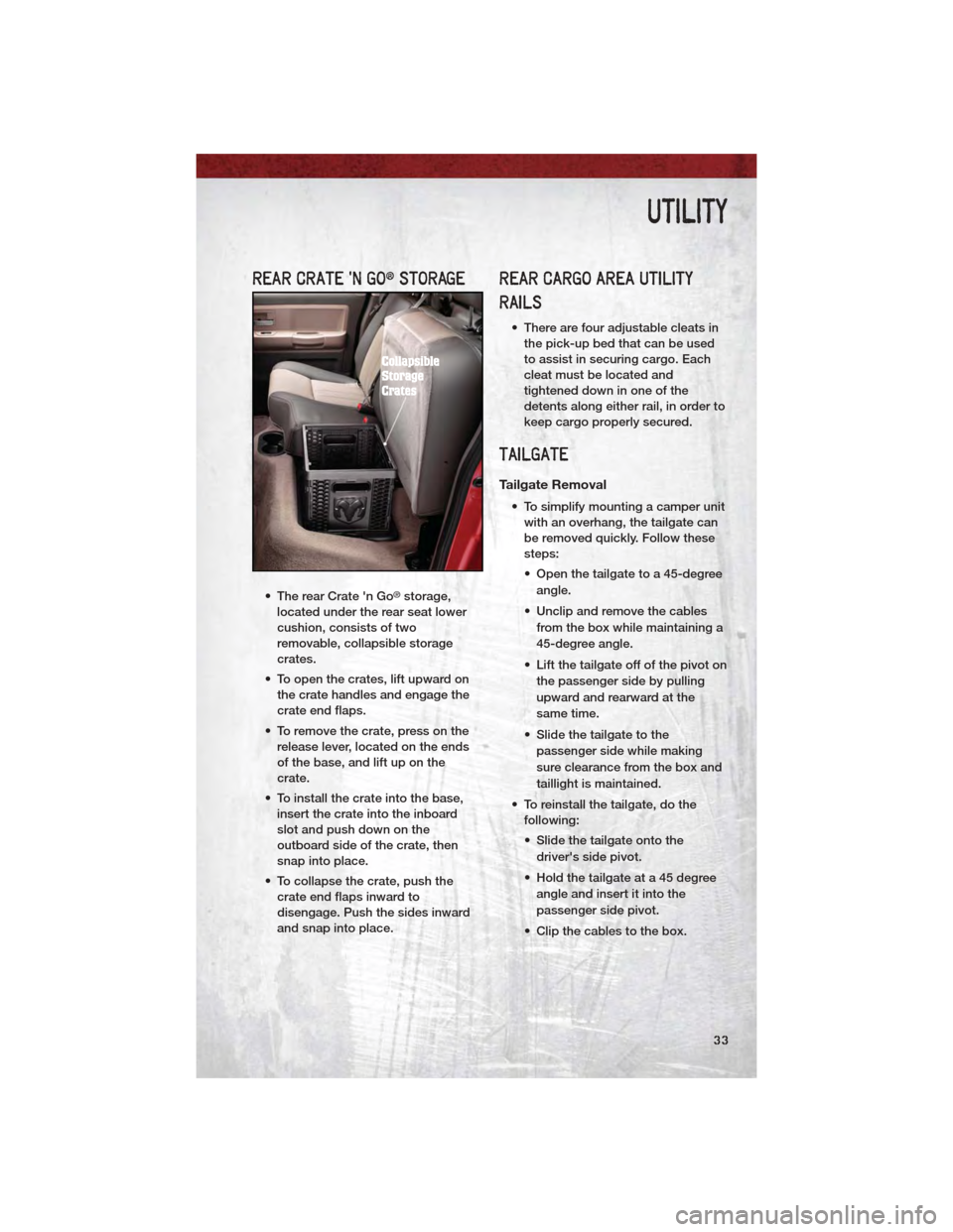
• The rear Crate 'n Go®storage,
located under the rear seat lower
cushion, consists of two
removable, collapsible storage
crates.
• To open the crates, lift upward on the crate handles and engage the
crate end flaps.
• To remove the crate, press on the release lever, located on the ends
of the base, and lift up on the
crate.
• To install the crate into the base, insert the crate into the inboard
slot and push down on the
outboard side of the crate, then
snap into place.
• To collapse the crate, push the crate end flaps inward to
disengage. Push the sides inward
and snap into place.
REAR CARGO AREA UTILITY
RAILS
• There are four adjustable cleats inthe pick-up bed that can be used
to assist in securing cargo. Each
cleat must be located and
tightened down in one of the
detents along either rail, in order to
keep cargo properly secured.
TAILGATE
Tailgate Removal
• To simplify mounting a camper unitwith an overhang, the tailgate can
be removed quickly. Follow these
steps:
• Open the tailgate to a 45-degree
angle.
• Unclip and remove the cables from the box while maintaining a
45-degree angle.
• Lift the tailgate off of the pivot on the passenger side by pulling
upward and rearward at the
same time.
• Slide the tailgate to the passenger side while making
sure clearance from the box and
taillight is maintained.
• To reinstall the tailgate, do the following:
• Slide the tailgate onto the
driver's side pivot.
• Hold the tailgate at a 45 degree angle and insert it into the
passenger side pivot.
• Clip the cables to the box.
UTILITY
33