transmission DODGE DART 2014 PF / 1.G Owner's Manual
[x] Cancel search | Manufacturer: DODGE, Model Year: 2014, Model line: DART, Model: DODGE DART 2014 PF / 1.GPages: 140, PDF Size: 4.57 MB
Page 90 of 140
• Press and hold the RIGHTarrow button for one second to access the ”Oil Life Reset”
screen.
• Press and hold the DOWN
arrow button until the screen shows 100% oil life.
• Press and release the Up arrow button to exit the EVIC screen.
NOTE:
If the indicator message illuminates when you start the vehicle, the oil change indicator
system did not reset. If necessary, repeat this procedure.
IF YOUR ENGINE OVERHEATS
• In any of the following situations, you can reduce the potential for overheating by taking the appropriate action.
• On the highways — slow down.
• In city traffic — while stopped, place the transmission in NEUTRAL, but do not increase engine idle speed.
NOTE:
There are steps that you can take to slow down an impending overheat condition:
• If your air conditioner (A/C) is on, turn it off. The A/C system adds heat to the engine cooling system and turning the A/C off can help remove this heat.
• You can also turn the temperature control to maximum heat, the mode control to floor and the blower control to high. This allows the heater core to act as a supplement to the
radiator and aids in removing heat from the engine cooling system.
CAUTION!
Vehicles with base cluster
• Driving with a hot cooling system could damage your vehicle. If the temperature gauge reads H (hot), pull over and stop the vehicle. Idle the vehicle with the air
conditioner turned off until the pointer drops back into the normal range. If the
pointer remains on H (hot), turn the engine off immediately and call for service.
Vehicles with premium cluster
• Driving with a hot cooling system could damage your vehicle. If the temperature gauge reads 240°F (116 °C) or greater pull over and stop the vehicle. Idle the vehicle
with the air conditioner turned off until the pointer drops back into the normal range
200–230°F (93–110°C). If the pointer remains at 240°F (116°C) or greater and you hear
a chime, turn the engine off immediately and call for service.
WHAT TO DO IN EMERGENCIES
88
Page 96 of 140
WARNING!
• Do not attempt to change a tire on the side of the vehicle close to moving traffic. Pullfar enough off the road to avoid the danger of being hit when operating the jack or
changing the wheel.
• Being under a jacked-up vehicle is dangerous. The vehicle could slip off the jack and
fall on you. You could be crushed. Never put any part of your body under a vehicle that
is on a jack. If you need to get under a raised vehicle, take it to an authorized service
center where it can be raised on a lift.
• Never start or run the engine while the vehicle is on a jack.
• The jack is designed to be used as a tool for changing tires only. The jack should not
be used to lift the vehicle for service purposes. The vehicle should be jacked on a firm
level surface only. Avoid ice or slippery areas.
• Carefully follow these tire changing warnings to help prevent personal injury or
damage to your vehicle:
• Always park on a firm, level surface as far from the edge of the roadway as possible
before raising the vehicle.
• Turn on the Hazard Warning flasher.
• Block the wheel diagonally opposite the wheel to be raised.
• Set the parking brake firmly and set an automatic transmission in PARK.
• Do not let anyone sit in the vehicle when it is on a jack.
• Do not get under the vehicle when it is on a jack.
• Only use the jack in the positions indicated and for lifting this vehicle during a tire
change.
• If working on or near a roadway, be extremely careful of motor traffic.
• To assure that spare tires, flat or inflated, are securely stowed, spares must be
stowed with the valve stem facing the ground.
• Raising the vehicle higher than necessary can make the vehicle less stable. It could
slip off the jack and hurt someone near it. Raise the vehicle only enough to remove
the tire.
• To avoid possible personal injury, handle the wheel covers with care to avoid contact
with any sharp edges.
•
To avoid the risk of forcing the vehicle off the jack, do not tighten the wheel nuts fully
until the vehicle has been lowered. Failure to follow this warning may result in personal
injury.
• A loose tire or jack, thrown forward in a collision or hard stop could endanger the
occupants of the vehicle. Always stow the jack parts and the spare tire in the places
provided. Have the deflated (flat) tire repaired or replaced immediately.
WHAT TO DO IN EMERGENCIES
94
Page 98 of 140
TIREFIT Usage Precautions
• Replace the TIREFIT Sealant Bottle (1) and Sealant Hose (6) prior to the expiration date(printed on the bottle label) to assure optimum operation of the system. Refer to “Sealing
a Tire with TIREFIT” section (F) “Sealant Bottle and Hose Replacement.”
• The Sealant Bottle (1) and Sealant Hose (6) are a one tire application use. After each use, always replace these components immediately at an authorized dealer.
• When the TIREFIT sealant is in a liquid form, clean water, and a damp cloth will remove the material from the vehicle or tire and wheel components. Once the sealant dries, it can
easily be peeled off and properly discarded.
• For optimum performance, make sure the valve stem on the wheel is free of debris before connecting the TIREFIT kit.
• You can use the TIREFIT air pump to inflate bicycle tires. The kit also comes with two needles, located in the Accessory Storage Compartment (on the bottom of the air pump)
for inflating sport balls, rafts, or similar inflatable items. However, use only the Air Pump
Hose (7) and make sure the Mode Select Knob (5) is in the Air Mode when inflating such
items to avoid injecting sealant into them. The TIREFIT Sealant is only intended to seal
punctures less than 1/4” (6 mm) diameter in the tread of your vehicle.
• Do not lift or carry the TIREFIT kit by the hoses.
Sealing A Tire With TIREFIT
(A) Whenever You Stop To Use TIREFIT:
1. Pull over to a safe location and turn on the vehicle’s Hazard Warning flashers.
2. Verify that the valve stem (on the wheel with the deflated tire) is in a position that is near to the ground. This will allow the TIREFIT Hoses (6) and (7) to reach the valve stem and
keep the TIREFIT kit flat on the ground. This will provide the best positioning of the kit
when injecting the sealant into the deflated tire and running the air pump. Move the
vehicle as necessary to place the valve stem in this position before proceeding.
3. Place the transmission in PARK (auto transmission) or in Gear (manual transmission) and cycle the ignition to the OFF position.
4. Set the parking brake.
(B) Setting Up To Use TIREFIT:
1. Turn the Mode Select Knob (5) to the Sealant Mode position.
2. Uncoil the Sealant Hose (6) and then remove the cap from the fitting at the end of the hose.
3. Place the TIREFIT kit flat on the ground next to the deflated tire.
4. Remove the cap from the valve stem and then screw the fitting at the end of the Sealant Hose (6) onto the valve stem.
5. Uncoil the Power Plug (8) and insert the plug into the vehicle’s 12 Volt power outlet.
6. Do not remove foreign objects (e.g., screws or nails) from the tire.
WHAT TO DO IN EMERGENCIES
96
Page 99 of 140
(C) Injecting TIREFIT Sealant Into The Deflated Tire:
Always start the engine before turning ON the TIREFIT kit.
NOTE:
Manual transmission vehicles must have the parking brake engaged and the shift lever in
NEUTRAL.
After pressing the Power Button (4), the sealant (white fluid) will flow from the Sealant Bottle
(1) through the Sealant Hose (6) and into the tire.
NOTE:
Sealant may leak out through the puncture in the tire.
If the sealant (white fluid) does not flow within0–10seconds through the Sealant
Hose (6):
1. Press the Power Button (4) to turn Off the TIREFIT kit. Disconnect the Sealant Hose (6) from the valve stem. Make sure the valve stem is free of debris. Reconnect the Sealant
Hose (6) to the valve stem. Check that the Mode Select Knob (5) is in the Sealant Mode
position and not Air Mode. Press the Power Button (4) to turn On the TIREFIT kit.
2. Connect the Power Plug (8) to a different 12 Volt power outlet in your vehicle or another vehicle, if available. Make sure the engine is running before turning ON the TIREFIT kit.
3. The Sealant Bottle (1) may be empty due to previous use. Call for assistance.
NOTE:
If the Mode Select Knob (5) is on Air Mode and the pump is operating, air will dispense from
the Air Pump Hose (7) only, not the Sealant Hose (6).
If the sealant (white fluid) does flow through the Sealant Hose (6):
1. Continue to operate the pump until sealant is no longer flowing through the hose (typically takes 30 - 70 seconds). As the sealant flows through the Sealant Hose (6), the
Pressure Gauge (3) can read as high as 70 psi (4.8 Bar). The Pressure Gauge (3) will
decrease quickly from approximately 70 psi (4.8 Bar) to the actual tire pressure when the
Sealant Bottle (1) is empty.
2. The pump will start to inject air into the tire immediately after the Sealant Bottle (1) is empty. Continue to operate the pump and inflate the tire to the pressure indicated on the
tire pressure label on the driver-side latch pillar (recommended pressure). Check the tire
pressure by looking at the Pressure Gauge (3).
If the tire does not inflate to at least 26 psi (1.8 Bar) pressure within 15 minutes:
The tire is too badly damaged. Do not attempt to drive the vehicle further. Call for assistance.
NOTE:
If the tire becomes over-inflated, press the Deflation Button to reduce the tire pressure to
the recommended inflation pressure before continuing.
WHAT TO DO IN EMERGENCIES
97
Page 103 of 140
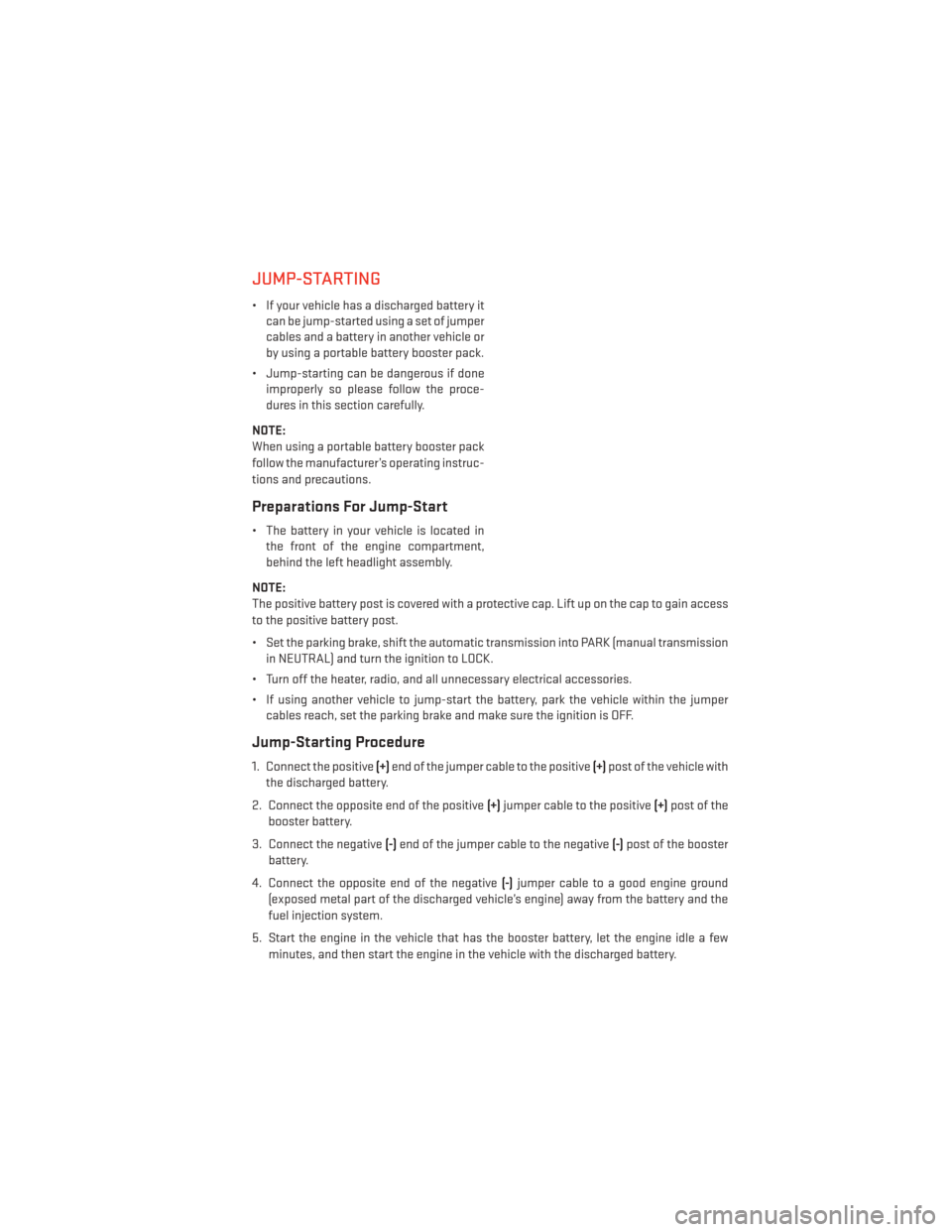
JUMP-STARTING
• If your vehicle has a discharged battery itcan be jump-started using a set of jumper
cables and a battery in another vehicle or
by using a portable battery booster pack.
• Jump-starting can be dangerous if done improperly so please follow the proce-
dures in this section carefully.
NOTE:
When using a portable battery booster pack
follow the manufacturer’s operating instruc-
tions and precautions.
Preparations For Jump-Start
• The battery in your vehicle is located in the front of the engine compartment,
behind the left headlight assembly.
NOTE:
The positive battery post is covered with a protective cap. Lift up on the cap to gain access
to the positive battery post.
• Set the parking brake, shift the automatic transmission into PARK (manual transmission in NEUTRAL) and turn the ignition to LOCK.
• Turn off the heater, radio, and all unnecessary electrical accessories.
• If using another vehicle to jump-start the battery, park the vehicle within the jumper cables reach, set the parking brake and make sure the ignition is OFF.
Jump-Starting Procedure
1. Connect the positive (+)end of the jumper cable to the positive (+)post of the vehicle with
the discharged battery.
2. Connect the opposite end of the positive (+)jumper cable to the positive (+)post of the
booster battery.
3. Connect the negative (-)end of the jumper cable to the negative (-)post of the booster
battery.
4. Connect the opposite end of the negative (-)jumper cable to a good engine ground
(exposed metal part of the discharged vehicle’s engine) away from the battery and the
fuel injection system.
5. Start the engine in the vehicle that has the booster battery, let the engine idle a few minutes, and then start the engine in the vehicle with the discharged battery.
WHAT TO DO IN EMERGENCIES
101
Page 106 of 140
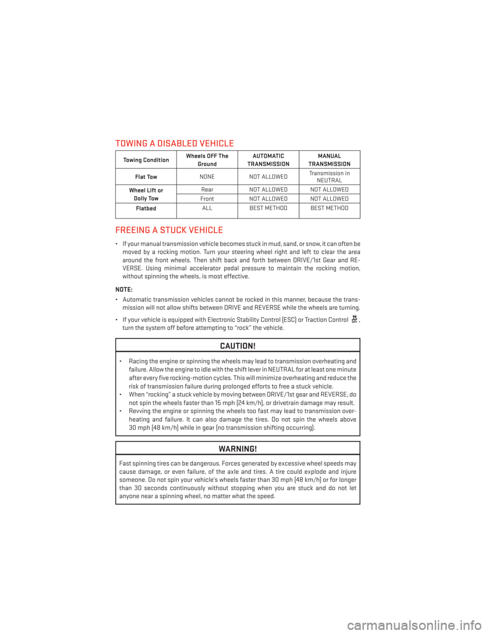
TOWING A DISABLED VEHICLE
Towing ConditionWheels OFF The
Ground AUTOMATIC
TRANSMISSION MANUAL
TRANSMISSION
Flat Tow NONE
NOT ALLOWED Transmission in
NEUTRAL
Wheel Lift or Dolly Tow Rear
NOT ALLOWED NOT ALLOWED
Front NOT ALLOWED NOT ALLOWED
Flatbed ALL
BEST METHOD BEST METHOD
FREEING A STUCK VEHICLE
• If your manual transmission vehicle becomes stuck in mud, sand, or snow, it can often be
moved by a rocking motion. Turn your steering wheel right and left to clear the area
around the front wheels. Then shift back and forth between DRIVE/1st Gear and RE-
VERSE. Using minimal accelerator pedal pressure to maintain the rocking motion,
without spinning the wheels, is most effective.
NOTE:
• Automatic transmission vehicles cannot be rocked in this manner, because the trans- mission will not allow shifts between DRIVE and REVERSE while the wheels are turning.
• If your vehicle is equipped with Electronic Stability Control (ESC) or Traction Control
,
turn the system off before attempting to “rock” the vehicle.
CAUTION!
• Racing the engine or spinning the wheels may lead to transmission overheating and
failure. Allow the engine to idle with the shift lever in NEUTRAL for at least one minute
after every five rocking-motion cycles. This will minimize overheating and reduce the
risk of transmission failure during prolonged efforts to free a stuck vehicle.
• When “rocking” a stuck vehicle by moving between DRIVE/1st gear and REVERSE, do
not spin the wheels faster than 15 mph (24 km/h), or drivetrain damage may result.
• Revving the engine or spinning the wheels too fast may lead to transmission over-
heating and failure. It can also damage the tires. Do not spin the wheels above
30 mph (48 km/h) while in gear (no transmission shifting occurring).
WARNING!
Fast spinning tires can be dangerous. Forces generated by excessive wheel speeds may
cause damage, or even failure, of the axle and tires. A tire could explode and injure
someone. Do not spin your vehicle's wheels faster than 30 mph (48 km/h) or for longer
than 30 seconds continuously without stopping when you are stuck and do not let
anyone near a spinning wheel, no matter what the speed.
WHAT TO DO IN EMERGENCIES
104
Page 114 of 140
![DODGE DART 2014 PF / 1.G Owners Manual ComponentFluid, Lubricant, or Genuine
Part Capacities
Spark Plugs 2.0L Engine We recommend you use MOPAR® Spark Plugs
(Gap 0.043 in [1.1 mm]) —
Spark Plugs 2.4L Engine We recommend you use MOPAR® DODGE DART 2014 PF / 1.G Owners Manual ComponentFluid, Lubricant, or Genuine
Part Capacities
Spark Plugs 2.0L Engine We recommend you use MOPAR® Spark Plugs
(Gap 0.043 in [1.1 mm]) —
Spark Plugs 2.4L Engine We recommend you use MOPAR®](/img/12/5599/w960_5599-113.png)
ComponentFluid, Lubricant, or Genuine
Part Capacities
Spark Plugs 2.0L Engine We recommend you use MOPAR® Spark Plugs
(Gap 0.043 in [1.1 mm]) —
Spark Plugs 2.4L Engine We recommend you use MOPAR® Spark Plugs
(Gap 0.047 in [1.2 mm]) —
Automatic Transmission –
1.4L Turbo Engine We recommend you use
MOPAR® C635 DDCT/MTX
Transmission Fluid. —
Automatic Transmission –
2.0L, 2.4L Engine We recommend you use
SK Energy ATF SP-4 Trans-
mission Fluid. —
Manual Transmission We recommend you use MOPAR® C635 DDCT/MTX
Transmission Fluid. —
Brake Master Cylinder We recommend you use MOPAR® DOT 3 SAE J1703.
If DOT 3 is not available, then
DOT 4 is acceptable. Only use
recommended brake fluids. —
CAUTION!
• Mixing of engine coolant (antifreeze) other than specified Organic Additive Technol-
ogy (OAT) engine coolant (antifreeze), may result in engine damage and may de-
crease corrosion protection. Organic Additive Technology (OAT) engine coolant is
different and should not be mixed with Hybrid Organic Additive Technology (HOAT)
engine coolant (antifreeze) or any “globally compatible” coolant (antifreeze). If a
non-OAT engine coolant (antifreeze) is introduced into the cooling system in an
emergency, the cooling system will need to be drained, flushed, and refilled with
fresh OAT coolant (conforming to MS-12106), by an authorized dealer as soon as
possible.
• Do not use water alone or alcohol-based engine coolant (antifreeze) products. Do not
use additional rust inhibitors or antirust products, as they may not be compatible
with the radiator engine coolant and may plug the radiator.
• This vehicle has not been designed for use with propylene glycol-based engine
coolant (antifreeze). Use of propylene glycol-based engine coolant (antifreeze) is not
recommended.
MAINTAINING YOUR VEHICLE
112
Page 116 of 140
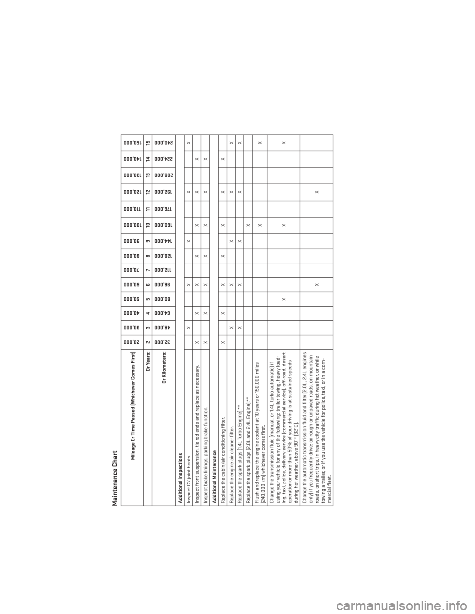
Maintenance Chart
Mileage Or Time Passed (Whichever Comes First)
20,00030,000
40,000
50,000
60,000 70,000
80,000
90,000
100,000
110,000
120,000
130,000
140,000
150,000
Or Years: 2 3 4 5 6 7 8 9 10 11 12 13 14 15
Or Kilometers:
32,000
48,000 64,000
80,000 96,000
112,000
128,000
144,000
160,000
176,000
192,000
208,000 224,000
240,000
Additional Inspections
Inspect CV joint boots. X X X X X
Inspect front suspension, tie rod ends and replace as necessary. X X X X X X X
Inspect brake linings, parking brake function. X X X X X X X
Additional Maintenance
Replace the cabin/air conditioning filter. X X X X X X X
Replace the engine air cleaner filter. X X X X X
Replace the spark plugs (1.4L Turbo Engine).** X X X X X
Replace the spark plugs (2.0L and 2.4L Engine).** X
Flush and replace the engine coolant at 10 years or 150,000 miles
(240,000 km) whichever comes first. XX
Change the transmission fluid (manual, or 1.4L turbo automatic) if
using your vehicle for any of the following: trailer towing, heavy load-
ing, taxi, police, delivery service (commercial service), off-road, desert
operation or more than 50% of your driving is at sustained speeds
during hot weather, above 90°F (32°C). XX X
Change the automatic transmission fluid and filter (2.0L, 2.4L engines
only) if you frequently drive: on rough or unpaved roads, on mountain
roads, on short trips, in heavy city traffic during hot weather, or while
towing a trailer, or if you use the vehicle for police, taxi, or in a com-
mercial fleet. XX
MAINTAINING YOUR VEHICLE
114
Page 119 of 140
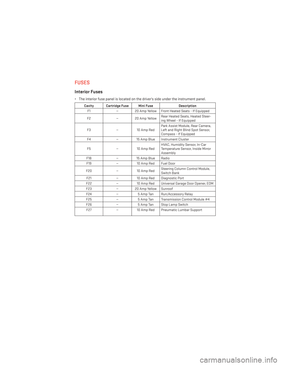
FUSES
Interior Fuses
• The interior fuse panel is located on the driver's side under the instrument panel.
Cavity Cartridge Fuse Mini FuseDescription
F1 — 20 Amp Yellow Front Heated Seats - If Equipped
F2 — 20 Amp Yellow Rear Heated Seats, Heated Steer-
ing Wheel - If Equipped
F3 — 10 Amp Red Park Assist Module, Rear Camera,
Left and Right Blind Spot Sensor,
Compass - If Equipped
F4 — 15 Amp Blue Instrument Cluster
F5 — 10 Amp Red HVAC, Humidity Sensor, In-Car
Temperature Sensor, Inside Mirror
Assembly
F18 — 15 Amp Blue Radio
F19 — 10 Amp Red Fuel Door
F20 — 10 Amp Red Steering Column Control Module,
Switch Bank
F21 — 10 Amp Red Diagnostic Port
F22 — 10 Amp Red Universal Garage Door Opener, EOM
F23 — 20 Amp Yellow Sunroof
F24 —5 Amp Tan Run/Accessory Relay
F25 —5 Amp Tan Transmission Control Module #4
F26 —5 Amp Tan Stop Lamp Switch
F27 — 10 Amp Red Pneumatic Lumbar Support
MAINTAINING YOUR VEHICLE
117
Page 120 of 140
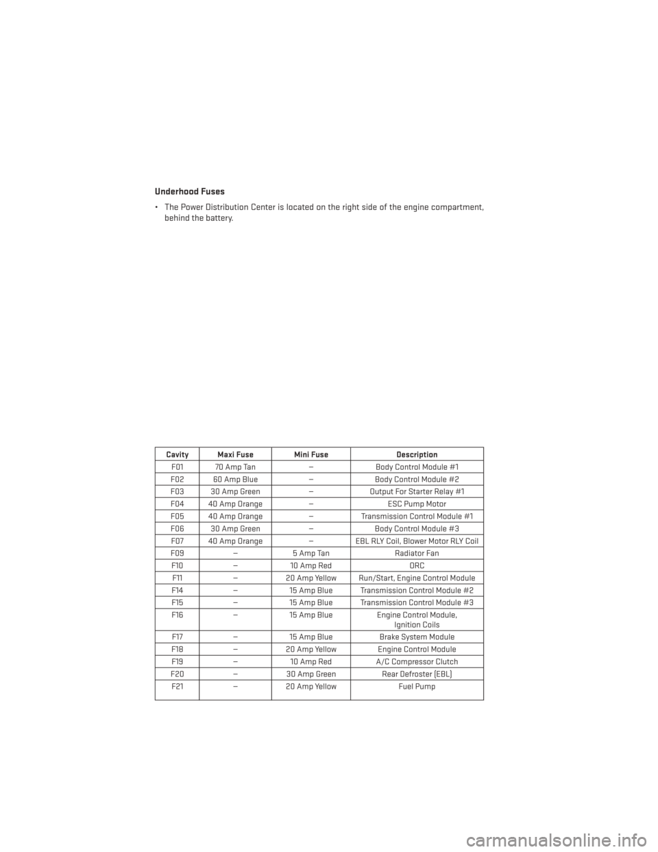
Underhood Fuses
• The Power Distribution Center is located on the right side of the engine compartment,behind the battery.
Cavity Maxi Fuse Mini Fuse Description
F01 70 Amp Tan —Body Control Module #1
F02 60 Amp Blue —Body Control Module #2
F03 30 Amp Green —Output For Starter Relay #1
F04 40 Amp Orange —ESC Pump Motor
F05 40 Amp Orange —Transmission Control Module #1
F06 30 Amp Green —Body Control Module #3
F07 40 Amp Orange — EBL RLY Coil, Blower Motor RLY Coil
F09 —5 Amp Tan Radiator Fan
F10 —10 Amp Red ORC
F11 —20 Amp Yellow Run/Start, Engine Control Module
F14 —15 Amp Blue Transmission Control Module #2
F15 —15 Amp Blue Transmission Control Module #3
F16 —15 Amp Blue Engine Control Module,
Ignition Coils
F17 —15 Amp Blue Brake System Module
F18 —20 Amp Yellow Engine Control Module
F19 —10 Amp Red A/C Compressor Clutch
F20 —30 Amp Green Rear Defroster (EBL)
F21 —20 Amp Yellow Fuel Pump
MAINTAINING YOUR VEHICLE
118