DODGE DART 2015 PF / 1.G Owners Manual
Manufacturer: DODGE, Model Year: 2015, Model line: DART, Model: DODGE DART 2015 PF / 1.GPages: 164, PDF Size: 25.19 MB
Page 91 of 164
•Pushthebuttoninthecentertoselectthenextpresetstation(radio)ortochangeCDs
if equipped with a CD Changer.
ELECTRONIC VEHICLE INFORMATION CENTER (EVIC) —
STANDARD (2 BUTTON)
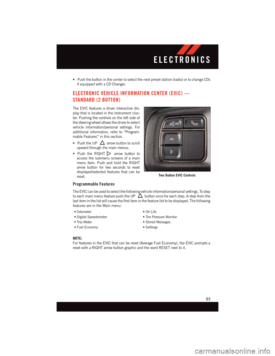
The EVIC features a driver interactive dis-
play that is located in the instrument clus-
ter. Pushing the controls on the left side of
the steering wheel allows the driver to select
vehicle information/personal settings. For
additional information, refer to “Program-
mable Features” in this section.
•PushtheUParrow button to scroll
upward through the main menus.
•PushtheRIGHTarrow button to
access the submenu screens of a main
menu item. Push and hold the RIGHT
arrow button for two seconds to reset
displayed/selected features that can be
reset.
Programmable Features
The EVIC can be used to select the following vehicle information/personal settings. To step
to each main menu feature push the UPbutton once for each step. A step from the
last item in the list will cause the first item in the feature list to be displayed. The following
features are in the Main menu:
•Odometer•OilLife
•DigitalSpeedometer•TirePressureMonitor
•TripMeter•StoredMessages
•FuelEconomy•Settings
NOTE:
For features in the EVIC that can be reset (Average Fuel Economy), the EVIC prompts a
reset with a RIGHT arrow button graphic and the word RESET next to it.
Two Button EVIC Controls
ELECTRONICS
89
Page 92 of 164
DRIVER INFORMATION DISPLAY (DID) — PREMIUM (4 BUTTON)
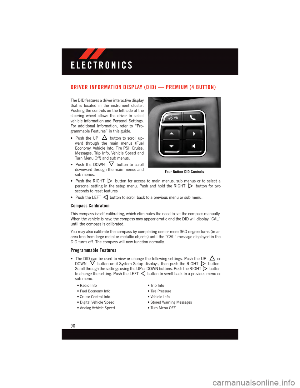
The DID features a driver interactive display
that is located in the instrument cluster.
Pushing the controls on the left side of the
steering wheel allows the driver to select
vehicle information and Personal Settings.
For additional information, refer to “Pro-
grammable Features” in this guide.
•PushtheUPbutton to scroll up-
ward through the main menus (Fuel
Economy, Vehicle Info, Tire PSI, Cruise,
Messages, Trip Info, Vehicle Speed and
Tu r n M e n u O f f ) a n d s u b m e n u s .
•PushtheDOWNbutton to scroll
downward through the main menus and
sub menus.
•PushtheRIGHTbutton for access to main menus, sub menus or to select a
personal setting in the setup menu. Push and hold the RIGHTbutton for two
seconds to reset features
•PushtheLEFTbutton to scroll back to a previous menu or sub menu.
Compass Calibration
This compass is self-calibrating, which eliminates the need to set the compass manually.
When the vehicle is new, the compass may appear erratic and the DID will display “CAL”
until the compass is calibrated.
Yo u m a y a l s o c a l i b r a t e t h e c o m p a s s b y c o m p l e t i n g o n e o r m o r e 3 6 0 d e g r e e t u r n s ( i n a n
area free from large metal or metallic objects) until the “CAL” message displayed in the
DID turns off. The compass will now function normally.
Programmable Features
•TheDIDcanbeusedtovieworchangethefollowingsettings.PushtheUPor
DOWNbutton until System Setup displays, then push the RIGHTbutton.
Scroll through the settings using the UP or DOWN buttons. Push the RIGHTbutton
to change the setting. Push the LEFTbutton to scroll back to a previous menu or
sub menu.
•RadioInfo•TripInfo
•FuelEconomyInfo•TirePressure
•CruiseControlInfo•VehicleInfo
•DigitalVehicleSpeed•StoredWarningMessages
•AnalogVehicleSpeed•TurnMenuOFF
Four Button DID Controls
ELECTRONICS
90
Page 93 of 164
DID Selectable Menu Items
The following items can be selected in the DID menu.
Full Speedometer Analog Or Digital Display
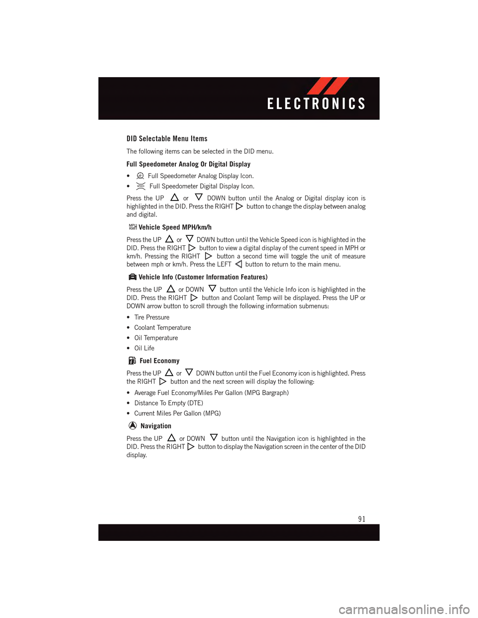
•Full Speedometer Analog Display Icon.
•Full Speedometer Digital Display Icon.
Press the UPorDOWN button until the Analog or Digital display icon is
highlighted in the DID. Press the RIGHTbutton to change the display between analog
and digital.
Vehicle Speed MPH/km/h
Press the UPorDOWN button until the Vehicle Speed icon is highlighted in the
DID. Press the RIGHTbutton to view a digital display of the current speed in MPH or
km/h. Pressing the RIGHTbutton a second time will toggle the unit of measure
between mph or km/h. Press the LEFTbutton to return to the main menu.
Vehicle Info (Customer Information Features)
Press the UPor DOWNbutton until the Vehicle Info icon is highlighted in the
DID. Press the RIGHTbutton and Coolant Temp will be displayed. Press the UP or
DOWN arrow button to scroll through the following information submenus:
•TirePressure
•CoolantTemperature
•OilTemperature
•OilLife
Fuel Economy
Press the UPorDOWN button until the Fuel Economy icon is highlighted. Press
the RIGHTbutton and the next screen will display the following:
•AverageFuelEconomy/MilesPerGallon(MPGBargraph)
•DistanceToEmpty(DTE)
•CurrentMilesPerGallon(MPG)
Navigation
Press the UPor DOWNbutton until the Navigation icon is highlighted in the
DID. Press the RIGHTbutton to display the Navigation screen in the center of the DID
display.
ELECTRONICS
91
Page 94 of 164
Trip Info
Press the UPorDOWN button until the Trip Info icon is highlighted in the DID.
Press the RIGHTbutton to display the following three trip features in the next screen:
•TripA
•TripB
•ElapsedTime
Stored Message
Press the UPorDOWN button until the Messages display icon is highlighted in
the DID. This feature shows the number of stored warning messages. Pressing the RIGHT
button will allow you to see what the stored messages are. Press the LEFTbutton
to return to the Main Menu. The inner ring of the display will illuminate grey under normal
conditions, yellow for non critical warnings, red for critical warnings and white for on
demand information.
Screen Setup
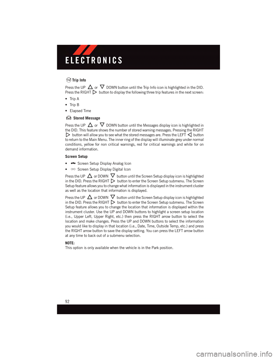
•Screen Setup Display Analog Icon
•Screen Setup Display Digital Icon
Press the UPor DOWNbutton until the Screen Setup display icon is highlighted
in the DID. Press the RIGHTbutton to enter the Screen Setup submenu. The Screen
Setup feature allows you to change what information is displayed in the instrument cluster
as well as the location that information is displayed.
Press the UPor DOWNbutton until the Screen Setup display icon is highlighted
in the DID. Press the RIGHTbutton to enter the Screen Setup submenu. The Screen
Setup feature allows you to change the location that information is displayed within the
instrument cluster. Use the UP and DOWN buttons to highlight a screen setup location
(i.e., Upper Left, Upper Right, etc.) then press the RIGHT arrow button to select the
location and make changes. Press the UP and DOWN buttons to select the information
you would like to display in that location (i.e., Date, Time, Outside Temp, etc.) and press
the RIGHT arrow button to save the display setting. You can press the LEFT arrow button
at any time to back out of a submenu selection.
NOTE:
This option is only available when the vehicle is in the Park position.
ELECTRONICS
92
Page 95 of 164
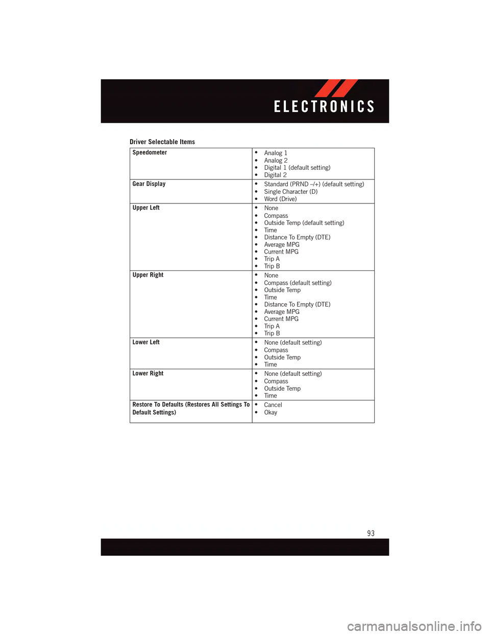
Driver Selectable Items
Speedometer•Analog 1•Analog2•Digital1(defaultsetting)•Digital2
Gear Display•Standard (PRND –/+) (default setting)•SingleCharacter(D)•Word(Drive)
Upper Left•None•Compass•OutsideTemp(defaultsetting)•Time•DistanceToEmpty(DTE)•AverageMPG•CurrentMPG•TripA•TripB
Upper Right•None•Compass(defaultsetting)•OutsideTemp•Time•DistanceToEmpty(DTE)•AverageMPG•CurrentMPG•TripA•TripB
Lower Left•None (default setting)•Compass•OutsideTemp•Time
Lower Right•None (default setting)•Compass•OutsideTemp•Time
Restore To Defaults (Restores All Settings ToDefault Settings)•Cancel•Okay
ELECTRONICS
93
Page 96 of 164
Uconnect® 8.4 CUSTOMER PROGRAMMABLE FEATURES
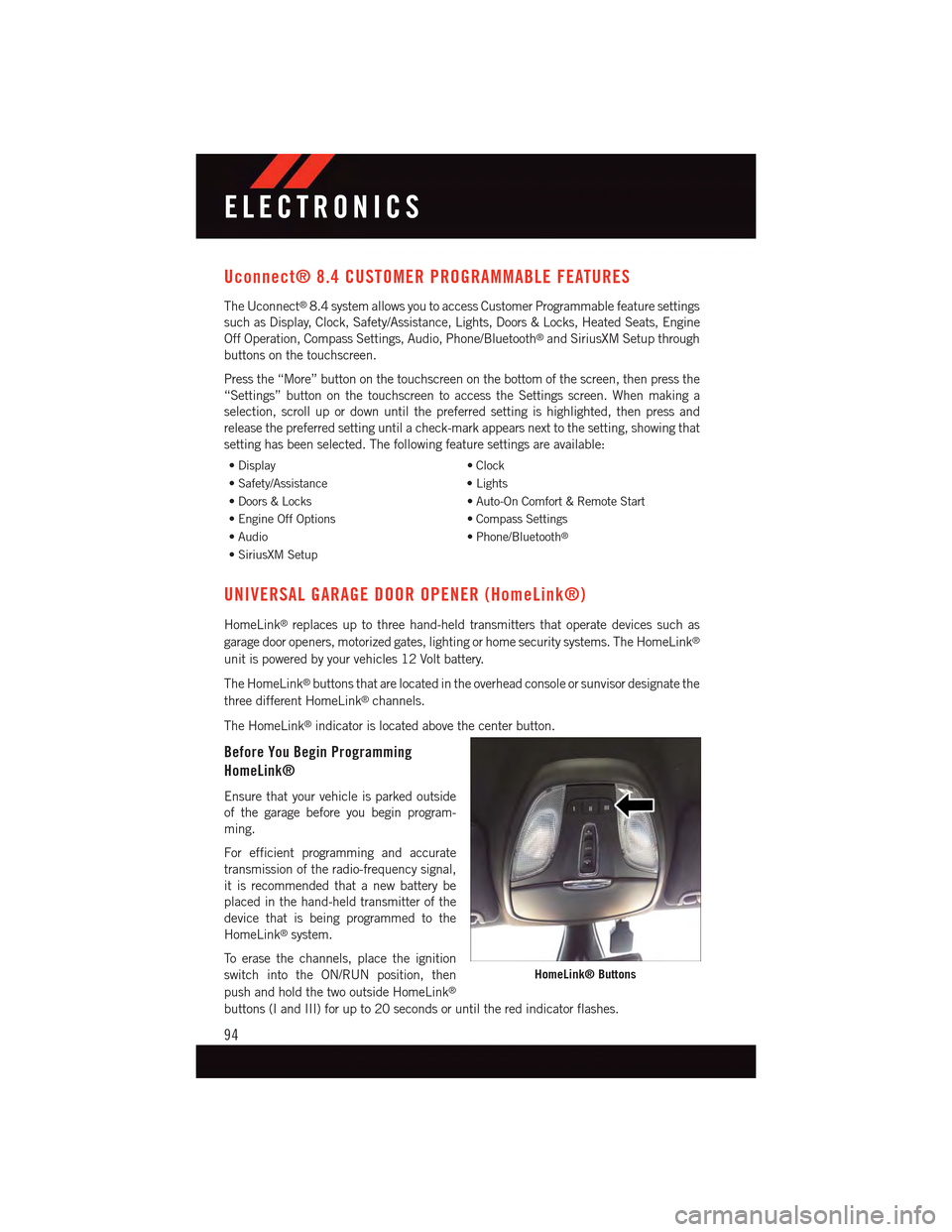
The Uconnect®8.4 system allows you to access Customer Programmable feature settings
such as Display, Clock, Safety/Assistance, Lights, Doors & Locks, Heated Seats, Engine
Off Operation, Compass Settings, Audio, Phone/Bluetooth®and SiriusXM Setup through
buttons on the touchscreen.
Press the “More” button on the touchscreen on the bottom of the screen, then press the
“Settings” button on the touchscreen to access the Settings screen. When making a
selection, scroll up or down until the preferred setting is highlighted, then press and
release the preferred setting until a check-mark appears next to the setting, showing that
setting has been selected. The following feature settings are available:
•Display•Clock
•Safety/Assistance•Lights
•Doors&Locks•Auto-OnComfort&RemoteStart
•EngineOffOptions•CompassSettings
•Audio•Phone/Bluetooth®
•SiriusXMSetup
UNIVERSAL GARAGE DOOR OPENER (HomeLink®)
HomeLink®replaces up to three hand-held transmitters that operate devices such as
garage door openers, motorized gates, lighting or home security systems. The HomeLink®
unit is powered by your vehicles 12 Volt battery.
The HomeLink®buttons that are located in the overhead console or sunvisor designate the
three different HomeLink®channels.
The HomeLink®indicator is located above the center button.
Before You Begin Programming
HomeLink®
Ensure that your vehicle is parked outside
of the garage before you begin program-
ming.
For efficient programming and accurate
transmission of the radio-frequency signal,
it is recommended that a new battery be
placed in the hand-held transmitter of the
device that is being programmed to the
HomeLink®system.
To e r a s e t h e c h a n n e l s , p l a c e t h e i g n i t i o n
switch into the ON/RUN position, then
push and hold the two outside HomeLink®
buttons (I and III) for up to 20 seconds or until the red indicator flashes.
HomeLink® Buttons
ELECTRONICS
94
Page 97 of 164
NOTE:
Erasing all channels should only be performed when programming HomeLink®for the first
time. Do not erase channels when programming additional buttons.
If you have any problems, or require assistance, please call toll-free 1-800-355-3515 or,
on the Internet at HomeLink.com for information or assistance.
Programming A Rolling Code
For programming Garage Door Openers that were manufactured after 1995. These Garage
Door Openers can be identified by the LEARN or TRAIN button located where the hanging
antenna is attached to the Garage Door Opener. It is NOT the button that is normally used
to open and close the door. The name and color of the button may vary by manufacturer.
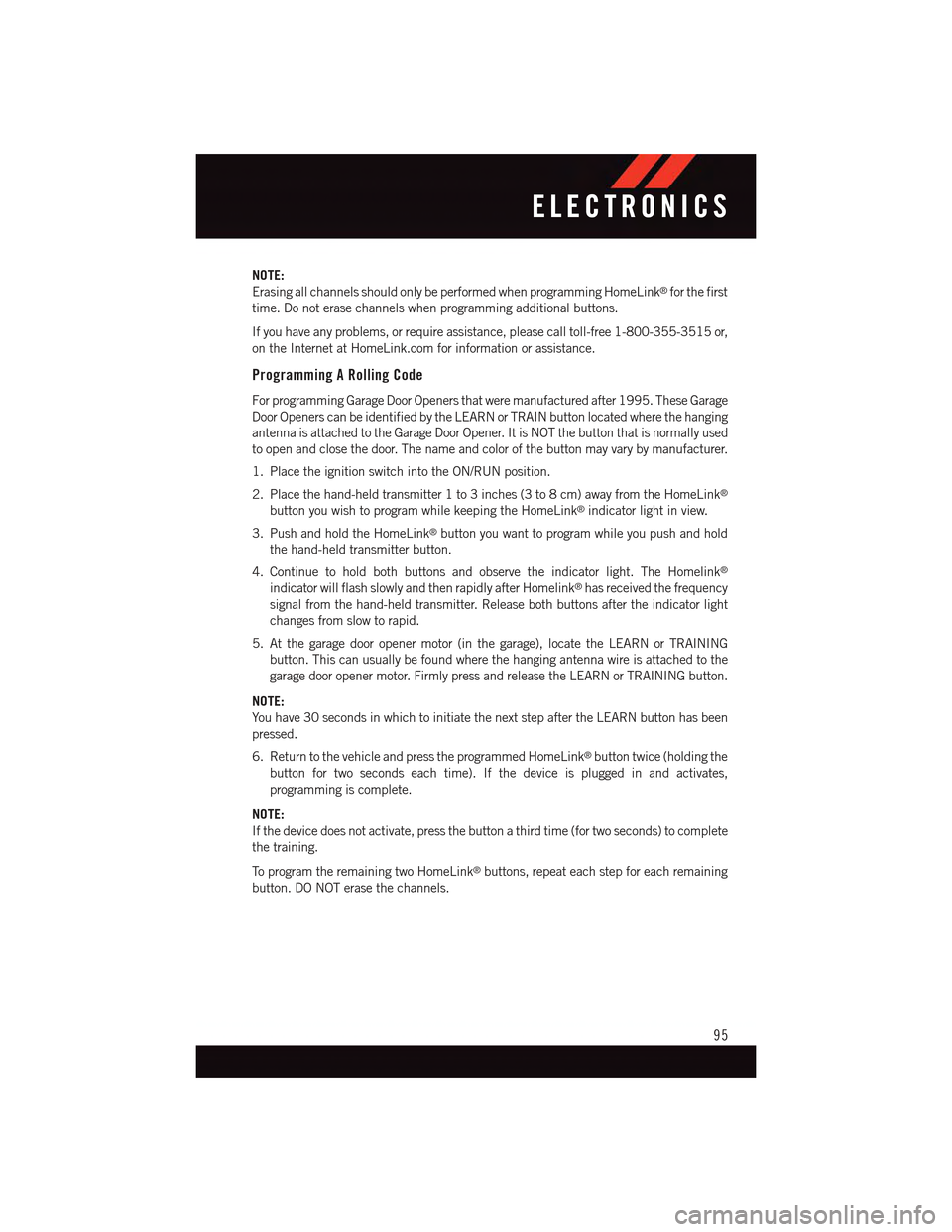
1. Place the ignition switch into the ON/RUN position.
2. Place the hand-held transmitter 1 to 3 inches (3 to 8 cm) away from the HomeLink®
button you wish to program while keeping the HomeLink®indicator light in view.
3. Push and hold the HomeLink®button you want to program while you push and hold
the hand-held transmitter button.
4. Continue to hold both buttons and observe the indicator light. The Homelink®
indicator will flash slowly and then rapidly after Homelink®has received the frequency
signal from the hand-held transmitter. Release both buttons after the indicator light
changes from slow to rapid.
5. At the garage door opener motor (in the garage), locate the LEARN or TRAINING
button. This can usually be found where the hanging antenna wire is attached to the
garage door opener motor. Firmly press and release the LEARN or TRAINING button.
NOTE:
Yo u h a v e 3 0 s e c o n d s i n w h i c h t o i n i t i a t e t h e n e x t s t e p a f t e r t h e L E A R N b u t t o n h a s b e e n
pressed.
6. Return to the vehicle and press the programmed HomeLink®button twice (holding the
button for two seconds each time). If the device is plugged in and activates,
programming is complete.
NOTE:
If the device does not activate, press the button a third time (for two seconds) to complete
the training.
To p r o g r a m t h e r e m a i n i n g t w o H o m e L i n k®buttons, repeat each step for each remaining
button. DO NOT erase the channels.
ELECTRONICS
95
Page 98 of 164
Programming A Non-Rolling Code
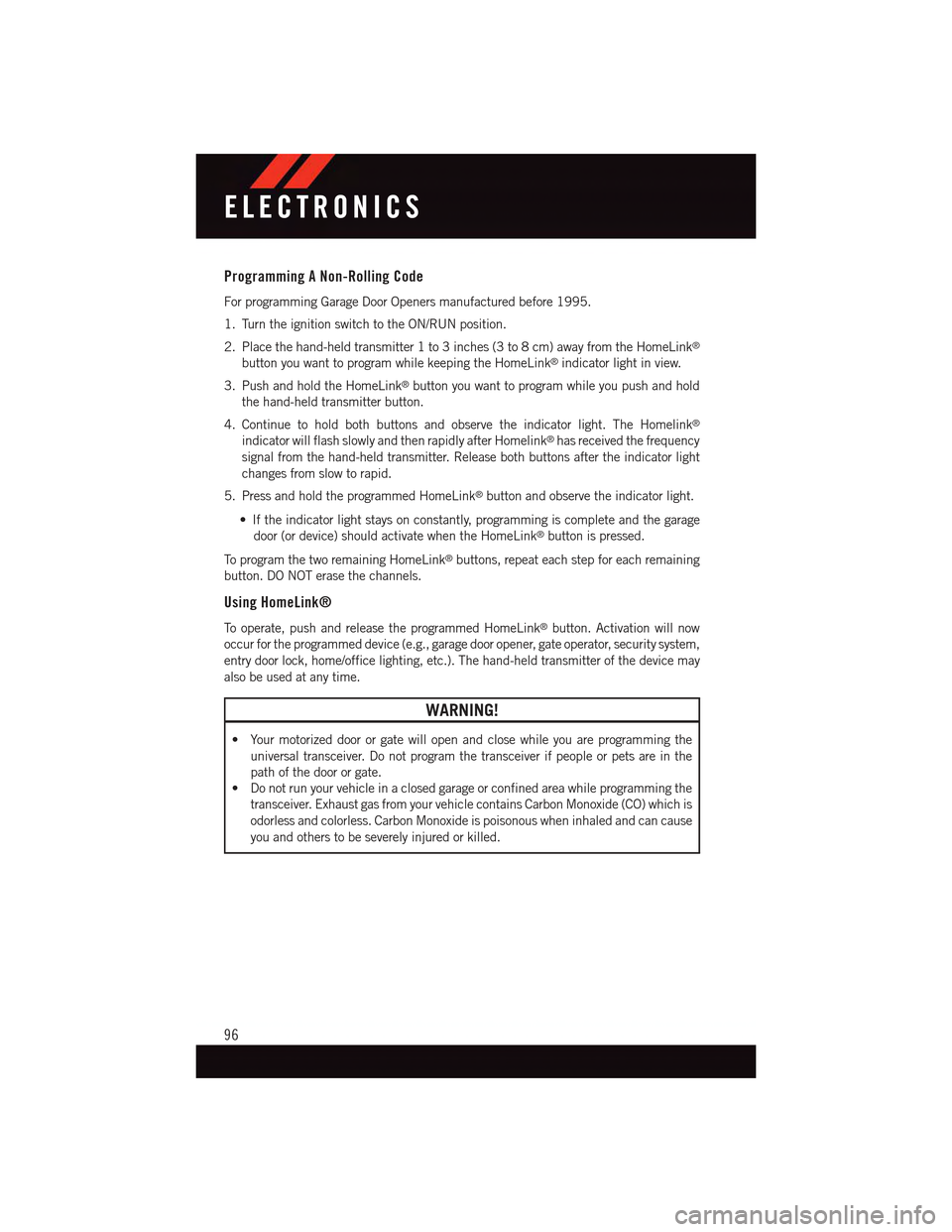
For programming Garage Door Openers manufactured before 1995.
1. Turn the ignition switch to the ON/RUN position.
2. Place the hand-held transmitter 1 to 3 inches (3 to 8 cm) away from the HomeLink®
button you want to program while keeping the HomeLink®indicator light in view.
3. Push and hold the HomeLink®button you want to program while you push and hold
the hand-held transmitter button.
4. Continue to hold both buttons and observe the indicator light. The Homelink®
indicator will flash slowly and then rapidly after Homelink®has received the frequency
signal from the hand-held transmitter. Release both buttons after the indicator light
changes from slow to rapid.
5. Press and hold the programmed HomeLink®button and observe the indicator light.
•Iftheindicatorlightstaysonconstantly,programmingiscompleteandthegarage
door (or device) should activate when the HomeLink®button is pressed.
To p r o g r a m t h e t w o r e m a i n i n g H o m e L i n k®buttons, repeat each step for each remaining
button. DO NOT erase the channels.
Using HomeLink®
To o p e r a t e , p u s h a n d r e l e a s e t h e p r o g r a m m e d H o m e L i n k®button. Activation will now
occur for the programmed device (e.g., garage door opener, gate operator, security system,
entry door lock, home/office lighting, etc.). The hand-held transmitter of the device may
also be used at any time.
WARNING!
•Yourmotorizeddoororgatewillopenandclosewhileyouareprogrammingthe
universal transceiver. Do not program the transceiver if people or pets are in the
path of the door or gate.
•Donotrunyourvehicleinaclosedgarageorconfinedareawhileprogrammingthe
transceiver. Exhaust gas from your vehicle contains Carbon Monoxide (CO) which is
odorless and colorless. Carbon Monoxide is poisonous when inhaled and can cause
you and others to be severely injured or killed.
ELECTRONICS
96
Page 99 of 164
POWER OUTLET
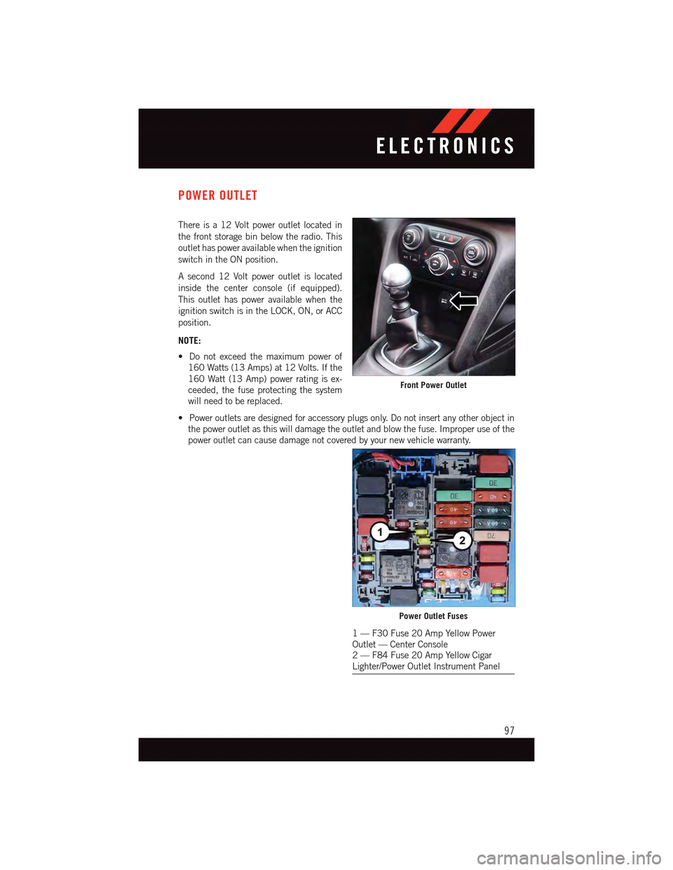
There is a 12 Volt power outlet located in
the front storage bin below the radio. This
outlet has power available when the ignition
switch in the ON position.
Asecond12Voltpoweroutletislocated
inside the center console (if equipped).
This outlet has power available when the
ignition switch is in the LOCK, ON, or ACC
position.
NOTE:
•Donotexceedthemaximumpowerof
160 Watts (13 Amps) at 12 Volts. If the
160 Watt (13 Amp) power rating is ex-
ceeded, the fuse protecting the system
will need to be replaced.
•Poweroutletsaredesignedforaccessoryplugsonly.Donotinsertanyotherobjectin
the power outlet as this will damage the outlet and blow the fuse. Improper use of the
power outlet can cause damage not covered by your new vehicle warranty.
Front Power Outlet
Power Outlet Fuses
1—F30Fuse20AmpYellowPowerOutlet — Center Console2—F84Fuse20AmpYellowCigarLighter/Power Outlet Instrument Panel
ELECTRONICS
97
Page 100 of 164
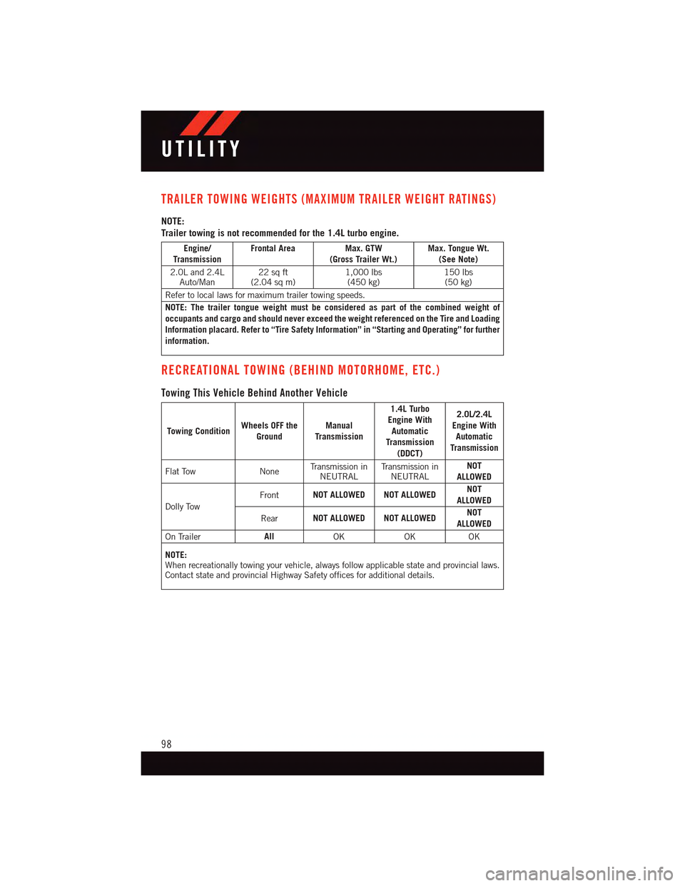
TRAILER TOWING WEIGHTS (MAXIMUM TRAILER WEIGHT RATINGS)
NOTE:
Trailer towing is not recommended for the 1.4L turbo engine.
Engine/TransmissionFrontal Area Max. GTW(Gross Trailer Wt.)Max. Tongue Wt.(See Note)
2.0L and 2.4LAuto/Man22 sq ft(2.04 sq m)1,000 lbs(450 kg)150 lbs(50 kg)
Refer to local laws for maximum trailer towing speeds.
NOTE: The trailer tongue weight must be considered as part of the combined weight ofoccupants and cargo and should never exceed the weight referenced on the Tire and LoadingInformation placard. Refer to “Tire Safety Information” in “Starting and Operating” for furtherinformation.
RECREATIONAL TOWING (BEHIND MOTORHOME, ETC.)
Towing This Vehicle Behind Another Vehicle
Towing ConditionWheels OFF theGroundManualTransmission
1.4L TurboEngine WithAutomaticTransmission(DDCT)
2.0L/2.4LEngine WithAutomaticTransmission
Flat Tow NoneTr a n s m i s s i o n i nNEUTRALTr a n s m i s s i o n i nNEUTRALNOTALLOWED
Dolly Tow
FrontNOT ALLOWED NOT ALLOWEDNOTALLOWED
RearNOT ALLOWED NOT ALLOWEDNOTALLOWED
On TrailerAllOKOKOK
NOTE:When recreationally towing your vehicle, always follow applicable state and provincial laws.Contact state and provincial Highway Safety offices for additional details.
UTILITY
98