DODGE DURANGO 1998 1.G Workshop Manual
Manufacturer: DODGE, Model Year: 1998, Model line: DURANGO, Model: DODGE DURANGO 1998 1.GPages: 193, PDF Size: 5.65 MB
Page 131 of 193
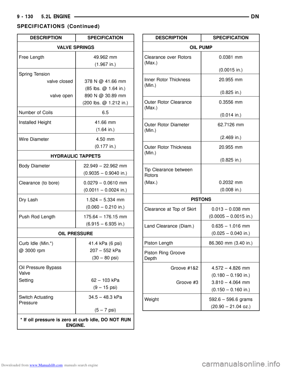
Downloaded from www.Manualslib.com manuals search engine DESCRIPTION SPECIFICATION
VALVE SPRINGS
Free Length 49.962 mm
(1.967 in.)
Spring Tension
valve closed 378 N @ 41.66 mm
(85 lbs. @ 1.64 in.)
valve open 890 N @ 30.89 mm
(200 lbs. @ 1.212 in.)
Number of Coils 6.5
Installed Height 41.66 mm
(1.64 in.)
Wire Diameter 4.50 mm
(0.177 in.)
HYDRAULIC TAPPETS
Body Diameter 22.949 ± 22.962 mm
(0.9035 ± 0.9040 in.)
Clearance (to bore) 0.0279 ± 0.0610 mm
(0.0011 ± 0.0024 in.)
Dry Lash 1.524 ± 5.334 mm
(0.060 ± 0.210 in.)
Push Rod Length 175.64 ± 176.15 mm
(6.915 ± 6.935 in.)
OIL PRESSURE
Curb Idle (Min.*) 41.4 kPa (6 psi)
@ 3000 rpm 207 ± 552 kPa
(30 ± 80 psi)
Oil Pressure Bypass
Valve
Setting 62 ± 103 kPa
(9 ± 15 psi)
Switch Actuating
Pressure34.5 ± 48.3 kPa
(5 ± 7 psi)
* If oil pressure is zero at curb idle, DO NOT RUN
ENGINE.DESCRIPTION SPECIFICATION
OIL PUMP
Clearance over Rotors
(Max.)0.0381 mm
(0.0015 in.)
Inner Rotor Thickness
(Min.)20.955 mm
(0.825 in.)
Outer Rotor Clearance
(Max.)0.3556 mm
(0.014 in.)
Outer Rotor Diameter
(Min.)62.7126 mm
(2.469 in.)
Outer Rotor Thickness
(Min.)20.955 mm
(0.825 in.)
Tip Clearance between
Rotors
(Max.) 0.2032 mm
(0.008 in.)
PISTONS
Clearance at Top of Skirt 0.013 ± 0.038 mm
(0.0005 ± 0.0015 in.)
Land Clearance (Diam.) 0.635 ± 1.016 mm
(0.025 ± 0.040 in.)
Piston Length 86.360 mm (3.40 in.)
Piston Ring Groove
Depth
Groove #1&2 4.572 ± 4.826 mm
(0.180 ± 0.190 in.)
Groove #3 3.810 ± 4.064 mm
(0.150 ± 0.160 in.)
Weight 592.6 ± 596.6 grams
(20.90 ± 21.04 oz.)
9 - 130 5.2L ENGINEDN
SPECIFICATIONS (Continued)
Page 132 of 193
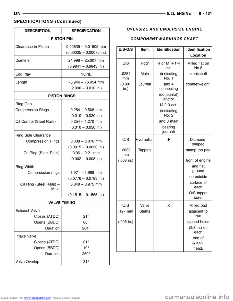
Downloaded from www.Manualslib.com manuals search engine DESCRIPTION SPECIFICATION
PISTON PIN
Clearance in Piston 0.00635 ± 0.01905 mm
(0.00025 ± 0.00075 in.)
Diameter 24.996 ± 25.001 mm
(0.9841 ± 0.9843 in.)
End Play NONE
Length 75.946 ± 76.454 mm
(2.990 ± 3.010 in.)
PISTON RINGS
Ring Gap
Compression Rings 0.254 ± 0.508 mm
(0.010 ± 0.020 in.)
Oil Control (Steel Rails) 0.254 ± 1.270 mm
(0.010 ± 0.050 in.)
Ring Side Clearance
Compression Rings 0.038 ± 0.076 mm
(0.0015 ± 0.0030 in.)
Oil Ring (Steel Rails) 0.06 ± 0.21 mm
(0.002 ± 0.008 in.)
Ring Width
Compression rings 1.971 ± 1.989 mm
(0.0776 ± 0.0783 in.)
Oil Ring (Steel Rails) ±
Max.3.848 ± 3.975 mm
(0.1515 ± 0.1565 in.)
VALVE TIMING
Exhaust Valve
Closes (ATDC) 21É
Opens (BBDC) 60É
Duration 264É
Intake Valve
Closes (ATDC) 61É
Opens (BBDC) 10É
Duration 250É
Valve Overlap 31ÉOVERSIZE AND UNDERSIZE ENGINE
COMPONENT MARKINGS CHART
U/S-O/S Item Identification Identification
Location
U/S Rod/ R or M R-1-4
ect.Milled flat on
No.8
.0254
mmMain (indicating
No. 1crankshaft
(0.001
in.)Journal and 4
connectingcounterweight.
rod journal)
and/or
M-2-3 ect.
(indicating
No. 2
and 3 main
bearing
journal)
O/S HydrauliclDiamond-
shaped
.2032
mmTappets stamp top pad
-
(.008 in.) front of engine
and flat
ground
on outside
surface of
each
O/S tappet
bore.
O/S Valve X Milled pad
.127 mm Stems adjacent to
two
(.005 in.) tapped holes
(3/8 in.) on
each
end of
cylinder
head.
DN5.2L ENGINE 9 - 131
SPECIFICATIONS (Continued)
Page 133 of 193
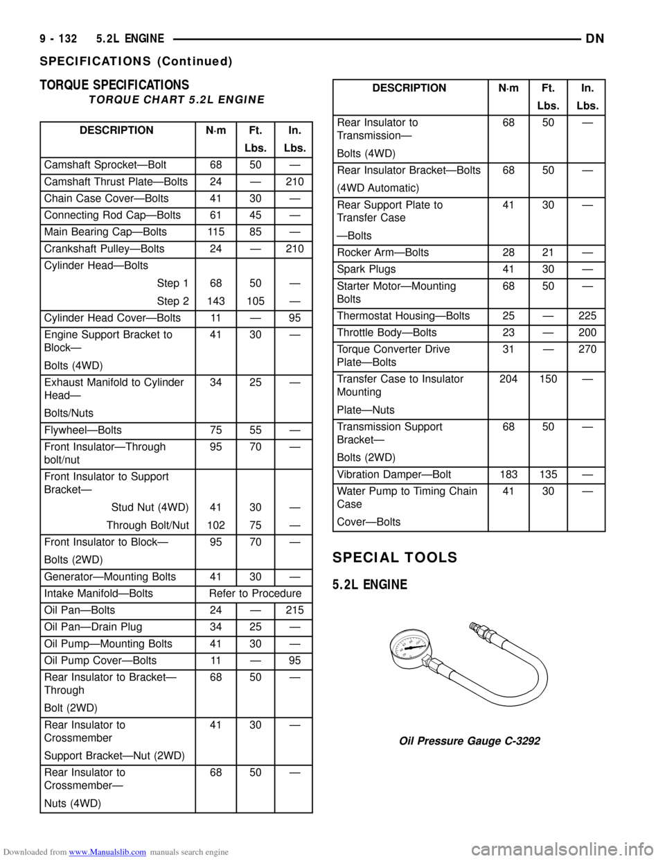
Downloaded from www.Manualslib.com manuals search engine TORQUE SPECIFICATIONS
TORQUE CHART 5.2L ENGINE
DESCRIPTION N´m Ft. In.
Lbs. Lbs.
Camshaft SprocketÐBolt 68 50 Ð
Camshaft Thrust PlateÐBolts 24 Ð 210
Chain Case CoverÐBolts 41 30 Ð
Connecting Rod CapÐBolts 61 45 Ð
Main Bearing CapÐBolts 115 85 Ð
Crankshaft PulleyÐBolts 24 Ð 210
Cylinder HeadÐBolts
Step 1 68 50 Ð
Step 2 143 105 Ð
Cylinder Head CoverÐBolts 11 Ð 95
Engine Support Bracket to
BlockÐ41 30 Ð
Bolts (4WD)
Exhaust Manifold to Cylinder
HeadÐ34 25 Ð
Bolts/Nuts
FlywheelÐBolts 75 55 Ð
Front InsulatorÐThrough
bolt/nut95 70 Ð
Front Insulator to Support
BracketÐ
Stud Nut (4WD) 41 30 Ð
Through Bolt/Nut 102 75 Ð
Front Insulator to BlockÐ 95 70 Ð
Bolts (2WD)
GeneratorÐMounting Bolts 41 30 Ð
Intake ManifoldÐBolts Refer to Procedure
Oil PanÐBolts 24 Ð 215
Oil PanÐDrain Plug 34 25 Ð
Oil PumpÐMounting Bolts 41 30 Ð
Oil Pump CoverÐBolts 11 Ð 95
Rear Insulator to BracketÐ
Through68 50 Ð
Bolt (2WD)
Rear Insulator to
Crossmember41 30 Ð
Support BracketÐNut (2WD)
Rear Insulator to
CrossmemberÐ68 50 Ð
Nuts (4WD)
DESCRIPTION N´m Ft. In.
Lbs. Lbs.
Rear Insulator to
TransmissionÐ68 50 Ð
Bolts (4WD)
Rear Insulator BracketÐBolts 68 50 Ð
(4WD Automatic)
Rear Support Plate to
Transfer Case41 30 Ð
ÐBolts
Rocker ArmÐBolts 28 21 Ð
Spark Plugs 41 30 Ð
Starter MotorÐMounting
Bolts68 50 Ð
Thermostat HousingÐBolts 25 Ð 225
Throttle BodyÐBolts 23 Ð 200
Torque Converter Drive
PlateÐBolts31 Ð 270
Transfer Case to Insulator
Mounting204 150 Ð
PlateÐNuts
Transmission Support
BracketÐ68 50 Ð
Bolts (2WD)
Vibration DamperÐBolt 183 135 Ð
Water Pump to Timing Chain
Case41 30 Ð
CoverÐBolts
SPECIAL TOOLS
5.2L ENGINE
Oil Pressure Gauge C-3292
9 - 132 5.2L ENGINEDN
SPECIFICATIONS (Continued)
Page 134 of 193
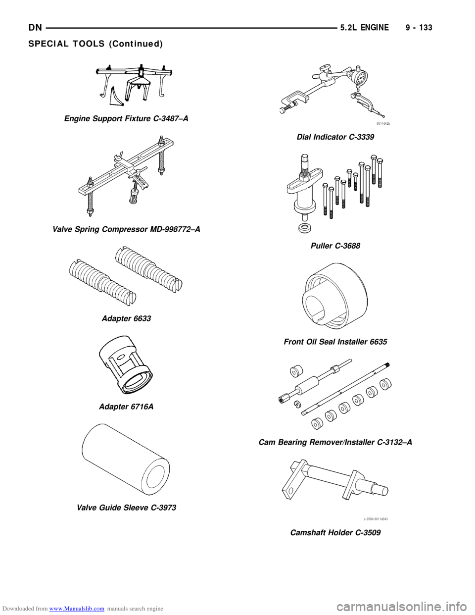
Downloaded from www.Manualslib.com manuals search engine Engine Support Fixture C-3487±A
Valve Spring Compressor MD-998772±A
Adapter 6633
Adapter 6716A
Valve Guide Sleeve C-3973
Dial Indicator C-3339
Puller C-3688
Front Oil Seal Installer 6635
Cam Bearing Remover/Installer C-3132±A
Camshaft Holder C-3509
DN5.2L ENGINE 9 - 133
SPECIAL TOOLS (Continued)
Page 135 of 193
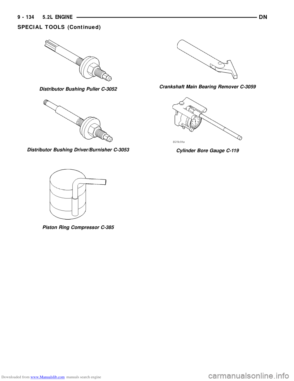
Downloaded from www.Manualslib.com manuals search engine Distributor Bushing Puller C-3052
Distributor Bushing Driver/Burnisher C-3053
Piston Ring Compressor C-385
Crankshaft Main Bearing Remover C-3059
Cylinder Bore Gauge C-119
9 - 134 5.2L ENGINEDN
SPECIAL TOOLS (Continued)
Page 136 of 193
Downloaded from www.Manualslib.com manuals search engine 5.9L ENGINE
TABLE OF CONTENTS
page page
DESCRIPTION AND OPERATION
ENGINE...............................136
ENGINE LUBRICATION SYSTEM............136
EXHAUST MANIFOLD....................139
INTAKE MANIFOLD......................139
CYLINDER HEAD COVER GASKET..........140
CYLINDER HEAD........................140
VALVES AND VALVE SPRINGS.............140
ENGINE OIL PAN........................140
CRANKSHAFT OIL SEALS.................140
PISTON AND CONNECTING ROD...........140
CRANKSHAFT MAIN BEARINGS............141
CRANKSHAFT..........................141
DIAGNOSIS AND TESTING
ENGINE DIAGNOSISÐINTRODUCTION.......141
SERVICE DIAGNOSISÐGASOLINE ENGINES . . 142
INTAKE MANIFOLD LEAKAGE DIAGNOSIS....145
CYLINDER COMPRESSION PRESSURE TEST . 145
CYLINDER HEAD GASKET FAILURE
DIAGNOSIS...........................146
CYLINDER COMBUSTION PRESSURE
LEAKAGE TEST.......................146
INSPECTION (ENGINE OIL LEAKS IN
GENERAL)...........................147
REAR SEAL AREA LEAKSÐINSPECTION.....147
HYDRAULIC TAPPETS....................148
ENGINE OIL PRESSURE..................148
SERVICE PROCEDURES
FORM-IN-PLACE GASKETS................149
ENGINE PERFORMANCE.................149
ENGINE OIL............................150
REPAIR DAMAGED OR WORN THREADS.....151
CYLINDER BOREÐHONING...............152
HYDROSTATIC LOCK.....................152
VALVE TIMING..........................153
VALVE SERVICE........................153
MEASURING TIMING CHAIN STRETCH.......155
PISTONSÐFITTING......................156
PISTON RINGSÐFITTING.................156
CONNECTING ROD BEARINGSÐFITTING.....157
CRANKSHAFT MAIN BEARINGSÐFITTING....157
REMOVAL AND INSTALLATION
ENGINE FRONT MOUNTS.................158ENGINE REAR SUPPORT.................160
ENGINE ASSEMBLY......................161
INTAKE MANIFOLD......................163
EXHAUST MANIFOLD....................165
CYLINDER HEAD COVER.................165
ROCKER ARMS AND PUSH RODS..........166
VALVE SPRING AND STEM SEAL
REPLACEMENT-IN VEHICLE.............166
CYLINDER HEAD........................167
VALVES AND VALVE SPRINGS.............167
HYDRAULIC TAPPETS....................168
VIBRATION DAMPER.....................168
TIMING CHAIN COVER...................169
TIMING CHAIN..........................170
CAMSHAFT............................170
CAMSHAFT BEARINGS...................172
DISTRIBUTOR DRIVE SHAFT BUSHING......172
CRANKSHAFT MAIN BEARINGS............174
OILPAN...............................174
PISTON AND CONNECTING ROD ASSEMBLY . . 175
CRANKSHAFT..........................176
OIL PUMP.............................177
CRANKSHAFT OIL SEALÐFRONT...........178
CRANKSHAFT OIL SEALSÐREAR...........179
ENGINE CORE OIL AND CAMSHAFT PLUGS . . 180
DISASSEMBLY AND ASSEMBLY
OIL PUMP.............................181
CLEANING AND INSPECTION
CYLINDER HEAD COVER.................182
CYLINDER HEAD ASSEMBLY..............182
PISTON AND CONNECTING ROD ASSEMBLY . . 182
OILPAN...............................182
OIL PUMP.............................182
CYLINDER BLOCK.......................185
INTAKE MANIFOLD......................185
EXHAUST MANIFOLD....................185
SPECIFICATIONS
5.9L ENGINE SPECIFICATIONS.............185
SPECIFICATIONS........................189
SPECIAL TOOLS
5.9L ENGINE...........................189
DN5.9L ENGINE 9 - 135
Page 137 of 193
Downloaded from www.Manualslib.com manuals search engine DESCRIPTION AND OPERATION
ENGINE
DESCRIPTION
The 5.9 Liter (360 CID) eight-cylinder engine is a
V-Type lightweight, single cam, overhead valve
engine with hydraulic roller tappets. This engine is
designed for unleaded fuel.
The engine lubrication system consists of a rotor
type oil pump and a full flow oil filter.
The cylinders are numbered from front to rear; 1,
3, 5, 7 on the left bank and 2, 4, 6, 8 on the right
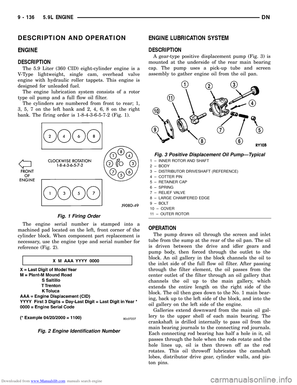
bank. The firing order is 1-8-4-3-6-5-7-2 (Fig. 1).
The engine serial number is stamped into a
machined pad located on the left, front corner of the
cylinder block. When component part replacement is
necessary, use the engine type and serial number for
reference (Fig. 2).
ENGINE LUBRICATION SYSTEM
DESCRIPTION
A gear-type positive displacement pump (Fig. 3) is
mounted at the underside of the rear main bearing
cap. The pump uses a pick-up tube and screen
assembly to gather engine oil from the oil pan.
OPERATION
The pump draws oil through the screen and inlet
tube from the sump at the rear of the oil pan. The oil
is driven between the drive and idler gears and
pump body, then forced through the outlet to the
block. An oil gallery in the block channels the oil to
the inlet side of the full flow oil filter. After passing
through the filter element, the oil passes from the
center outlet of the filter through an oil gallery that
channels the oil up to the main gallery, which
extends the entire length on the right side of the
block. The oil then goes down to the No. 1 main bear-
ing, back up to the left side of the block, and into the
oil gallery on the left side of the engine.
Galleries extend downward from the main oil gal-
lery to the upper shell of each main bearing. The
crankshaft is drilled internally to pass oil from the
main bearing journals to the connecting rod journals.
Each connecting rod bearing has half a hole in it, oil
passes through the hole when the rods rotate and the
hole lines up, oil is then thrown off as the rod
rotates. This oil throwoff lubricates the camshaft
lobes, distributor drive gear, cylinder walls, and pis-
ton pins.
Fig. 1 Firing Order
Fig. 2 Engine Identification Number
Fig. 3 Positive Displacement Oil PumpÐTypical
1 ± INNER ROTOR AND SHAFT
2 ± BODY
3 ± DISTRIBUTOR DRIVESHAFT (REFERENCE)
4 ± COTTER PIN
5 ± RETAINER CAP
6 ± SPRING
7 ± RELIEF VALVE
8 ± LARGE CHAMFERED EDGE
9 ± BOLT
10 ± COVER
11 ± OUTER ROTOR
9 - 136 5.9L ENGINEDN
Page 138 of 193
Downloaded from www.Manualslib.com manuals search engine The hydraulic valve tappets receive oil directly
from the main oil gallery. The camshaft bearings
receive oil from the main bearing galleries. The front
camshaft bearing journal passes oil through the cam-
shaft sprocket to the timing chain. Oil drains back to
the oil pan under the No. 1 main bearing cap.
The oil supply for the rocker arms and bridged
pivot assemblies is provided by the hydraulic valvetappets, which pass oil through hollow push rods to a
hole in the corresponding rocker arm. Oil from the
rocker arm lubricates the valve train components.
The oil then passes down through the push rod guide
holes and the oil drain-back passages in the cylinder
head, past the valve tappet area, and then returns to
the oil pan.
DN5.9L ENGINE 9 - 137
DESCRIPTION AND OPERATION (Continued)
Page 139 of 193
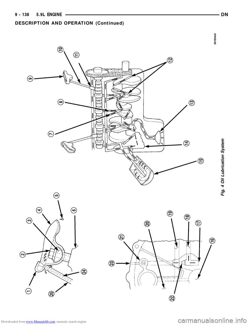
Downloaded from www.Manualslib.com manuals search engine Fig. 4 Oil Lubrication System
9 - 138 5.9L ENGINEDN
DESCRIPTION AND OPERATION (Continued)
Page 140 of 193
Downloaded from www.Manualslib.com manuals search engine EXHAUST MANIFOLD
DESCRIPTION
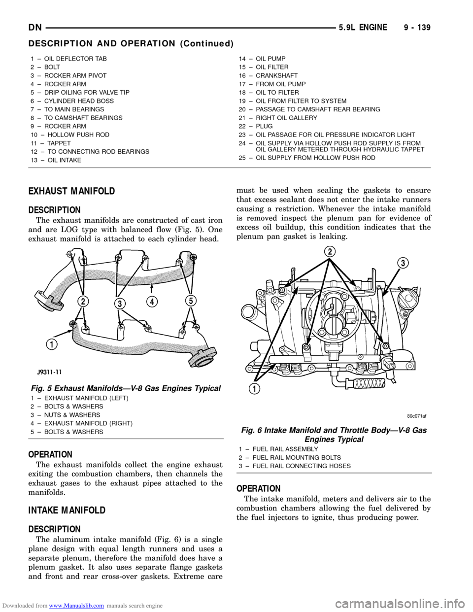
The exhaust manifolds are constructed of cast iron
and are LOG type with balanced flow (Fig. 5). One
exhaust manifold is attached to each cylinder head.
OPERATION
The exhaust manifolds collect the engine exhaust
exiting the combustion chambers, then channels the
exhaust gases to the exhaust pipes attached to the
manifolds.
INTAKE MANIFOLD
DESCRIPTION
The aluminum intake manifold (Fig. 6) is a single
plane design with equal length runners and uses a
separate plenum, therefore the manifold does have a
plenum gasket. It also uses separate flange gaskets
and front and rear cross-over gaskets. Extreme caremust be used when sealing the gaskets to ensure
that excess sealant does not enter the intake runners
causing a restriction. Whenever the intake manifold
is removed inspect the plenum pan for evidence of
excess oil buildup, this condition indicates that the
plenum pan gasket is leaking.
OPERATION
The intake manifold, meters and delivers air to the
combustion chambers allowing the fuel delivered by
the fuel injectors to ignite, thus producing power.
1 ± OIL DEFLECTOR TAB
2 ± BOLT
3 ± ROCKER ARM PIVOT
4 ± ROCKER ARM
5 ± DRIP OILING FOR VALVE TIP
6 ± CYLINDER HEAD BOSS
7 ± TO MAIN BEARINGS
8 ± TO CAMSHAFT BEARINGS
9 ± ROCKER ARM
10 ± HOLLOW PUSH ROD
11 ± TAPPET
12 ± TO CONNECTING ROD BEARINGS
13 ± OIL INTAKE14 ± OIL PUMP
15 ± OIL FILTER
16 ± CRANKSHAFT
17 ± FROM OIL PUMP
18 ± OIL TO FILTER
19 ± OIL FROM FILTER TO SYSTEM
20 ± PASSAGE TO CAMSHAFT REAR BEARING
21 ± RIGHT OIL GALLERY
22 ± PLUG
23 ± OIL PASSAGE FOR OIL PRESSURE INDICATOR LIGHT
24 ± OIL SUPPLY VIA HOLLOW PUSH ROD SUPPLY IS FROM
OIL GALLERY METERED THROUGH HYDRAULIC TAPPET
25 ± OIL SUPPLY FROM HOLLOW PUSH ROD
Fig. 5 Exhaust ManifoldsÐV-8 Gas Engines Typical
1 ± EXHAUST MANIFOLD (LEFT)
2 ± BOLTS & WASHERS
3 ± NUTS & WASHERS
4 ± EXHAUST MANIFOLD (RIGHT)
5 ± BOLTS & WASHERS
Fig. 6 Intake Manifold and Throttle BodyÐV-8 Gas
Engines Typical
1 ± FUEL RAIL ASSEMBLY
2 ± FUEL RAIL MOUNTING BOLTS
3 ± FUEL RAIL CONNECTING HOSES
DN5.9L ENGINE 9 - 139
DESCRIPTION AND OPERATION (Continued)