Light DODGE DURANGO 1998 1.G User Guide
[x] Cancel search | Manufacturer: DODGE, Model Year: 1998, Model line: DURANGO, Model: DODGE DURANGO 1998 1.GPages: 193, PDF Size: 5.65 MB
Page 47 of 193
Downloaded from www.Manualslib.com manuals search engine INSTALLATION
(1) Install hydraulic lash adjuster making sure
adjusters are at least partially full of oil. This can be
verified by little or no plunger travel when lash
adjuster is depressed.
(2) Install rocker arm(s). Refer to procedure in this
section.
(3) Install cylinder head cover(s). Refer to proce-
dure in this section.
CRANKSHAFT DAMPER
REMOVAL
(1) Disconnect negative cable from battery.
(2) Remove accessory drive belt. Refer to COOL-
ING SYSTEM.
(3) Drain cooling system. Refer to COOLING SYS-
TEM.
(4) Remove radiator upper hose.
(5) Remove upper fan shroud. Refer to COOLING
SYSTEM.
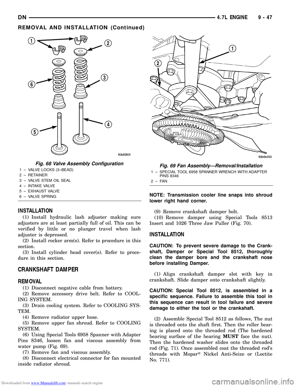
(6) Using Special Tools 6958 Spanner with Adapter
Pins 8346, loosen fan and viscous assembly from
water pump (Fig. 69).
(7) Remove fan and viscous assembly.
(8) Disconnect electrical connector for fan mounted
inside radiator shroud.NOTE: Transmission cooler line snaps into shroud
lower right hand corner.
(9) Remove crankshaft damper bolt.
(10) Remove damper using Special Tools 8513
Insert and 1026 Three Jaw Puller (Fig. 70).
INSTALLATION
CAUTION: To prevent severe damage to the Crank-
shaft, Damper or Special Tool 8512, thoroughly
clean the damper bore and the crankshaft nose
before installing Damper.
(1) Align crankshaft damper slot with key in
crankshaft. Slide damper onto crankshaft slightly.
CAUTION: Special Tool 8512, is assembled in a
specific sequence. Failure to assemble this tool in
this sequence can result in tool failure and severe
damage to either the tool or the crankshaft.
(2) Assemble Special Tool 8512 as follows, The nut
is threaded onto the shaft first. Then the roller bear-
ing is placed onto the threaded rod (The hardened
bearing surface of the bearingMUSTface the nut).
Then the hardened washer slides onto the threaded
rod (Fig. 71). Once assembled coat the threaded rod's
threads with MopartNickel Anti-Seize or (Loctite
No. 771).
Fig. 68 Valve Assembly Configuration
1 ± VALVE LOCKS (3±BEAD)
2 ± RETAINER
3 ± VALVE STEM OIL SEAL
4 ± INTAKE VALVE
5 ± EXHAUST VALVE
6 ± VALVE SPRINGFig. 69 Fan AssemblyÐRemoval/Installation
1 ± SPECIAL TOOL 6958 SPANNER WRENCH WITH ADAPTER
PINS 8346
2±FAN
DN4.7L ENGINE 9 - 47
REMOVAL AND INSTALLATION (Continued)
Page 52 of 193
Downloaded from www.Manualslib.com manuals search engine INSPECTION OF COMPONENTS
Inspect the following components:
²Sprockets for excessive tooth wear. Some tooth
markings are normal and not a cause for sprocket
replacement.
²Idler sprocket assembly bushing and shaft for
excessive wear.
²Idler sprocket assembly spline joint. The joint
should be tight with no backlash or axial movement.
²Chain guides and tensioner arms. Replace these
parts if grooving in plastic face is more than 1 mm
(0.039 in.) deep. If plastic face is severely grooved or
melted, the tensioner lube jet may be clogged. The
tensioner should be replaced.
²secondary chain tensioner piston and ratcheting
device. Inspect for evidence of heavy contact between
tensioner piston and tensioner arm. If this condition
exist the tensioner tensioner arm and chain should
be replaced.²Primary chain tensioner plastic faces. Replace as
required.
INSTALLATION
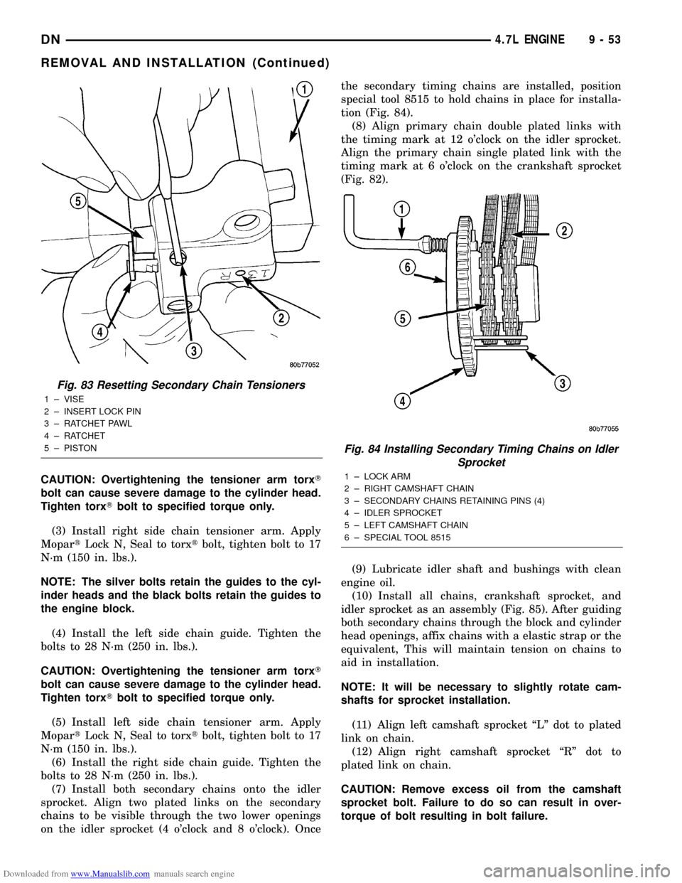
(1) Using a vise, lightly compress the secondary
chain tensioner piston until the piston step is flush
with the tensioner body. Using a pin or suitable tool,
release ratchet pawl by pulling pawl back against
spring force through access hole on side of tensioner.
While continuing to hold pawl back, Push ratchet
device to approximately 2 mm from the tensioner
body. Install Special Tool 8514 lock pin into hole on
front of tensioner. Slowly open vise to transfer piston
spring force to lock pin (Fig. 83).
(2) Position primary chain tensioner over oil pump
and insert bolts into lower two holes on tensioner
bracket. Tighten bolts to 28 N´m (250 in. lbs.).
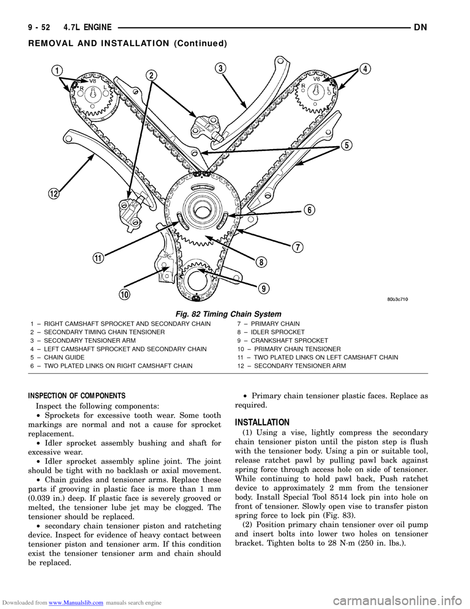
Fig. 82 Timing Chain System
1 ± RIGHT CAMSHAFT SPROCKET AND SECONDARY CHAIN
2 ± SECONDARY TIMING CHAIN TENSIONER
3 ± SECONDARY TENSIONER ARM
4 ± LEFT CAMSHAFT SPROCKET AND SECONDARY CHAIN
5 ± CHAIN GUIDE
6 ± TWO PLATED LINKS ON RIGHT CAMSHAFT CHAIN7 ± PRIMARY CHAIN
8 ± IDLER SPROCKET
9 ± CRANKSHAFT SPROCKET
10 ± PRIMARY CHAIN TENSIONER
11 ± TWO PLATED LINKS ON LEFT CAMSHAFT CHAIN
12 ± SECONDARY TENSIONER ARM
9 - 52 4.7L ENGINEDN
REMOVAL AND INSTALLATION (Continued)
Page 53 of 193
Downloaded from www.Manualslib.com manuals search engine CAUTION: Overtightening the tensioner arm torxT
bolt can cause severe damage to the cylinder head.
Tighten torxTbolt to specified torque only.
(3) Install right side chain tensioner arm. Apply
MopartLock N, Seal to torxtbolt, tighten bolt to 17
N´m (150 in. lbs.).
NOTE: The silver bolts retain the guides to the cyl-
inder heads and the black bolts retain the guides to
the engine block.
(4) Install the left side chain guide. Tighten the
bolts to 28 N´m (250 in. lbs.).
CAUTION: Overtightening the tensioner arm torxT
bolt can cause severe damage to the cylinder head.
Tighten torxTbolt to specified torque only.
(5) Install left side chain tensioner arm. Apply
MopartLock N, Seal to torxtbolt, tighten bolt to 17
N´m (150 in. lbs.).
(6) Install the right side chain guide. Tighten the
bolts to 28 N´m (250 in. lbs.).
(7) Install both secondary chains onto the idler
sprocket. Align two plated links on the secondary
chains to be visible through the two lower openings
on the idler sprocket (4 o'clock and 8 o'clock). Oncethe secondary timing chains are installed, position
special tool 8515 to hold chains in place for installa-
tion (Fig. 84).
(8) Align primary chain double plated links with
the timing mark at 12 o'clock on the idler sprocket.
Align the primary chain single plated link with the
timing mark at 6 o'clock on the crankshaft sprocket
(Fig. 82).
(9) Lubricate idler shaft and bushings with clean
engine oil.
(10) Install all chains, crankshaft sprocket, and
idler sprocket as an assembly (Fig. 85). After guiding
both secondary chains through the block and cylinder
head openings, affix chains with a elastic strap or the
equivalent, This will maintain tension on chains to
aid in installation.
NOTE: It will be necessary to slightly rotate cam-
shafts for sprocket installation.
(11) Align left camshaft sprocket ªLº dot to plated
link on chain.
(12) Align right camshaft sprocket ªRº dot to
plated link on chain.
CAUTION: Remove excess oil from the camshaft
sprocket bolt. Failure to do so can result in over-
torque of bolt resulting in bolt failure.
Fig. 83 Resetting Secondary Chain Tensioners
1 ± VISE
2 ± INSERT LOCK PIN
3 ± RATCHET PAWL
4 ± RATCHET
5 ± PISTON
Fig. 84 Installing Secondary Timing Chains on Idler
Sprocket
1 ± LOCK ARM
2 ± RIGHT CAMSHAFT CHAIN
3 ± SECONDARY CHAINS RETAINING PINS (4)
4 ± IDLER SPROCKET
5 ± LEFT CAMSHAFT CHAIN
6 ± SPECIAL TOOL 8515
DN4.7L ENGINE 9 - 53
REMOVAL AND INSTALLATION (Continued)
Page 72 of 193
Downloaded from www.Manualslib.com manuals search engine CAUTION: Special Tool 8512, is assembled in a
specific sequence. Failure to assemble this tool in
this sequence can result in tool failure and severe
damage to either the tool or the crankshaft.(2) Assemble Special Tool 8512 as follows, The nut
is threaded onto the shaft first. Then the roller bear-
ing is placed onto the threaded rod (The hardened
bearing surface of the bearingMUSTface the nut).
Then the hardened washer slides onto the threaded
rod (Fig. 130). Once assembled coat the threaded
rod's threads with MopartNickel Anti-Seize or (Loc-
tite No. 771).
(3) Align crankshaft damper slot with key in
crankshaft. Slide damper onto crankshaft slightly.
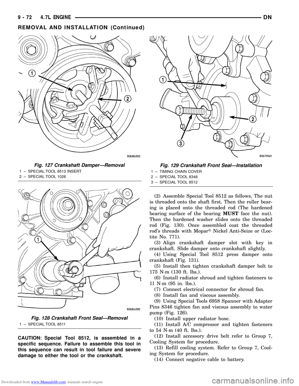
(4) Using Special Tool 8512 press damper onto
crankshaft (Fig. 131).
(5) Install then tighten crankshaft damper bolt to
175 N´m (130 ft. lbs.).
(6) Install radiator shroud and tighten fasteners to
11 N´m (95 in. lbs.).
(7) Connect electrical connector for shroud fan.
(8) Install fan and viscous assembly.
(9) Using Special Tools 6958 Spanner with Adapter
Pins 8346 tighten fan and viscous assembly to water
pump (Fig. 126).
(10) Install upper radiator hose.
(11) Install A/C compressor and tighten fasteners
to 54 N´m (40 ft. lbs.).
(12) Install accessory drive belt refer to Group 7,
Cooling System for procedure.
(13) Refill cooling system. Refer to Group 7, Cool-
ing System for procedure.
(14) Connect negative cable to battery.
Fig. 127 Crankshaft DamperÐRemoval
1 ± SPECIAL TOOL 8513 INSERT
2 ± SPECIAL TOOL 1026
Fig. 128 Crankshaft Front SealÐRemoval
1 ± SPECIAL TOOL 8511
Fig. 129 Crankshaft Front SealÐInstallation
1 ± TIMING CHAIN COVER
2 ± SPECIAL TOOL 8348
3 ± SPECIAL TOOL 8512
9 - 72 4.7L ENGINEDN
REMOVAL AND INSTALLATION (Continued)
Page 78 of 193
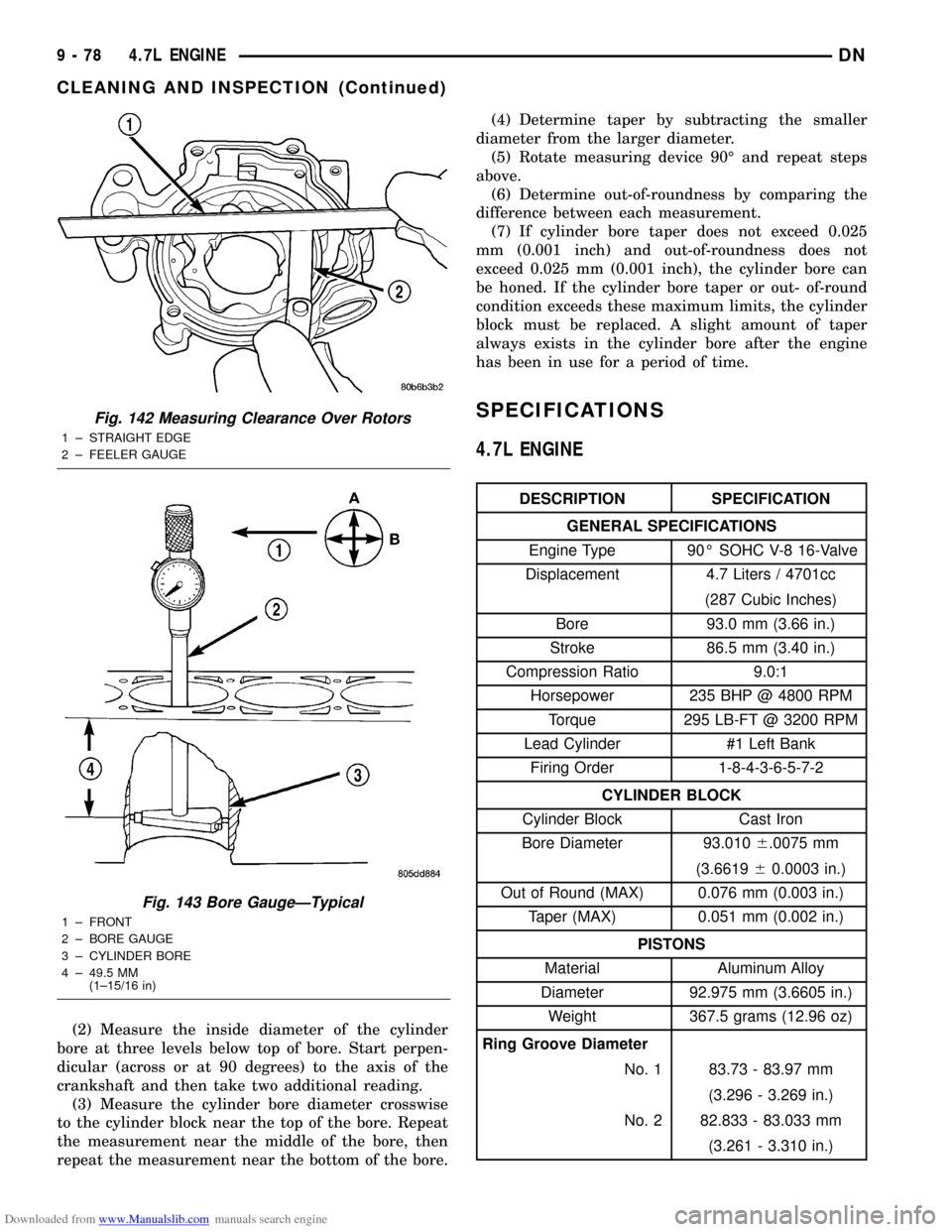
Downloaded from www.Manualslib.com manuals search engine (2) Measure the inside diameter of the cylinder
bore at three levels below top of bore. Start perpen-
dicular (across or at 90 degrees) to the axis of the
crankshaft and then take two additional reading.
(3) Measure the cylinder bore diameter crosswise
to the cylinder block near the top of the bore. Repeat
the measurement near the middle of the bore, then
repeat the measurement near the bottom of the bore.(4) Determine taper by subtracting the smaller
diameter from the larger diameter.
(5) Rotate measuring device 90É and repeat steps
above.
(6) Determine out-of-roundness by comparing the
difference between each measurement.
(7) If cylinder bore taper does not exceed 0.025
mm (0.001 inch) and out-of-roundness does not
exceed 0.025 mm (0.001 inch), the cylinder bore can
be honed. If the cylinder bore taper or out- of-round
condition exceeds these maximum limits, the cylinder
block must be replaced. A slight amount of taper
always exists in the cylinder bore after the engine
has been in use for a period of time.
SPECIFICATIONS
4.7L ENGINE
DESCRIPTION SPECIFICATION
GENERAL SPECIFICATIONS
Engine Type 90É SOHC V-8 16-Valve
Displacement 4.7 Liters / 4701cc
(287 Cubic Inches)
Bore 93.0 mm (3.66 in.)
Stroke 86.5 mm (3.40 in.)
Compression Ratio 9.0:1
Horsepower 235 BHP @ 4800 RPM
Torque 295 LB-FT @ 3200 RPM
Lead Cylinder #1 Left Bank
Firing Order 1-8-4-3-6-5-7-2
CYLINDER BLOCK
Cylinder Block Cast Iron
Bore Diameter 93.0106.0075 mm
(3.661960.0003 in.)
Out of Round (MAX) 0.076 mm (0.003 in.)
Taper (MAX) 0.051 mm (0.002 in.)
PISTONS
Material Aluminum Alloy
Diameter 92.975 mm (3.6605 in.)
Weight 367.5 grams (12.96 oz)
Ring Groove Diameter
No. 1 83.73 - 83.97 mm
(3.296 - 3.269 in.)
No. 2 82.833 - 83.033 mm
(3.261 - 3.310 in.)
Fig. 142 Measuring Clearance Over Rotors
1 ± STRAIGHT EDGE
2 ± FEELER GAUGE
Fig. 143 Bore GaugeÐTypical
1 ± FRONT
2 ± BORE GAUGE
3 ± CYLINDER BORE
4 ± 49.5 MM
(1±15/16 in)
9 - 78 4.7L ENGINEDN
CLEANING AND INSPECTION (Continued)
Page 86 of 193
Downloaded from www.Manualslib.com manuals search engine 5.2L ENGINE
TABLE OF CONTENTS
page page
DESCRIPTION AND OPERATION
ENGINE................................86
ENGINE LUBRICATION SYSTEM.............87
EXHAUST MANIFOLD.....................89
INTAKE MANIFOLD.......................89
CYLINDER HEAD COVER GASKET...........90
CYLINDER HEAD.........................90
VALVES AND VALVE SPRINGS..............90
ENGINE OIL PAN.........................90
CRANKSHAFT OIL SEALS..................90
PISTON AND CONNECTING ROD............90
CRANKSHAFT MAIN BEARINGS.............91
CRANKSHAFT...........................91
SERVICE PROCEDURES
FORM-IN-PLACE GASKETS.................91
ENGINE PERFORMANCE..................92
ENGINE OIL.............................92
REPAIR DAMAGED OR WORN THREADS......94
CYLINDER BOREÐHONING................94
HYDROSTATIC LOCK.....................95
VALVE TIMING...........................95
VALVE SERVICE.........................95
MEASURING TIMING CHAIN STRETCH........97
PISTONSÐFITTING.......................98
PISTON RINGSÐFITTING..................98
CONNECTING ROD BEARINGSÐFITTING.....100
CRANKSHAFT MAIN BEARINGSÐFITTING....100
REMOVAL AND INSTALLATION
ENGINE MOUNTSÐFRONT................100
ENGINE MOUNTÐREAR..................102
ENGINE ASSEMBLY......................102
INTAKE MANIFOLD......................103
EXHAUST MANIFOLD....................105
CYLINDER HEAD COVER.................106
ROCKER ARMS AND PUSH RODS..........107
VALVE SPRING AND STEM SEAL
REPLACEMENT-IN VEHICLE.............107CYLINDER HEAD........................107
VALVES AND VALVE SPRINGS.............108
HYDRAULIC TAPPETS....................109
VIBRATION DAMPER.....................109
TIMING CHAIN COVER...................110
TIMING CHAIN..........................111
CAMSHAFT............................111
CAMSHAFT BEARINGS...................113
CRANKSHAFT MAIN BEARINGS............113
DISTRIBUTOR DRIVE SHAFT BUSHING......114
OILPAN...............................115
PISTON AND CONNECTING ROD ASSEMBLY . . 116
CRANKSHAFT..........................116
OIL PUMP.............................117
CRANKSHAFT OIL SEALÐFRONT...........117
CRANKSHAFT OIL SEALSÐREAR...........118
ENGINE CORE OIL AND CAMSHAFT PLUGS . . 120
DISASSEMBLY AND ASSEMBLY
VALVE SERVICE........................121
OIL PUMP.............................123
CYLINDER BLOCK.......................124
CLEANING AND INSPECTION
CYLINDER HEAD COVER.................124
CYLINDER HEAD ASSEMBLY..............124
PISTON AND CONNECTING ROD ASSEMBLY . . 124
OILPAN...............................124
OIL PUMP.............................125
CYLINDER BLOCK.......................127
INTAKE MANIFOLD......................127
EXHAUST MANIFOLD....................127
SPECIFICATIONS
5.2L ENGINE SPECIFICATIONS.............128
TORQUE SPECIFICATIONS................132
SPECIAL TOOLS
5.2L ENGINE...........................132
DESCRIPTION AND OPERATION
ENGINE
DESCRIPTION
The 5.2 Liter (318 CID) eight-cylinder engine is a
V-Type lightweight, single cam, overhead valve
engine with hydraulic roller tappets.
The engine lubrication system consists of a rotor
type oil pump and a full flow oil filter.The cylinders are numbered from front to rear; 1,
3, 5, 7 on the left bank and 2, 4, 6, 8 on the right
bank. The firing order is 1-8-4-3-6-5-7-2 (Fig. 1). This
engine is designed for unleaded fuel.
The engine serial number is stamped into a
machined pad located on the left, front corner of the
cylinder block. When component part replacement is
necessary, use the engine type and serial number for
reference (Fig. 2).
9 - 86 5.2L ENGINEDN
Page 89 of 193
Downloaded from www.Manualslib.com manuals search engine EXHAUST MANIFOLD
DESCRIPTION
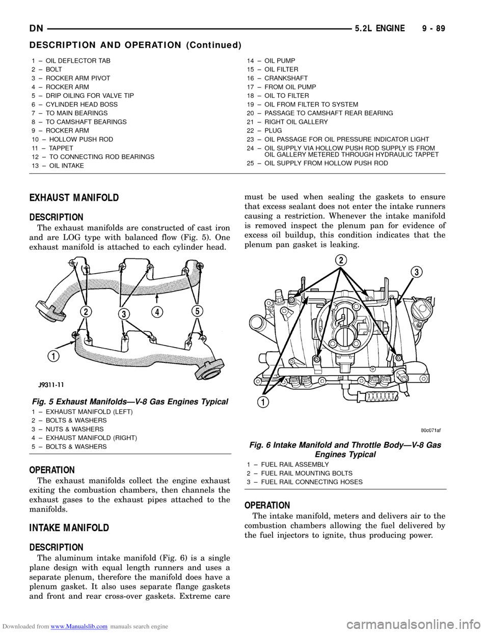
The exhaust manifolds are constructed of cast iron
and are LOG type with balanced flow (Fig. 5). One
exhaust manifold is attached to each cylinder head.
OPERATION
The exhaust manifolds collect the engine exhaust
exiting the combustion chambers, then channels the
exhaust gases to the exhaust pipes attached to the
manifolds.
INTAKE MANIFOLD
DESCRIPTION
The aluminum intake manifold (Fig. 6) is a single
plane design with equal length runners and uses a
separate plenum, therefore the manifold does have a
plenum gasket. It also uses separate flange gaskets
and front and rear cross-over gaskets. Extreme caremust be used when sealing the gaskets to ensure
that excess sealant does not enter the intake runners
causing a restriction. Whenever the intake manifold
is removed inspect the plenum pan for evidence of
excess oil buildup, this condition indicates that the
plenum pan gasket is leaking.
OPERATION
The intake manifold, meters and delivers air to the
combustion chambers allowing the fuel delivered by
the fuel injectors to ignite, thus producing power.
1 ± OIL DEFLECTOR TAB
2 ± BOLT
3 ± ROCKER ARM PIVOT
4 ± ROCKER ARM
5 ± DRIP OILING FOR VALVE TIP
6 ± CYLINDER HEAD BOSS
7 ± TO MAIN BEARINGS
8 ± TO CAMSHAFT BEARINGS
9 ± ROCKER ARM
10 ± HOLLOW PUSH ROD
11 ± TAPPET
12 ± TO CONNECTING ROD BEARINGS
13 ± OIL INTAKE14 ± OIL PUMP
15 ± OIL FILTER
16 ± CRANKSHAFT
17 ± FROM OIL PUMP
18 ± OIL TO FILTER
19 ± OIL FROM FILTER TO SYSTEM
20 ± PASSAGE TO CAMSHAFT REAR BEARING
21 ± RIGHT OIL GALLERY
22 ± PLUG
23 ± OIL PASSAGE FOR OIL PRESSURE INDICATOR LIGHT
24 ± OIL SUPPLY VIA HOLLOW PUSH ROD SUPPLY IS FROM
OIL GALLERY METERED THROUGH HYDRAULIC TAPPET
25 ± OIL SUPPLY FROM HOLLOW PUSH ROD
Fig. 5 Exhaust ManifoldsÐV-8 Gas Engines Typical
1 ± EXHAUST MANIFOLD (LEFT)
2 ± BOLTS & WASHERS
3 ± NUTS & WASHERS
4 ± EXHAUST MANIFOLD (RIGHT)
5 ± BOLTS & WASHERS
Fig. 6 Intake Manifold and Throttle BodyÐV-8 Gas
Engines Typical
1 ± FUEL RAIL ASSEMBLY
2 ± FUEL RAIL MOUNTING BOLTS
3 ± FUEL RAIL CONNECTING HOSES
DN5.2L ENGINE 9 - 89
DESCRIPTION AND OPERATION (Continued)
Page 91 of 193
Downloaded from www.Manualslib.com manuals search engine CRANKSHAFT MAIN BEARINGS
DESCRIPTION
Main bearings are located in the cylinder block.
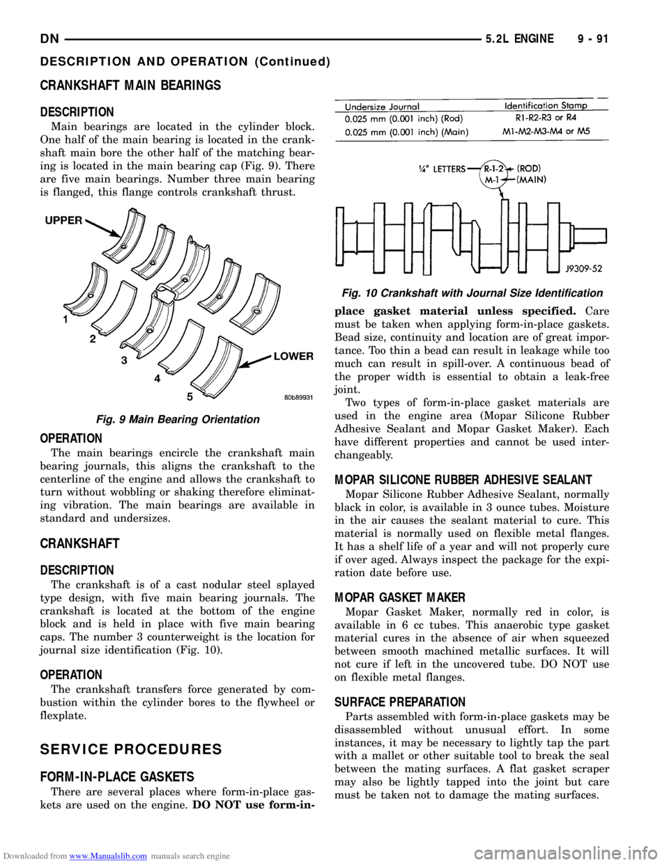
One half of the main bearing is located in the crank-
shaft main bore the other half of the matching bear-
ing is located in the main bearing cap (Fig. 9). There
are five main bearings. Number three main bearing
is flanged, this flange controls crankshaft thrust.
OPERATION
The main bearings encircle the crankshaft main
bearing journals, this aligns the crankshaft to the
centerline of the engine and allows the crankshaft to
turn without wobbling or shaking therefore eliminat-
ing vibration. The main bearings are available in
standard and undersizes.
CRANKSHAFT
DESCRIPTION
The crankshaft is of a cast nodular steel splayed
type design, with five main bearing journals. The
crankshaft is located at the bottom of the engine
block and is held in place with five main bearing
caps. The number 3 counterweight is the location for
journal size identification (Fig. 10).
OPERATION
The crankshaft transfers force generated by com-
bustion within the cylinder bores to the flywheel or
flexplate.
SERVICE PROCEDURES
FORM-IN-PLACE GASKETS
There are several places where form-in-place gas-
kets are used on the engine.DO NOT use form-in-place gasket material unless specified.Care
must be taken when applying form-in-place gaskets.
Bead size, continuity and location are of great impor-
tance. Too thin a bead can result in leakage while too
much can result in spill-over. A continuous bead of
the proper width is essential to obtain a leak-free
joint.
Two types of form-in-place gasket materials are
used in the engine area (Mopar Silicone Rubber
Adhesive Sealant and Mopar Gasket Maker). Each
have different properties and cannot be used inter-
changeably.
MOPAR SILICONE RUBBER ADHESIVE SEALANT
Mopar Silicone Rubber Adhesive Sealant, normally
black in color, is available in 3 ounce tubes. Moisture
in the air causes the sealant material to cure. This
material is normally used on flexible metal flanges.
It has a shelf life of a year and will not properly cure
if over aged. Always inspect the package for the expi-
ration date before use.
MOPAR GASKET MAKER
Mopar Gasket Maker, normally red in color, is
available in 6 cc tubes. This anaerobic type gasket
material cures in the absence of air when squeezed
between smooth machined metallic surfaces. It will
not cure if left in the uncovered tube. DO NOT use
on flexible metal flanges.
SURFACE PREPARATION
Parts assembled with form-in-place gaskets may be
disassembled without unusual effort. In some
instances, it may be necessary to lightly tap the part
with a mallet or other suitable tool to break the seal
between the mating surfaces. A flat gasket scraper
may also be lightly tapped into the joint but care
must be taken not to damage the mating surfaces.
Fig. 9 Main Bearing Orientation
Fig. 10 Crankshaft with Journal Size Identification
DN5.2L ENGINE 9 - 91
DESCRIPTION AND OPERATION (Continued)
Page 94 of 193
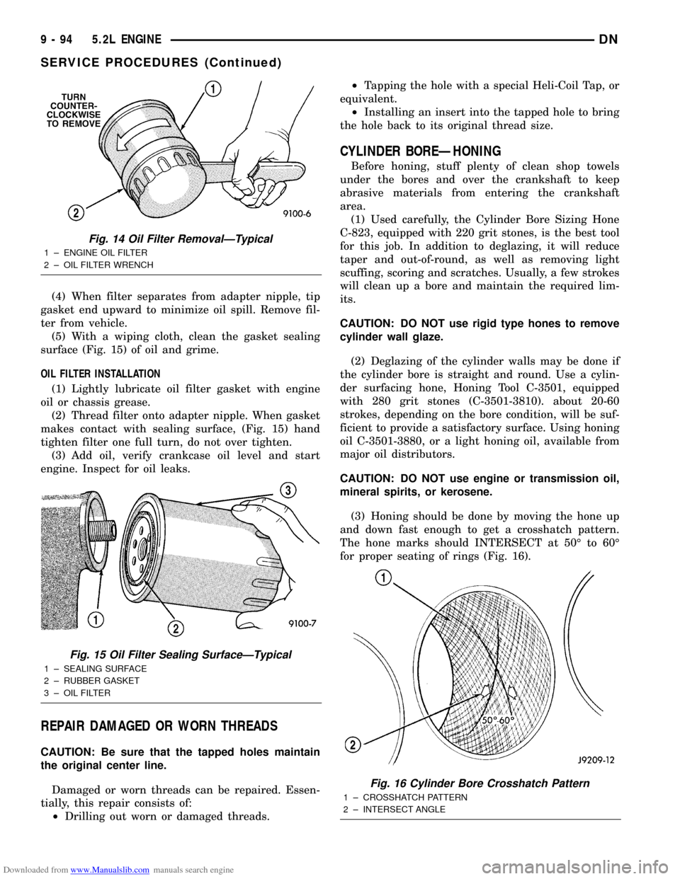
Downloaded from www.Manualslib.com manuals search engine (4) When filter separates from adapter nipple, tip
gasket end upward to minimize oil spill. Remove fil-
ter from vehicle.
(5) With a wiping cloth, clean the gasket sealing
surface (Fig. 15) of oil and grime.
OIL FILTER INSTALLATION
(1) Lightly lubricate oil filter gasket with engine
oil or chassis grease.
(2) Thread filter onto adapter nipple. When gasket
makes contact with sealing surface, (Fig. 15) hand
tighten filter one full turn, do not over tighten.
(3) Add oil, verify crankcase oil level and start
engine. Inspect for oil leaks.
REPAIR DAMAGED OR WORN THREADS
CAUTION: Be sure that the tapped holes maintain
the original center line.
Damaged or worn threads can be repaired. Essen-
tially, this repair consists of:
²Drilling out worn or damaged threads.²Tapping the hole with a special Heli-Coil Tap, or
equivalent.
²Installing an insert into the tapped hole to bring
the hole back to its original thread size.
CYLINDER BOREÐHONING
Before honing, stuff plenty of clean shop towels
under the bores and over the crankshaft to keep
abrasive materials from entering the crankshaft
area.
(1) Used carefully, the Cylinder Bore Sizing Hone
C-823, equipped with 220 grit stones, is the best tool
for this job. In addition to deglazing, it will reduce
taper and out-of-round, as well as removing light
scuffing, scoring and scratches. Usually, a few strokes
will clean up a bore and maintain the required lim-
its.
CAUTION: DO NOT use rigid type hones to remove
cylinder wall glaze.
(2) Deglazing of the cylinder walls may be done if
the cylinder bore is straight and round. Use a cylin-
der surfacing hone, Honing Tool C-3501, equipped
with 280 grit stones (C-3501-3810). about 20-60
strokes, depending on the bore condition, will be suf-
ficient to provide a satisfactory surface. Using honing
oil C-3501-3880, or a light honing oil, available from
major oil distributors.
CAUTION: DO NOT use engine or transmission oil,
mineral spirits, or kerosene.
(3) Honing should be done by moving the hone up
and down fast enough to get a crosshatch pattern.
The hone marks should INTERSECT at 50É to 60É
for proper seating of rings (Fig. 16).
Fig. 14 Oil Filter RemovalÐTypical
1 ± ENGINE OIL FILTER
2 ± OIL FILTER WRENCH
Fig. 15 Oil Filter Sealing SurfaceÐTypical
1 ± SEALING SURFACE
2 ± RUBBER GASKET
3 ± OIL FILTER
Fig. 16 Cylinder Bore Crosshatch Pattern
1 ± CROSSHATCH PATTERN
2 ± INTERSECT ANGLE
9 - 94 5.2L ENGINEDN
SERVICE PROCEDURES (Continued)
Page 97 of 193
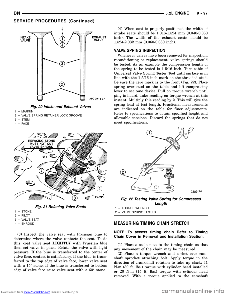
Downloaded from www.Manualslib.com manuals search engine (3) Inspect the valve seat with Prussian blue to
determine where the valve contacts the seat. To do
this, coat valve seatLIGHTLYwith Prussian blue
then set valve in place. Rotate the valve with light
pressure. If the blue is transferred to the center of
valve face, contact is satisfactory. If the blue is trans-
ferred to the top edge of valve face, lower valve seat
with a 15É stone. If the blue is transferred to bottom
edge of valve face raise valve seat with a 60É stone.(4) When seat is properly positioned the width of
intake seats should be 1.016-1.524 mm (0.040-0.060
inch). The width of the exhaust seats should be
1.524-2.032 mm (0.060-0.080 inch).
VALVE SPRING INSPECTION
Whenever valves have been removed for inspection,
reconditioning or replacement, valve springs should
be tested. As an example the compression length of
the spring to be tested is 1-5/16 inch. Turn table of
Universal Valve Spring Tester Tool until surface is in
line with the 1-5/16 inch mark on the threaded stud.
Be sure the zero mark is to the front (Fig. 22). Place
spring over stud on the table and lift compressing
lever to set tone device. Pull on torque wrench until
ping is heard. Take reading on torque wrench at this
instant. Multiply this reading by 2. This will give the
spring load at test length. Fractional measurements
are indicated on the table for finer adjustments.
Refer to specifications to obtain specified height and
allowable tensions. Discard the springs that do not
meet specifications.
MEASURING TIMING CHAIN STRETCH
NOTE: To access timing chain Refer to Timing
Chain Cover in Removal and Installation Section.
(1) Place a scale next to the timing chain so that
any movement of the chain may be measured.
(2) Place a torque wrench and socket over cam-
shaft sprocket attaching bolt. Apply torque in the
direction of crankshaft rotation to take up slack; 41
N´m (30 ft. lbs.) torque with cylinder head installed
or 20 N´m (15 ft. lbs.) torque with cylinder head
removed. With a torque applied to the camshaft
Fig. 20 Intake and Exhaust Valves
1 ± MARGIN
2 ± VALVE SPRING RETAINER LOCK GROOVE
3 ± STEM
4±FACE
Fig. 21 Refacing Valve Seats
1±STONE
2 ± PILOT
3 ± VALVE SEAT
4 ± SHROUD
Fig. 22 Testing Valve Spring for Compressed
Length
1 ± TORQUE WRENCH
2 ± VALVE SPRING TESTER
DN5.2L ENGINE 9 - 97
SERVICE PROCEDURES (Continued)