clock DODGE DURANGO 1998 1.G Workshop Manual
[x] Cancel search | Manufacturer: DODGE, Model Year: 1998, Model line: DURANGO, Model: DODGE DURANGO 1998 1.GPages: 193, PDF Size: 5.65 MB
Page 17 of 193
Downloaded from www.Manualslib.com manuals search engine CRANKCASE OIL LEVEL INSPECTION
CAUTION: Do not overfill crankcase with engine oil,
pressure loss or oil foaming can result.
Inspect engine oil level approximately every 800
kilometers (500 miles). Unless the engine has exhib-
ited loss of oil pressure, run the engine for about five
minutes before checking oil level. Checking engine oil
level on a cold engine is not accurate.
To ensure proper lubrication of an engine, the
engine oil must be maintained at an acceptable level.
The acceptable levels are indicated between the ADD
and SAFE marks on the engine oil dipstick.
(1) Position vehicle on level surface.
(2) With engine OFF, allow approximately ten min-
utes for oil to settle to bottom of crankcase, remove
engine oil dipstick.
(3) Wipe dipstick clean.
(4) Install dipstick and verify it is seated in the
tube.
(5) Remove dipstick, with handle held above the
tip, take oil level reading.
(6) Add oil only if level is below the ADD mark on
dipstick.
ENGINE OIL CHANGE
Change engine oil at mileage and time intervals
described in Maintenance Schedules.
Run engine until achieving normal operating tem-
perature.
(1) Position the vehicle on a level surface and turn
engine off.
(2) Hoist and support vehicle on safety stands.
(3) Remove oil fill cap.
(4) Place a suitable drain pan under crankcase
drain.
(5) Remove drain plug from crankcase and allow
oil to drain into pan. Inspect drain plug threads for
stretching or other damage. Replace drain plug if
damaged.
(6) Install drain plug in crankcase.
(7) Lower vehicle and fill crankcase with specified
type and amount of engine oil described in this sec-
tion.
(8) Install oil fill cap.
(9) Start engine and inspect for leaks.
(10) Stop engine and inspect oil level.
ENGINE OIL FILTER CHANGE
FILTER SPECIFICATION
All engines are equipped with a high quality full-
flow, disposable type oil filter. DaimlerChrysler Cor-
poration recommends a Mopar or equivalent oil filter
be used.OIL FILTER REMOVAL
(1) Position a drain pan under the oil filter.
(2) Using a suitable oil filter wrench loosen filter.
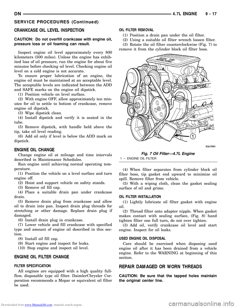
(3) Rotate the oil filter counterclockwise (Fig. 7) to
remove it from the cylinder block oil filter boss.
(4) When filter separates from cylinder block oil
filter boss, tip gasket end upward to minimize oil
spill. Remove filter from vehicle.
(5) With a wiping cloth, clean the gasket sealing
surface of oil and grime.
OIL FILTER INSTALLATION
(1) Lightly lubricate oil filter gasket with engine
oil.
(2) Thread filter onto adapter nipple. When gasket
makes contact with sealing surface, (Fig. 8) hand
tighten filter one full turn, do not over tighten.
(3) Add oil, verify crankcase oil level and start
engine. Inspect for oil leaks.
USED ENGINE OIL DISPOSAL
Care should be exercised when disposing used
engine oil after it has been drained from a vehicle
engine. Refer to the WARNING at beginning of this
section.REPAIR DAMAGED OR WORN THREADS
CAUTION: Be sure that the tapped holes maintain
the original center line.
Fig. 7 Oil FilterÐ4.7L Engine
1 ± ENGINE OIL FILTER
DN4.7L ENGINE 9 - 17
SERVICE PROCEDURES (Continued)
Page 20 of 193
Downloaded from www.Manualslib.com manuals search engine (3) Note the location of the V8 mark stamped into
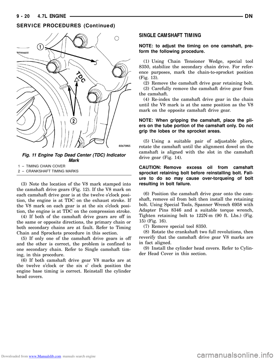
the camshaft drive gears (Fig. 12). If the V8 mark on
each camshaft drive gear is at the twelve o'clock posi-
tion, the engine is at TDC on the exhaust stroke. If
the V8 mark on each gear is at the six o'clock posi-
tion, the engine is at TDC on the compression stroke.
(4) If both of the camshaft drive gears are off in
the same or opposite directions, the primary chain or
both secondary chains are at fault. Refer to Timing
Chain and Sprockets procedure in this section.
(5) If only one of the camshaft drive gears is off
and the other is correct, the problem is confined to
one secondary chain. Refer to Single camshaft tim-
ing, in this procedure.
(6) If both camshaft drive gear V8 marks are at
the twelve o'clock or the six o' clock position the
engine base timing is correct. Reinstall the cylinder
head covers.
SINGLE CAMSHAFT TIMING
NOTE: to adjust the timing on one camshaft, pre-
form the following procedure.
(1) Using Chain Tensioner Wedge, special tool
8350, stabilize the secondary chain drive. For refer-
ence purposes, mark the chain-to-sprocket position
(Fig. 13).
(2) Remove the camshaft drive gear retaining bolt.
(3) Carefully remove the camshaft drive gear from
the camshaft.
(4) Re-index the camshaft drive gear in the chain
until the V8 mark is at the same position as the V8
mark on the opposite camshaft drive gear.
NOTE: When gripping the camshaft, place the pli-
ers on the tube portion of the camshaft only. Do not
grip the lobes or the sprocket areas.
(5) Using a suitable pair of adjustable pliers,
rotate the camshaft until the alignment dowel on the
camshaft is aligned with the slot in the camshaft
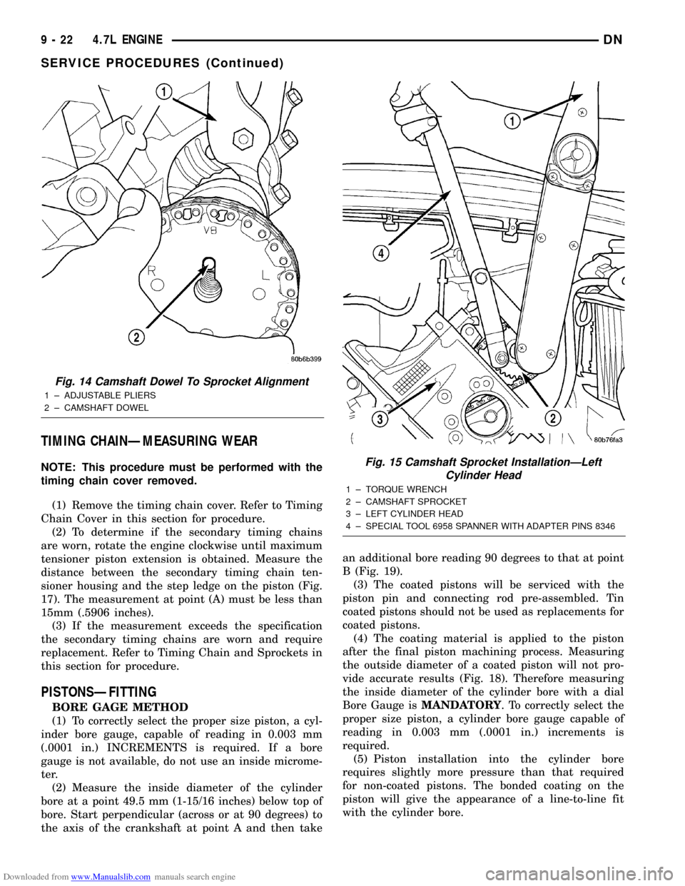
drive gear (Fig. 14).
CAUTION: Remove excess oil from camshaft
sprocket retaining bolt before reinstalling bolt. Fail-
ure to do so may cause over-torqueing of bolt
resulting in bolt failure.
(6) Position the camshaft drive gear onto the cam-
shaft, remove oil from bolt then install the retaining
bolt. Using Special Tools, Spanner Wrench 6958 with
Adapter Pins 8346 and a suitable torque wrench,
Tighten retaining bolt to 122N´m (90 ft. Lbs.) (Fig.
15) (Fig. 16).
(7) Remove special tool 8350.
(8) Rotate the crankshaft two full revolutions, then
reverify that the camshaft drive gear V8 marks are
in fact aligned.
(9) Install the cylinder head covers. Refer to Cylin-
der Head Cover in this section.
Fig. 11 Engine Top Dead Center (TDC) Indicator
Mark
1 ± TIMING CHAIN COVER
2 ± CRANKSHAFT TIMING MARKS
9 - 20 4.7L ENGINEDN
SERVICE PROCEDURES (Continued)
Page 22 of 193
Downloaded from www.Manualslib.com manuals search engine TIMING CHAINÐMEASURING WEAR
NOTE: This procedure must be performed with the
timing chain cover removed.
(1) Remove the timing chain cover. Refer to Timing
Chain Cover in this section for procedure.
(2) To determine if the secondary timing chains
are worn, rotate the engine clockwise until maximum
tensioner piston extension is obtained. Measure the
distance between the secondary timing chain ten-
sioner housing and the step ledge on the piston (Fig.
17). The measurement at point (A) must be less than
15mm (.5906 inches).
(3) If the measurement exceeds the specification
the secondary timing chains are worn and require
replacement. Refer to Timing Chain and Sprockets in
this section for procedure.
PISTONSÐFITTING
BORE GAGE METHOD
(1) To correctly select the proper size piston, a cyl-
inder bore gauge, capable of reading in 0.003 mm
(.0001 in.) INCREMENTS is required. If a bore
gauge is not available, do not use an inside microme-
ter.
(2) Measure the inside diameter of the cylinder
bore at a point 49.5 mm (1-15/16 inches) below top of
bore. Start perpendicular (across or at 90 degrees) to
the axis of the crankshaft at point A and then takean additional bore reading 90 degrees to that at point
B (Fig. 19).
(3) The coated pistons will be serviced with the
piston pin and connecting rod pre-assembled. Tin
coated pistons should not be used as replacements for
coated pistons.
(4) The coating material is applied to the piston
after the final piston machining process. Measuring
the outside diameter of a coated piston will not pro-
vide accurate results (Fig. 18). Therefore measuring
the inside diameter of the cylinder bore with a dial
Bore Gauge isMANDATORY. To correctly select the
proper size piston, a cylinder bore gauge capable of
reading in 0.003 mm (.0001 in.) increments is
required.
(5) Piston installation into the cylinder bore
requires slightly more pressure than that required
for non-coated pistons. The bonded coating on the
piston will give the appearance of a line-to-line fit
with the cylinder bore.
Fig. 14 Camshaft Dowel To Sprocket Alignment
1 ± ADJUSTABLE PLIERS
2 ± CAMSHAFT DOWEL
Fig. 15 Camshaft Sprocket InstallationÐLeft
Cylinder Head
1 ± TORQUE WRENCH
2 ± CAMSHAFT SPROCKET
3 ± LEFT CYLINDER HEAD
4 ± SPECIAL TOOL 6958 SPANNER WITH ADAPTER PINS 8346
9 - 22 4.7L ENGINEDN
SERVICE PROCEDURES (Continued)
Page 41 of 193
Downloaded from www.Manualslib.com manuals search engine (4) For rocker arm installation on cylinders 1 and
7 Rotate the crankshaft until cylinder #2 is at TDC
compression stroke.
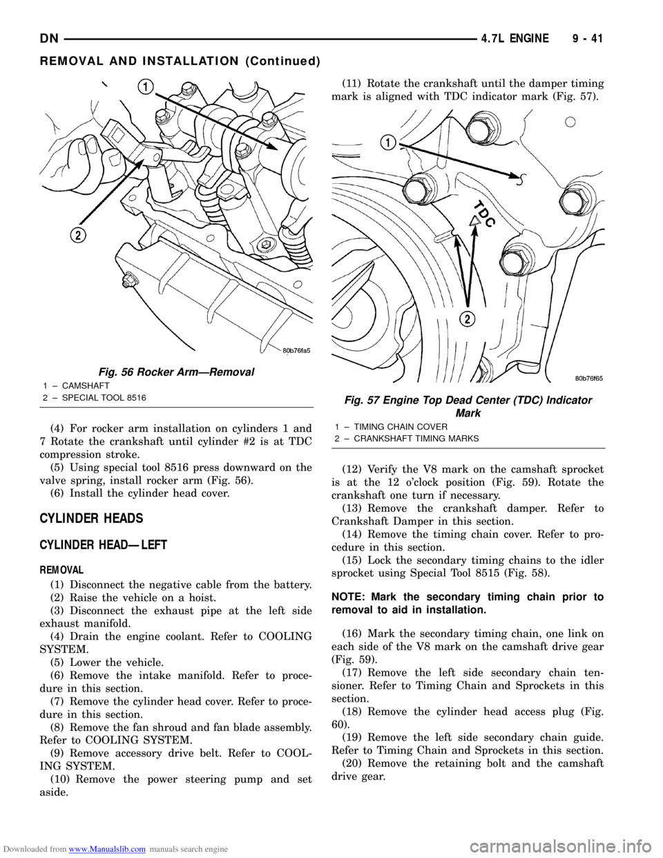
(5) Using special tool 8516 press downward on the
valve spring, install rocker arm (Fig. 56).
(6) Install the cylinder head cover.
CYLINDER HEADS
CYLINDER HEADÐLEFT
REMOVAL
(1) Disconnect the negative cable from the battery.
(2) Raise the vehicle on a hoist.
(3) Disconnect the exhaust pipe at the left side
exhaust manifold.
(4) Drain the engine coolant. Refer to COOLING
SYSTEM.
(5) Lower the vehicle.
(6) Remove the intake manifold. Refer to proce-
dure in this section.
(7) Remove the cylinder head cover. Refer to proce-
dure in this section.
(8) Remove the fan shroud and fan blade assembly.
Refer to COOLING SYSTEM.
(9) Remove accessory drive belt. Refer to COOL-
ING SYSTEM.
(10) Remove the power steering pump and set
aside.(11) Rotate the crankshaft until the damper timing
mark is aligned with TDC indicator mark (Fig. 57).
(12) Verify the V8 mark on the camshaft sprocket
is at the 12 o'clock position (Fig. 59). Rotate the
crankshaft one turn if necessary.
(13) Remove the crankshaft damper. Refer to
Crankshaft Damper in this section.
(14) Remove the timing chain cover. Refer to pro-
cedure in this section.
(15) Lock the secondary timing chains to the idler
sprocket using Special Tool 8515 (Fig. 58).
NOTE: Mark the secondary timing chain prior to
removal to aid in installation.
(16) Mark the secondary timing chain, one link on
each side of the V8 mark on the camshaft drive gear
(Fig. 59).
(17) Remove the left side secondary chain ten-
sioner. Refer to Timing Chain and Sprockets in this
section.
(18) Remove the cylinder head access plug (Fig.
60).
(19) Remove the left side secondary chain guide.
Refer to Timing Chain and Sprockets in this section.
(20) Remove the retaining bolt and the camshaft
drive gear.
Fig. 56 Rocker ArmÐRemoval
1 ± CAMSHAFT
2 ± SPECIAL TOOL 8516
Fig. 57 Engine Top Dead Center (TDC) Indicator
Mark
1 ± TIMING CHAIN COVER
2 ± CRANKSHAFT TIMING MARKS
DN4.7L ENGINE 9 - 41
REMOVAL AND INSTALLATION (Continued)
Page 44 of 193
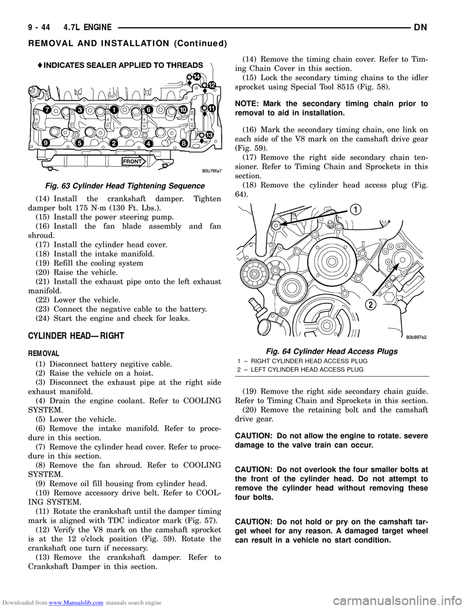
Downloaded from www.Manualslib.com manuals search engine (14) Install the crankshaft damper. Tighten
damper bolt 175 N´m (130 Ft. Lbs.).
(15) Install the power steering pump.
(16) Install the fan blade assembly and fan
shroud.
(17) Install the cylinder head cover.
(18) Install the intake manifold.
(19) Refill the cooling system
(20) Raise the vehicle.
(21) Install the exhaust pipe onto the left exhaust
manifold.
(22) Lower the vehicle.
(23) Connect the negative cable to the battery.
(24) Start the engine and check for leaks.
CYLINDER HEADÐRIGHT
REMOVAL
(1) Disconnect battery negitive cable.
(2) Raise the vehicle on a hoist.
(3) Disconnect the exhaust pipe at the right side
exhaust manifold.
(4) Drain the engine coolant. Refer to COOLING
SYSTEM.
(5) Lower the vehicle.
(6) Remove the intake manifold. Refer to proce-
dure in this section.
(7) Remove the cylinder head cover. Refer to proce-
dure in this section.
(8) Remove the fan shroud. Refer to COOLING
SYSTEM.
(9) Remove oil fill housing from cylinder head.
(10) Remove accessory drive belt. Refer to COOL-
ING SYSTEM.
(11) Rotate the crankshaft until the damper timing
mark is aligned with TDC indicator mark (Fig. 57).
(12) Verify the V8 mark on the camshaft sprocket
is at the 12 o'clock position (Fig. 59). Rotate the
crankshaft one turn if necessary.
(13) Remove the crankshaft damper. Refer to
Crankshaft Damper in this section.(14) Remove the timing chain cover. Refer to Tim-
ing Chain Cover in this section.
(15) Lock the secondary timing chains to the idler
sprocket using Special Tool 8515 (Fig. 58).
NOTE: Mark the secondary timing chain prior to
removal to aid in installation.
(16) Mark the secondary timing chain, one link on
each side of the V8 mark on the camshaft drive gear
(Fig. 59).
(17) Remove the right side secondary chain ten-
sioner. Refer to Timing Chain and Sprockets in this
section.
(18) Remove the cylinder head access plug (Fig.
64).
(19) Remove the right side secondary chain guide.
Refer to Timing Chain and Sprockets in this section.
(20) Remove the retaining bolt and the camshaft
drive gear.
CAUTION: Do not allow the engine to rotate. severe
damage to the valve train can occur.
CAUTION: Do not overlook the four smaller bolts at
the front of the cylinder head. Do not attempt to
remove the cylinder head without removing these
four bolts.
CAUTION: Do not hold or pry on the camshaft tar-
get wheel for any reason. A damaged target wheel
can result in a vehicle no start condition.
Fig. 63 Cylinder Head Tightening Sequence
Fig. 64 Cylinder Head Access Plugs
1 ± RIGHT CYLINDER HEAD ACCESS PLUG
2 ± LEFT CYLINDER HEAD ACCESS PLUG
9 - 44 4.7L ENGINEDN
REMOVAL AND INSTALLATION (Continued)
Page 49 of 193
Downloaded from www.Manualslib.com manuals search engine (3) Install the A/C compressor and generator.
(4) Install crankshaft damper. Refer to procedure
in this section.
(5) Install accessory drive belt tensioner assembly.
Tighten fastener to 54 N´m (40 ft. lbs.).
(6) Install lower radiator hose.
(7) Install both heater hoses.
(8) Install radiator shroud and viscous fan drive
assembly. Refer to Group 7, Cooling System for pro-
cedure.(9) Fill cooling system. Refer to Group 7, Cooling
System for procedures.
(10) Connect the battery negative cable.
TIMING CHAIN AND SPROCKETS
REMOVAL
(1) Disconnect negative cable from battery.
(2) Drain cooling system. Refer to Group 7, Cooling
System for procedures.
(3) Remove right and left cylinder head covers.
Refer to procedure in this section.
(4) Remove radiator fan shroud. Refer to Group 7,
Cooling System for procedure.
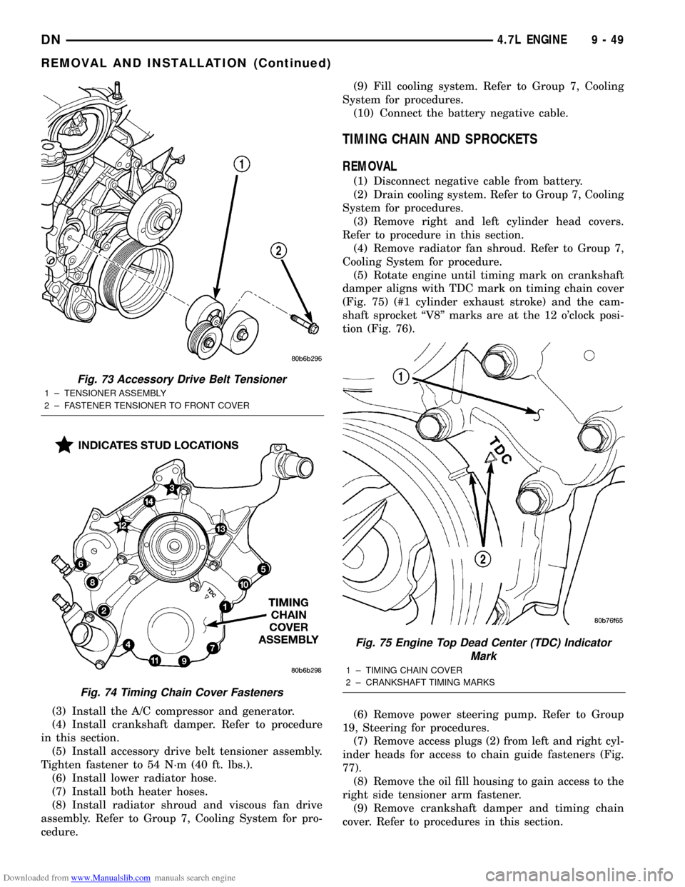
(5) Rotate engine until timing mark on crankshaft
damper aligns with TDC mark on timing chain cover
(Fig. 75) (#1 cylinder exhaust stroke) and the cam-
shaft sprocket ªV8º marks are at the 12 o'clock posi-
tion (Fig. 76).
(6) Remove power steering pump. Refer to Group
19, Steering for procedures.
(7) Remove access plugs (2) from left and right cyl-
inder heads for access to chain guide fasteners (Fig.
77).
(8) Remove the oil fill housing to gain access to the
right side tensioner arm fastener.
(9) Remove crankshaft damper and timing chain
cover. Refer to procedures in this section.
Fig. 73 Accessory Drive Belt Tensioner
1 ± TENSIONER ASSEMBLY
2 ± FASTENER TENSIONER TO FRONT COVER
Fig. 74 Timing Chain Cover Fasteners
Fig. 75 Engine Top Dead Center (TDC) Indicator
Mark
1 ± TIMING CHAIN COVER
2 ± CRANKSHAFT TIMING MARKS
DN4.7L ENGINE 9 - 49
REMOVAL AND INSTALLATION (Continued)
Page 51 of 193
Downloaded from www.Manualslib.com manuals search engine CAUTION: Care should be taken not to damage
camshaft target wheel. Do not hold target wheel
while loosening or tightening camshaft sprocket.
Do not place the target wheel near a magnetic
source of any kind. A damaged or magnetized tar-
get wheel could cause a vehicle no start condition.
CAUTION: Do not forcefully rotate the camshafts or
crankshaft independently of each other. Damaging
intake valve to piston contact will occur. Ensure
negative battery cable is disconnected to guard
against accidental starter engagement.
(13) Remove left and right camshaft sprocket bolts.
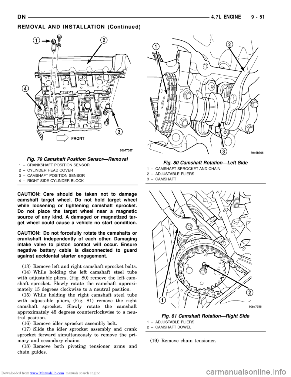
(14) While holding the left camshaft steel tube
with adjustable pliers, (Fig. 80) remove the left cam-
shaft sprocket. Slowly rotate the camshaft approxi-
mately 15 degrees clockwise to a neutral position.
(15) While holding the right camshaft steel tube
with adjustable pliers, (Fig. 81) remove the right
camshaft sprocket. Slowly rotate the camshaft
approximately 45 degrees counterclockwise to a neu-
tral position.
(16) Remove idler sprocket assembly bolt.
(17) Slide the idler sprocket assembly and crank
sprocket forward simultaneously to remove the pri-
mary and secondary chains.
(18) Remove both pivoting tensioner arms and
chain guides.(19) Remove chain tensioner.
Fig. 79 Camshaft Position SensorÐRemoval
1 ± CRANKSHAFT POSITION SENSOR
2 ± CYLINDER HEAD COVER
3 ± CAMSHAFT POSITION SENSOR
4 ± RIGHT SIDE CYLINDER BLOCKFig. 80 Camshaft RotationÐLeft Side
1 ± CAMSHAFT SPROCKET AND CHAIN
2 ± ADJUSTABLE PLIERS
3 ± CAMSHAFT
Fig. 81 Camshaft RotationÐRight Side
1 ± ADJUSTABLE PLIERS
2 ± CAMSHAFT DOWEL
DN4.7L ENGINE 9 - 51
REMOVAL AND INSTALLATION (Continued)
Page 53 of 193
Downloaded from www.Manualslib.com manuals search engine CAUTION: Overtightening the tensioner arm torxT
bolt can cause severe damage to the cylinder head.
Tighten torxTbolt to specified torque only.
(3) Install right side chain tensioner arm. Apply
MopartLock N, Seal to torxtbolt, tighten bolt to 17
N´m (150 in. lbs.).
NOTE: The silver bolts retain the guides to the cyl-
inder heads and the black bolts retain the guides to
the engine block.
(4) Install the left side chain guide. Tighten the
bolts to 28 N´m (250 in. lbs.).
CAUTION: Overtightening the tensioner arm torxT
bolt can cause severe damage to the cylinder head.
Tighten torxTbolt to specified torque only.
(5) Install left side chain tensioner arm. Apply
MopartLock N, Seal to torxtbolt, tighten bolt to 17
N´m (150 in. lbs.).
(6) Install the right side chain guide. Tighten the
bolts to 28 N´m (250 in. lbs.).
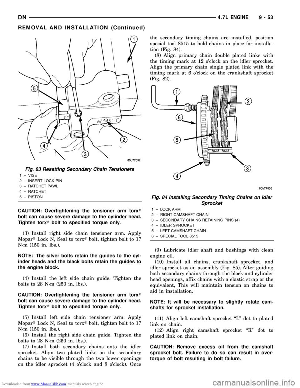
(7) Install both secondary chains onto the idler
sprocket. Align two plated links on the secondary
chains to be visible through the two lower openings
on the idler sprocket (4 o'clock and 8 o'clock). Oncethe secondary timing chains are installed, position
special tool 8515 to hold chains in place for installa-
tion (Fig. 84).
(8) Align primary chain double plated links with
the timing mark at 12 o'clock on the idler sprocket.
Align the primary chain single plated link with the
timing mark at 6 o'clock on the crankshaft sprocket
(Fig. 82).
(9) Lubricate idler shaft and bushings with clean
engine oil.
(10) Install all chains, crankshaft sprocket, and
idler sprocket as an assembly (Fig. 85). After guiding
both secondary chains through the block and cylinder
head openings, affix chains with a elastic strap or the
equivalent, This will maintain tension on chains to
aid in installation.
NOTE: It will be necessary to slightly rotate cam-
shafts for sprocket installation.
(11) Align left camshaft sprocket ªLº dot to plated
link on chain.
(12) Align right camshaft sprocket ªRº dot to
plated link on chain.
CAUTION: Remove excess oil from the camshaft
sprocket bolt. Failure to do so can result in over-
torque of bolt resulting in bolt failure.
Fig. 83 Resetting Secondary Chain Tensioners
1 ± VISE
2 ± INSERT LOCK PIN
3 ± RATCHET PAWL
4 ± RATCHET
5 ± PISTON
Fig. 84 Installing Secondary Timing Chains on Idler
Sprocket
1 ± LOCK ARM
2 ± RIGHT CAMSHAFT CHAIN
3 ± SECONDARY CHAINS RETAINING PINS (4)
4 ± IDLER SPROCKET
5 ± LEFT CAMSHAFT CHAIN
6 ± SPECIAL TOOL 8515
DN4.7L ENGINE 9 - 53
REMOVAL AND INSTALLATION (Continued)
Page 54 of 193
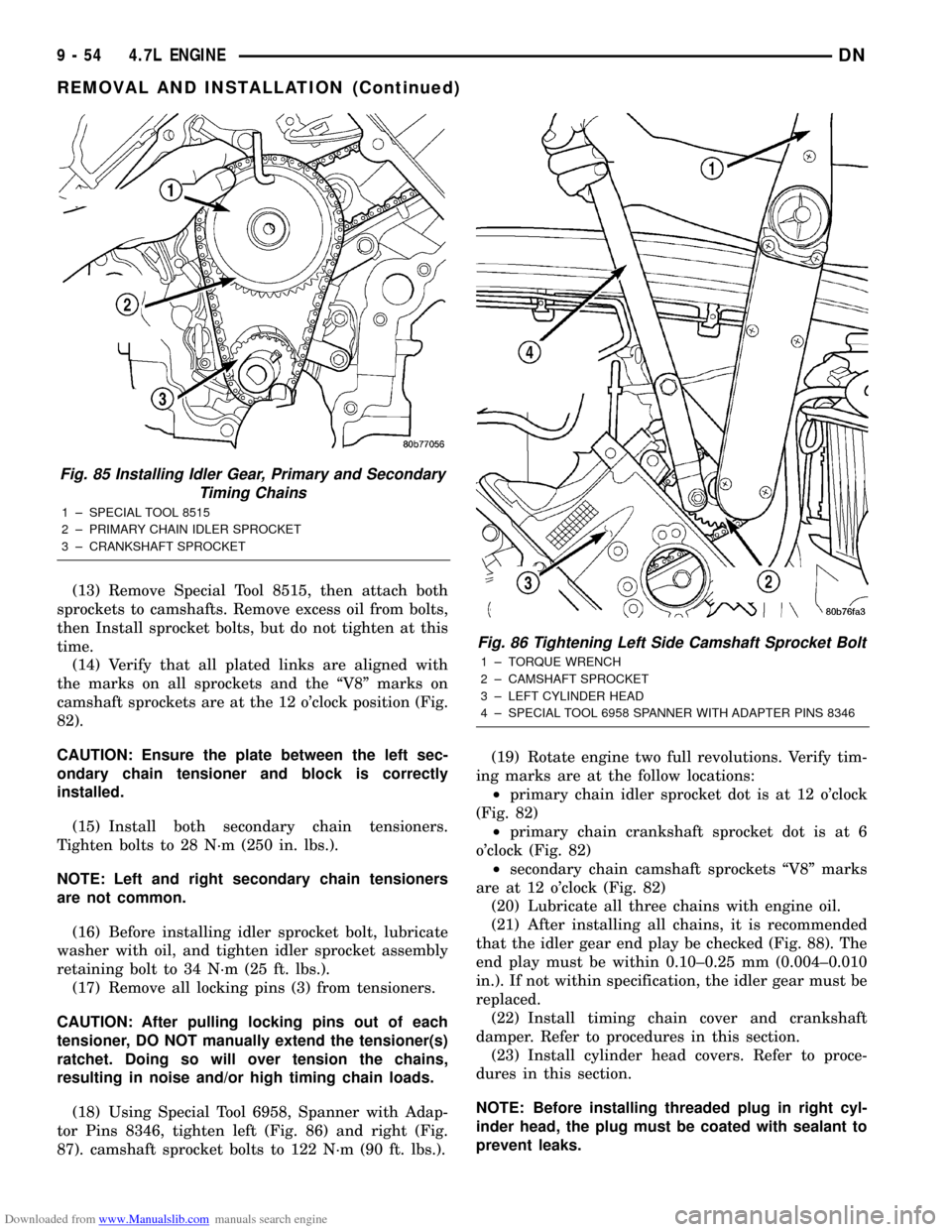
Downloaded from www.Manualslib.com manuals search engine (13) Remove Special Tool 8515, then attach both
sprockets to camshafts. Remove excess oil from bolts,
then Install sprocket bolts, but do not tighten at this
time.
(14) Verify that all plated links are aligned with
the marks on all sprockets and the ªV8º marks on
camshaft sprockets are at the 12 o'clock position (Fig.
82).
CAUTION: Ensure the plate between the left sec-
ondary chain tensioner and block is correctly
installed.
(15) Install both secondary chain tensioners.
Tighten bolts to 28 N´m (250 in. lbs.).
NOTE: Left and right secondary chain tensioners
are not common.
(16) Before installing idler sprocket bolt, lubricate
washer with oil, and tighten idler sprocket assembly
retaining bolt to 34 N´m (25 ft. lbs.).
(17) Remove all locking pins (3) from tensioners.
CAUTION: After pulling locking pins out of each
tensioner, DO NOT manually extend the tensioner(s)
ratchet. Doing so will over tension the chains,
resulting in noise and/or high timing chain loads.
(18) Using Special Tool 6958, Spanner with Adap-
tor Pins 8346, tighten left (Fig. 86) and right (Fig.
87). camshaft sprocket bolts to 122 N´m (90 ft. lbs.).(19) Rotate engine two full revolutions. Verify tim-
ing marks are at the follow locations:
²primary chain idler sprocket dot is at 12 o'clock
(Fig. 82)
²primary chain crankshaft sprocket dot is at 6
o'clock (Fig. 82)
²secondary chain camshaft sprockets ªV8º marks
are at 12 o'clock (Fig. 82)
(20) Lubricate all three chains with engine oil.
(21) After installing all chains, it is recommended
that the idler gear end play be checked (Fig. 88). The
end play must be within 0.10±0.25 mm (0.004±0.010
in.). If not within specification, the idler gear must be
replaced.
(22) Install timing chain cover and crankshaft
damper. Refer to procedures in this section.
(23) Install cylinder head covers. Refer to proce-
dures in this section.
NOTE: Before installing threaded plug in right cyl-
inder head, the plug must be coated with sealant to
prevent leaks.
Fig. 85 Installing Idler Gear, Primary and Secondary
Timing Chains
1 ± SPECIAL TOOL 8515
2 ± PRIMARY CHAIN IDLER SPROCKET
3 ± CRANKSHAFT SPROCKET
Fig. 86 Tightening Left Side Camshaft Sprocket Bolt
1 ± TORQUE WRENCH
2 ± CAMSHAFT SPROCKET
3 ± LEFT CYLINDER HEAD
4 ± SPECIAL TOOL 6958 SPANNER WITH ADAPTER PINS 8346
9 - 54 4.7L ENGINEDN
REMOVAL AND INSTALLATION (Continued)
Page 56 of 193
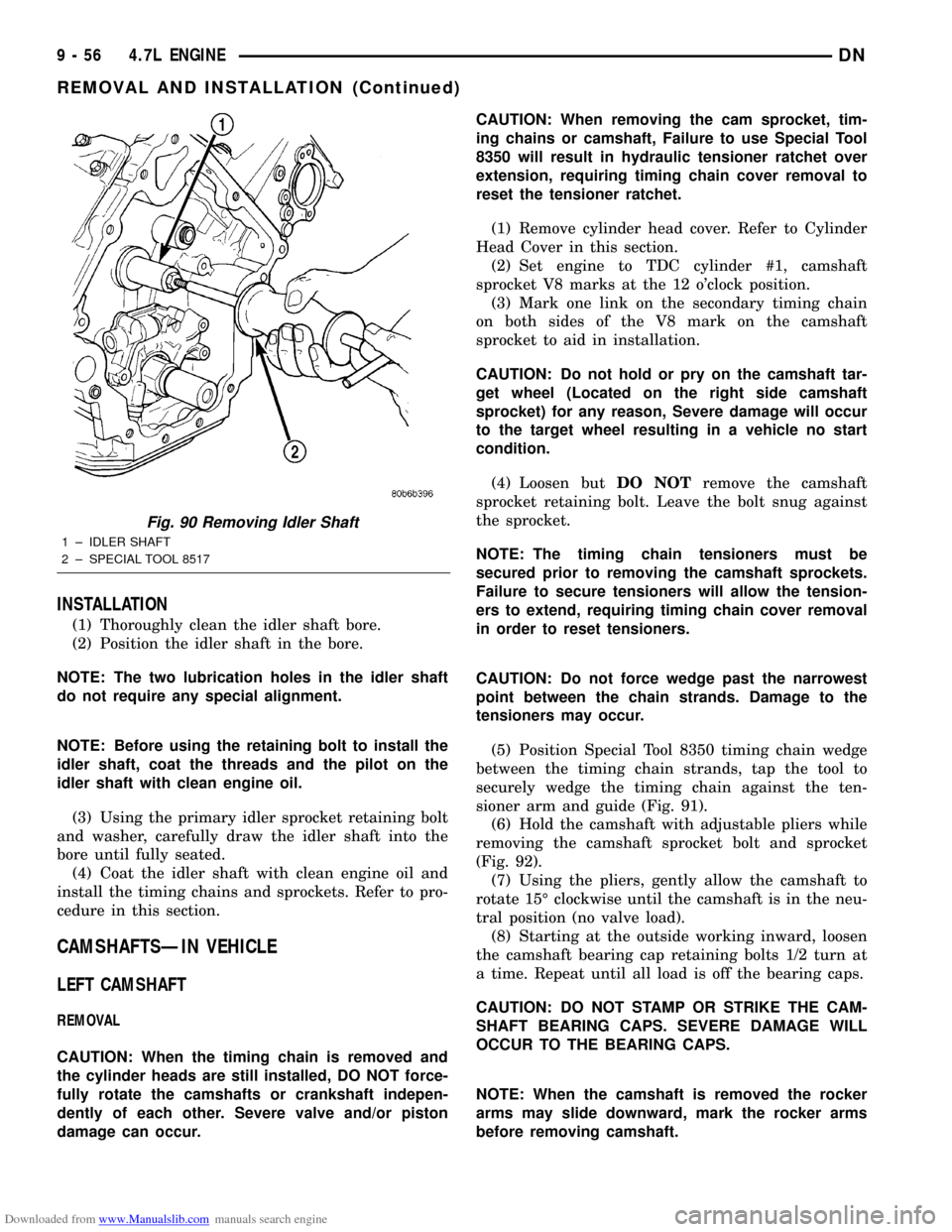
Downloaded from www.Manualslib.com manuals search engine INSTALLATION
(1) Thoroughly clean the idler shaft bore.
(2) Position the idler shaft in the bore.
NOTE: The two lubrication holes in the idler shaft
do not require any special alignment.
NOTE: Before using the retaining bolt to install the
idler shaft, coat the threads and the pilot on the
idler shaft with clean engine oil.
(3) Using the primary idler sprocket retaining bolt
and washer, carefully draw the idler shaft into the
bore until fully seated.
(4) Coat the idler shaft with clean engine oil and
install the timing chains and sprockets. Refer to pro-
cedure in this section.
CAMSHAFTSÐIN VEHICLE
LEFT CAMSHAFT
REMOVAL
CAUTION: When the timing chain is removed and
the cylinder heads are still installed, DO NOT force-
fully rotate the camshafts or crankshaft indepen-
dently of each other. Severe valve and/or piston
damage can occur.CAUTION: When removing the cam sprocket, tim-
ing chains or camshaft, Failure to use Special Tool
8350 will result in hydraulic tensioner ratchet over
extension, requiring timing chain cover removal to
reset the tensioner ratchet.
(1) Remove cylinder head cover. Refer to Cylinder
Head Cover in this section.
(2) Set engine to TDC cylinder #1, camshaft
sprocket V8 marks at the 12 o'clock position.
(3) Mark one link on the secondary timing chain
on both sides of the V8 mark on the camshaft
sprocket to aid in installation.
CAUTION: Do not hold or pry on the camshaft tar-
get wheel (Located on the right side camshaft
sprocket) for any reason, Severe damage will occur
to the target wheel resulting in a vehicle no start
condition.
(4) Loosen butDO NOTremove the camshaft
sprocket retaining bolt. Leave the bolt snug against
the sprocket.
NOTE: The timing chain tensioners must be
secured prior to removing the camshaft sprockets.
Failure to secure tensioners will allow the tension-
ers to extend, requiring timing chain cover removal
in order to reset tensioners.
CAUTION: Do not force wedge past the narrowest
point between the chain strands. Damage to the
tensioners may occur.
(5) Position Special Tool 8350 timing chain wedge
between the timing chain strands, tap the tool to
securely wedge the timing chain against the ten-
sioner arm and guide (Fig. 91).
(6) Hold the camshaft with adjustable pliers while
removing the camshaft sprocket bolt and sprocket
(Fig. 92).
(7) Using the pliers, gently allow the camshaft to
rotate 15É clockwise until the camshaft is in the neu-
tral position (no valve load).
(8) Starting at the outside working inward, loosen
the camshaft bearing cap retaining bolts 1/2 turn at
a time. Repeat until all load is off the bearing caps.
CAUTION: DO NOT STAMP OR STRIKE THE CAM-
SHAFT BEARING CAPS. SEVERE DAMAGE WILL
OCCUR TO THE BEARING CAPS.
NOTE: When the camshaft is removed the rocker
arms may slide downward, mark the rocker arms
before removing camshaft.
Fig. 90 Removing Idler Shaft
1 ± IDLER SHAFT
2 ± SPECIAL TOOL 8517
9 - 56 4.7L ENGINEDN
REMOVAL AND INSTALLATION (Continued)