clock DODGE DURANGO 2012 3.G User Guide
[x] Cancel search | Manufacturer: DODGE, Model Year: 2012, Model line: DURANGO, Model: DODGE DURANGO 2012 3.GPages: 140, PDF Size: 4.3 MB
Page 11 of 140
• In case the Key Fob battery is dead,use the emergency key to open the
door. If the vehicle is equipped with
Keyless Enter-N-Go™, remove the
ENGINE START/STOP button by
inserting the metal part of the
emergency key under the chrome bezel
at the 6 o’clock position and gently pry
the button loose.
NOTE: The ENGINE START/STOP button should only be removed or inserted with the
ignition in the LOCK position (OFF position for Keyless Enter-N-Go™).
• With the ENGINE START/STOP buttonremoved, start the vehicle by inserting
the Key Fob in the ignition and turning
to the Start position.
CAUTION!
• If your vehicle battery becomes low or dead, your Key Fob will become lockedin the ignition.
• Do not attempt to remove the Key Fob while in this condition, damage could occur to the Key Fob or ignition module. Only remove the emergency key for
locking and unlocking the doors.
• Leave the Key Fob in the ignition and either: • Jump Start the vehicle.
• Charge the battery.
• Contact your dealer for assistance on how to remove the Key Fob usingthe manual over ride method.
GETTING STARTED
9
Page 14 of 140
• If a Key Fob is detected in the vehicle when locking the vehicle using the power doorlock switch, the doors and liftgate will unlock and the horn will chirp three times. On
the third attempt, your Key Fob can be locked inside the vehicle.
• After pressing the Keyless Enter-N-Go™ LOCK button, you must wait 2 seconds before you can lock or unlock the vehicle using the door handle. This is done to allow
you to check if the vehicle is locked by pulling the door handle, without the vehicle
reacting and unlocking.
• If a Keyless Enter-N-Go™ door handle has not been used for 72 hours, the Keyless Enter-N-Go™ feature for that handle may time out. Pulling the deactivated front door
handle will reactivate the door handle's Keyless Enter-N-Go™ feature.
Lock or Unlock the Liftgate:
• With a valid Keyless Enter-N-Go™ KeyFob within 3 ft (1.0 m) of the liftgate,
press the button located to the right of
the liftgate handle to unlock the
liftgate. Press the button a second
time to lock the liftgate.
NOTE:
• Refer to your Owner's Manual on the DVD for further information.
Installing And Removing The ENGINE START/STOP Button
Installing The Button
• Remove the Key Fob from the ignition switch.
• Insert the ENGINE START/STOP button into the ignition switch with the lettering facing up and readable.
• Press firmly on the center of the button to secure it into position.
Removing The Button • The ENGINE START/STOP button can be removed from the ignition switch for Key Fob use.
• Insert the metal part of the emergency key under the chrome bezel at the 6 o’clock position and gently pry the button
loose.
NOTE:
• The ENGINE START/STOP button should only be removed or inserted with the
ignition in the LOCK position (OFF
position for Keyless Enter-N-Go™).
GETTING STARTED
12
Page 44 of 140
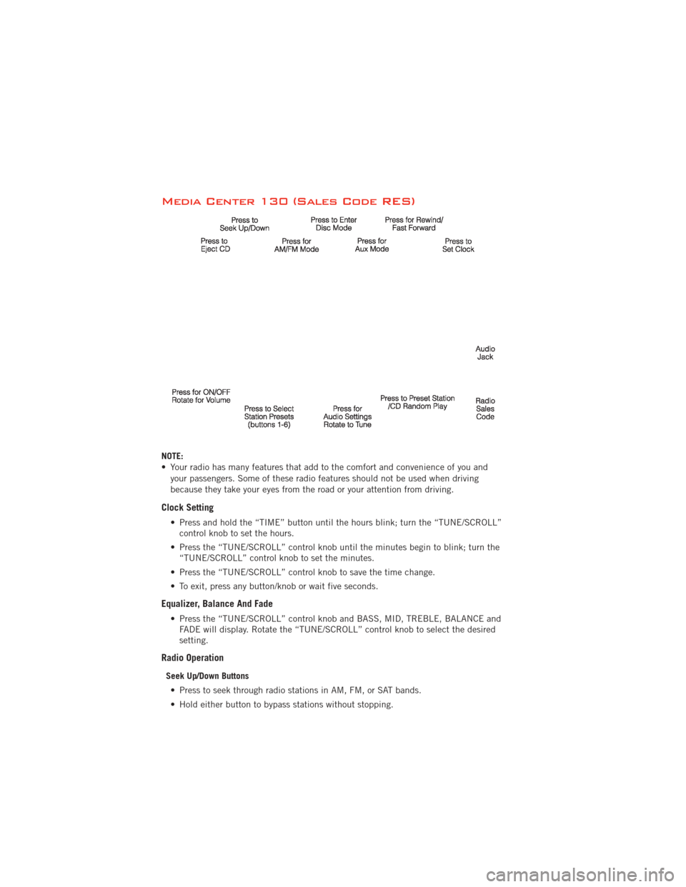
Media Center 130 (Sales Code RES)
NOTE:
• Your radio has many features that add to the comfort and convenience of you andyour passengers. Some of these radio features should not be used when driving
because they take your eyes from the road or your attention from driving.
Clock Setting
• Press and hold the “TIME” button until the hours blink; turn the “TUNE/SCROLL”control knob to set the hours.
• Press the “TUNE/SCROLL” control knob until the minutes begin to blink; turn the “TUNE/SCROLL” control knob to set the minutes.
• Press the “TUNE/SCROLL” control knob to save the time change.
• To exit, press any button/knob or wait five seconds.
Equalizer, Balance And Fade
• Press the “TUNE/SCROLL” control knob and BASS, MID, TREBLE, BALANCE and FADE will display. Rotate the “TUNE/SCROLL” control knob to select the desired
setting.
Radio Operation
Seek Up/Down Buttons
• Press to seek through radio stations in AM, FM, or SAT bands.
• Hold either button to bypass stations without stopping.
ELECTRONICS
42
Page 46 of 140
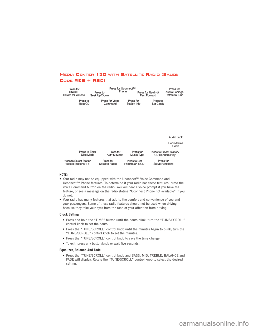
Media Center 130 with Satellite Radio (Sales
Code RES + RSC)
NOTE:
• Your radio may not be equipped with the Uconnect™ Voice Command andUconnect™ Phone features. To determine if your radio has these features, press the
Voice Command button on the radio. You will hear a voice prompt if you have the
feature, or see a message on the radio stating “Uconnect Phone not available” if you
do not.
• Your radio has many features that add to the comfort and convenience of you and your passengers. Some of these radio features should not be used when driving
because they take your eyes from the road or your attention from driving.
Clock Setting
• Press and hold the “TIME” button until the hours blink; turn the “TUNE/SCROLL”control knob to set the hours.
• Press the “TUNE/SCROLL” control knob until the minutes begin to blink; turn the “TUNE/SCROLL” control knob to set the minutes.
• Press the “TUNE/SCROLL” control knob to save the time change.
• To exit, press any button/knob or wait five seconds.
Equalizer, Balance And Fade
• Press the “TUNE/SCROLL” control knob and BASS, MID, TREBLE, BALANCE and FADE will display. Rotate the “TUNE/SCROLL” control knob to select the desired
setting.
ELECTRONICS
44
Page 49 of 140
Clock Setting
• Turn the radio on, then touch the screen where the time is displayed.
• Touch the “USER CLOCK” soft-key (Navigation radio only).
• To adjust the hours, touch either the “HOUR FORWARD” or “HOUR BACKWARD”soft-key.
• To adjust the minutes, touch either the “MINUTE FORWARD” or “MINUTE BACKWARD” soft-key.
• To save the new time setting, touch the screen where the word “Save” is displayed.
Menu
• Press the “MENU” hard-key to access the System Setup menu and the My Files menu.
• Press the “MENU” hard-key in an active mode (SAT, CD, AUX, etc.) in order to change mode specific settings.
Equalizer, Balance And Fade
Audio Control Menu
• Press the “AUDIO” hard-key on the right side of the radio.
• Use either the arrow soft-keys or the cross-hair on the screen to change
Balance and Fade. The “CENTER”
soft-key resets the settings.
• Touch the “Equalizer” soft-key and use either the arrow soft-keys or the sliders on the screen to adjust BASS, MID, and/or TREBLE.
Display Settings
• Press the “MENU” hard-key and touchthe “Display Settings” soft-key to
access the Display Settings menu.
• Select the “Daytime Colors” soft-key to switch to manual daytime mode and to
adjust the brightness of the display
using daytime colors.
• Select the “Nighttime Colors” soft-key to switch to manual nighttime mode and to adjust the brightness of the display using nighttime colors.
•
Select the “Auto Color Mode” soft-key to switch to automatic daytime/nighttime mode
and to control the brightness of the display using the dimmer switch of the vehicle.
• Touch the “EXIT” soft-key to save your settings.
ELECTRONICS
47
Page 57 of 140
• You may experience delays in acquisition of satellite signals when in areas with anobstructed view to the sky, such as garages, tunnels, or large cities with tall
buildings.
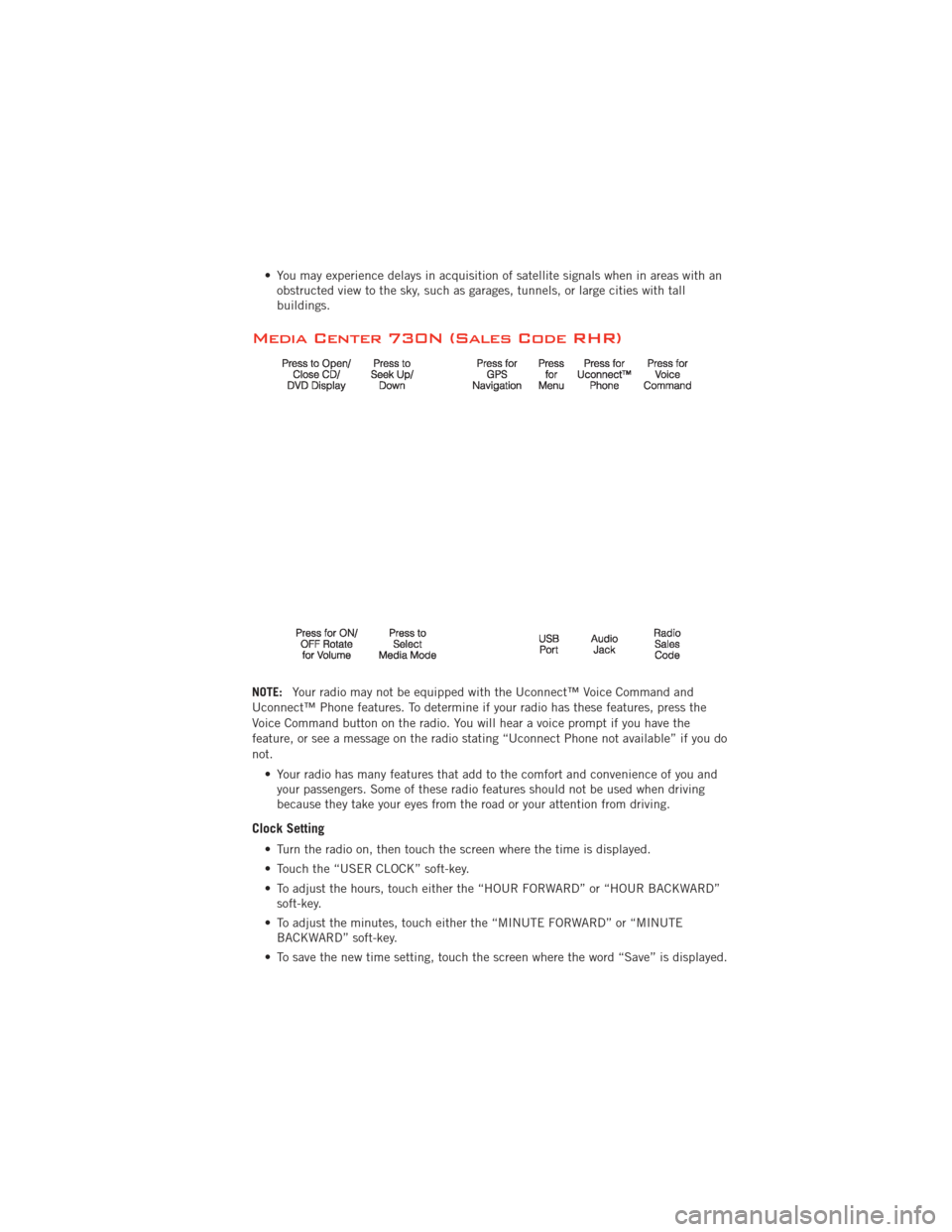
Media Center 730N (Sales Code RHR)
NOTE: Your radio may not be equipped with the Uconnect™ Voice Command and
Uconnect™ Phone features. To determine if your radio has these features, press the
Voice Command button on the radio. You will hear a voice prompt if you have the
feature, or see a message on the radio stating “Uconnect Phone not available” if you do
not.
• Your radio has many features that add to the comfort and convenience of you andyour passengers. Some of these radio features should not be used when driving
because they take your eyes from the road or your attention from driving.
Clock Setting
• Turn the radio on, then touch the screen where the time is displayed.
• Touch the “USER CLOCK” soft-key.
• To adjust the hours, touch either the “HOUR FORWARD” or “HOUR BACKWARD”soft-key.
• To adjust the minutes, touch either the “MINUTE FORWARD” or “MINUTE BACKWARD” soft-key.
• To save the new time setting, touch the screen where the word “Save” is displayed.
ELECTRONICS
55
Page 101 of 140
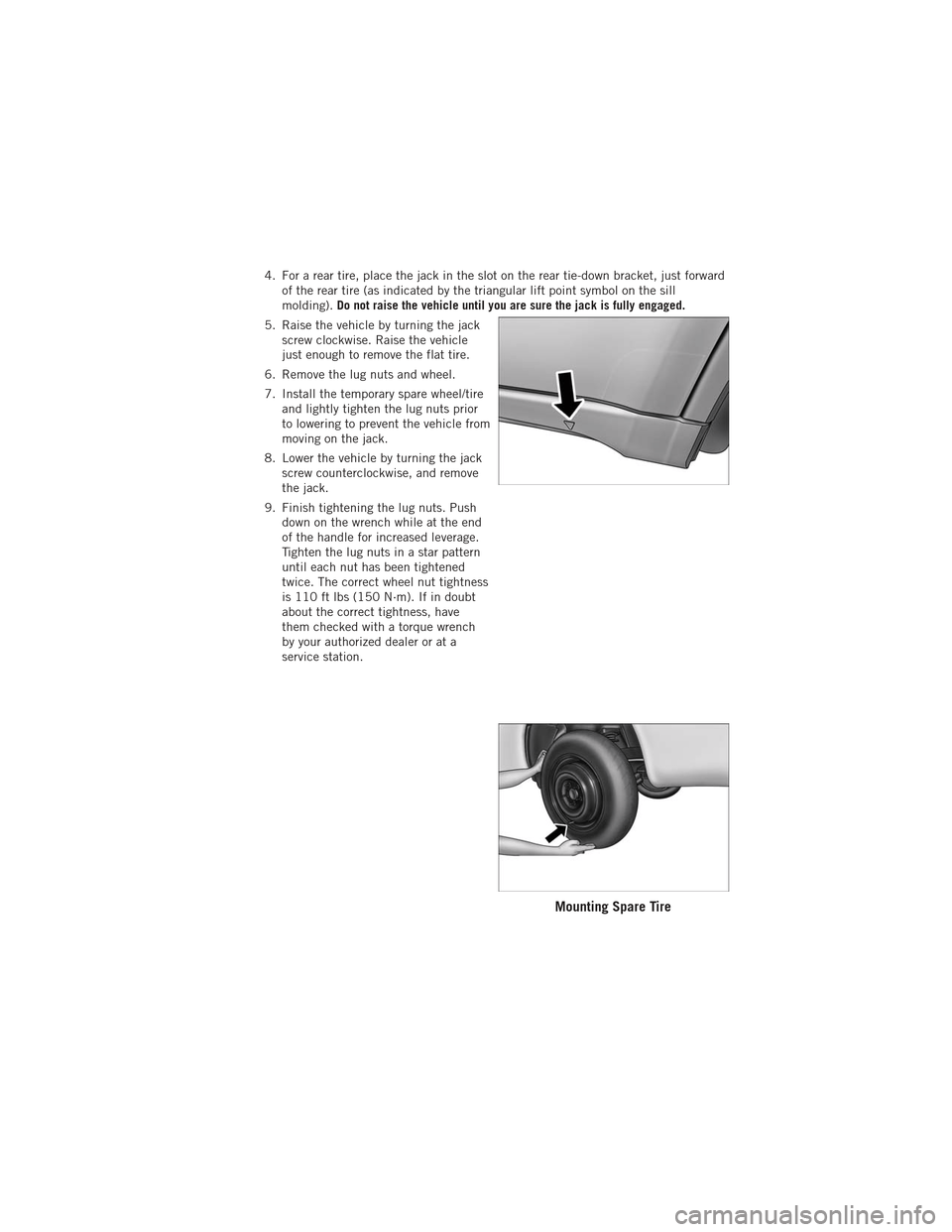
4. For a rear tire, place the jack in the slot on the rear tie-down bracket, just forwardof the rear tire (as indicated by the triangular lift point symbol on the sill
molding). Do not raise the vehicle until you are sure the jack is fully engaged.
5. Raise the vehicle by turning the jack screw clockwise. Raise the vehicle
just enough to remove the flat tire.
6. Remove the lug nuts and wheel.
7. Install the temporary spare wheel/tire and lightly tighten the lug nuts prior
to lowering to prevent the vehicle from
moving on the jack.
8. Lower the vehicle by turning the jack screw counterclockwise, and remove
the jack.
9. Finish tightening the lug nuts. Push down on the wrench while at the end
of the handle for increased leverage.
Tighten the lug nuts in a star pattern
until each nut has been tightened
twice. The correct wheel nut tightness
is 110 ft lbs (150 N·m). If in doubt
about the correct tightness, have
them checked with a torque wrench
by your authorized dealer or at a
service station.
Mounting Spare Tire
WHAT TO DO IN EMERGENCIES
99
Page 102 of 140
10. Remove the Dodge center cap using a jack tool from inside the aluminum roadwheel and snap on the protective plastic plate.
NOTE: The plastic plate will prevent the road wheel from being scratched when sliding
it under the vehicle.
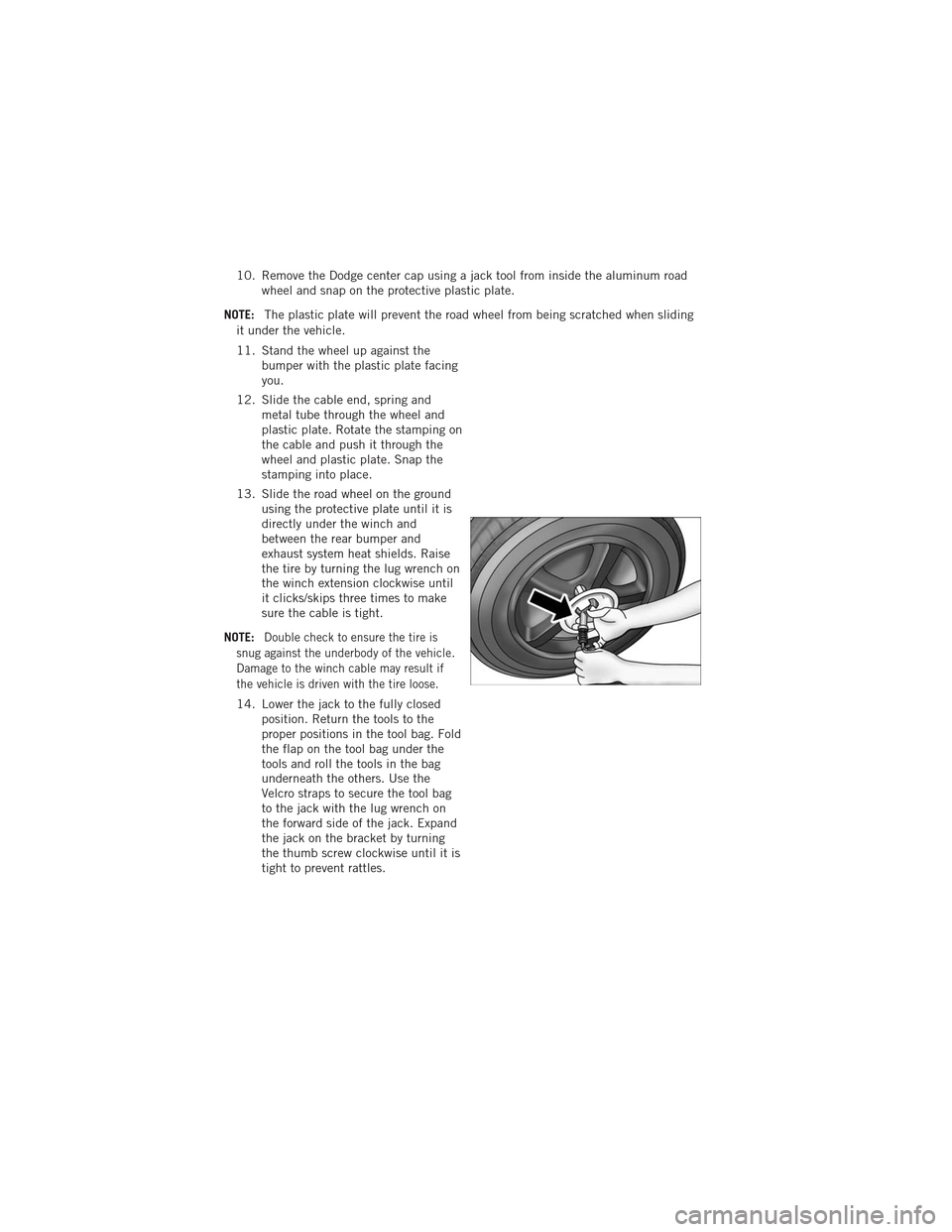
11. Stand the wheel up against the bumper with the plastic plate facing
you.
12. Slide the cable end, spring and metal tube through the wheel and
plastic plate. Rotate the stamping on
the cable and push it through the
wheel and plastic plate. Snap the
stamping into place.
13. Slide the road wheel on the ground using the protective plate until it is
directly under the winch and
between the rear bumper and
exhaust system heat shields. Raise
the tire by turning the lug wrench on
the winch extension clockwise until
it clicks/skips three times to make
sure the cable is tight.
NOTE:
Double check to ensure the tire is
snug against the underbody of the vehicle.
Damage to the winch cable may result if
the vehicle is driven with the tire loose.
14. Lower the jack to the fully closed position. Return the tools to the
proper positions in the tool bag. Fold
the flap on the tool bag under the
tools and roll the tools in the bag
underneath the others. Use the
Velcro straps to secure the tool bag
to the jack with the lug wrench on
the forward side of the jack. Expand
the jack on the bracket by turning
the thumb screw clockwise until it is
tight to prevent rattles.
WHAT TO DO IN EMERGENCIES
100
Page 103 of 140
15. Reinstall the plastic plug into the floor of the cargo area. Roll up and store theJack, Tool Kit and Tire Changing Instructions. Reinstall the cover for the jack in
the rear storage bin.
NOTE: The plastic thumb screw being on the right and the position of the lug wrench
before the velcro straps go around the fully closed jack.
16. Remove the blocks/rocks from the opposite tire.
17. Have the aluminum road wheel and tire repaired as soon as possible and
properly secure the spare tire, jack
and tool kit.
Road Tire Installation
1. Mount the road tire on the axle.
2. Install the remaining lug nuts with thecone shaped end of the nut toward
the wheel. Lightly tighten the lug
nuts.
3. Lower the vehicle to the ground by turning the jack handle
counterclockwise.
4. Finish tightening the lug nuts. Push down on the wrench while at the end of the handle for increased leverage. Tighten the lug nuts in a star pattern until each nut
has been tightened twice. The correct tightness of each lug nut is 110 ft/lbs
(150 N·m). If in doubt about the correct tightness, have them checked with a
torque wrench by your authorized dealer or service station.
5. After 25 miles (40 km) check the lug nut torque with a torque wrench to ensure that all lug nuts are properly seated against the wheel.
CAUTION!
• Do not use power tools to winch the tire up or down. Impact type tools candamage the winch mechanism.
• Do not attempt to raise the vehicle by jacking on locations other than those indicated in the Jacking Instructions for this vehicle.
• Be sure to mount the spare tire with the valve stem facing outward. The vehicle could be damaged if the spare tire is mounted incorrectly.
WHAT TO DO IN EMERGENCIES
101
Page 128 of 140
Adaptive Cruise Control (ACC) (Cruise
Control)................. 30
Air Conditioning ............ 35
Airbag .................. 15
AirbagLight ............... 92
Alarm, Panic ............... 8
All Wheel Drive (AWD) ......... 83
Anti-Lock Brake System (ABS) .... 91
Arming Theft System
(Security Alarm) ............ 14
Audio Settings . . . 42,43,44,46,49,58
Automatic Dimming Mirror ...... 29
Automatic Headlights ......... 27
Automatic Temperature
Control (ATC) .............. 35
Air Recirculation ........... 35
Automatic Operation ........ 35
Rear Temperature Control ...... 35
SYNC Temperature Button ..... 36
Automatic Transmission FluidType .............. 113
Auxiliary Audio/Video Input Jacks . . 75
AxleFluid ............ 113,114
Back-UpCamera ............ 37
Battery Charging System Light ....... 91
Belts, Seat ............... 14
Blind Spot Monitoring ......... 37
BrakeFluid ........... 113,114
Brake System WarningLight ............ 90
Break-In Recommendations,
New Vehicle ............... 27
Bulb Replacement .......... 122
Button, Start/Stop Removal ..... 8,12
Calibration, Compass ......... 76
Cargo Compartment Luggage Carrier ........... 85
Change Oil Indicator .......... 92
Changing A Flat Tire .......... 94
Charging System Light ......... 91
Check Engine Light (Malfunction
Indicator Light) ............. 90
Child Restraint ............. 16
Child Restraint Tether Anchors .... 16
ClimateControl ............. 35 Clock Setting
........ 42,44,47,55
Compass Calibration .......... 76
Cooling System Coolant Capacity .......... 113
Cruise Control (Speed Control) .... 30
CruiseLight ............... 30
Customer Assistance ......... 123
Defects, Reporting .......... 124
Dimmer Control ............. 28
Dimmer Switch, Headlight ...... 28
Disarming, Theft System ....... 14
E-85Fuel ............... 114
ECO ................... 76
Electronic Range Select (ERS) .... 34
Electronic Speed Control
(CruiseControl) ............. 30
Electronic Stability Control (ESC) . . 91
Electronic Throttle Control
WarningLight .............. 91
Electronic Vehicle Information Center
(EVIC) ................ 76,77
Electronically Shifted Transfer
Case ................... 83
Electronics Your Vehicle's Sound System .... 40
Emergency Key .............. 8
Emergency, In Case of Jacking ................ 94
Overheating ............. 92
Engine Break-In Recommendations .... 27
Compartment ............
111
Coolant (Antifreeze) ........ 113
Malfunction Indicator
(CheckEngine) ............ 90
Oil .................. 113
Oil Filter .............. 113
Oil Selection ............ 113
Overheating ............. 92
Starting ................ 13
Stopping ............... 13
EventDataRecorder ......... 108
Exterior Lights ............ 122
Flexible Fuel Vehicles ........ 114
INDEX
126