warning DODGE DURANGO 2013 3.G Owner's Manual
[x] Cancel search | Manufacturer: DODGE, Model Year: 2013, Model line: DURANGO, Model: DODGE DURANGO 2013 3.GPages: 140, PDF Size: 4.38 MB
Page 25 of 140
CAUTION!
Do not place any article under a power seat or impede its ability to move as it may cause
damage to the seat controls. Seat travel may become limited if movement is stopped by
an obstruction in the seat's path.
WARNING!
• Adjusting a seat while the vehicle is moving is dangerous. The sudden movement ofthe seat could cause you to lose control. The seat belt might not be properly adjusted,
and you could be severely injured or killed. Only adjust a seat while the vehicle is
parked.
• Do not ride with the seatback reclined so that the seat belt is no longer resting
against your chest. In a collision, you could slide under the seat belt and be severely
injured or killed. Use the recliner only when the vehicle is parked.
REAR SEATS
60/40 Split Rear Seat
Fold and Tumble
• The left or right side of the second rowseatback can folded flat to carry cargo.
The left and right side of the second row
seat can also be tumbled forward to allow
access to the third row seat.
• Pull upward on the release lever to release the seat.
NOTE:
Also, pulling upward on this handle allows the
outboard seating positions to be reclined.
• Tumble the seat forward using the red pull strap located behind the seatback.
GETTING STARTED
23
Page 27 of 140
50/50 Third Row Folding Seat
•
Either or both third row seats can be folded forward to increase the rear cargo storage area.
• After opening the liftgate, either seat can be folded flat by pulling up the release handleon the back of the seat.
• A seat that is folded flat can be returned to the upright position by using the pull strap located on the back of the seat next to the release handle.
NOTE:
The second row seats must be in their full upright position, or tumbled when folding the
third row seats.
• To raise the seat, pull the seat toward you using the strap located on the back of the seat.
WARNING!
Do not drive the vehicle with the second row seats in the tumbled position. The second
row seats are only intended to be tumbled for entry and exit to the third row seat. Failure
to follow these instructions could result in personal injury.
POWER FOLDING THIRD ROW HEAD RESTRAINTS
•For improved visibility, the third row head
restraints can be folded using a switch, lo-
cated on the instrument panels switch bank.
NOTE:
The head restraints can only be folded
downward using the power folding switch.
The head restraints must be raised manually
when occupying the third row.
GETTING STARTED
25
Page 29 of 140
WARNING!
• Persons who are unable to feel pain to the skin because of advanced age, chronicillness, diabetes, spinal cord injury, medication, alcohol use, exhaustion or other
physical conditions must exercise care when using the seat heater. It may cause
burns even at low temperatures, especially if used for long periods of time.
• Do not place anything on the seat that insulates against heat, such as a blanket or
cushion. This may cause the seat heater to overheat. Sitting in a seat that has been
overheated could cause serious burns due to the increased surface temperature of
the seat.
HEATED STEERING WHEEL
• The steering wheel contains a heating el-ement that heats the steering wheel to
one temperature setting.
• The heated steering wheel switch is lo- cated on the center instrument panel be-
low the climate controls.
• Press the switch once to turn the heating element On. Press the switch a second
time to turn the heating element Off.
• Once the heated steering wheel has been turned on, it will operate for approxi-
mately 58 to 70 minutes before automatically shutting off. The heated steering wheel
can shut off early or may not turn on when the steering wheel is already warm.
TILT/TELESCOPING STEERING COLUMN
Manual - Tilt/Telescoping Steering Column
• The tilt/telescoping control handle is lo-cated below the steering wheel at the end
of the steering column.
• Push the handle down to unlock the steer- ing column.
• To tilt the steering column, move the steering wheel upward or downward as
desired. To lengthen or shorten the steer-
ing column, pull the steering wheel out-
ward or push it inward as desired.
• Pull up on the handle to lock the column firmly in place.
GETTING STARTED
27
Page 30 of 140
Power - Tilt/Telescoping Steering Column
• The power tilt/telescoping steering con-trol is located below the turn signal/
wiper/washer/high beam lever on the
steering column.
•
To tilt the steering column, move the power
tilt/telescoping control up or down as de-
sired. To lengthen or shorten the steering
column, pull the control toward you or push
the control away from you as desired.
WARNING!
• Do not adjust the steering wheel while driving. The tilt/telescoping adjustment must
be locked while driving. Adjusting the steering wheel while driving or driving without
the tilt/telescoping adjustment locked could cause the driver to lose control of the
vehicle. Failure to follow this warning may result in you and others being severely
injured or killed.
• Moving the steering column while the vehicle is moving is dangerous. Without a
stable steering column, you could lose control of the vehicle and have a collision.
Adjust the column only while the vehicle is stopped.
GETTING STARTED
28
Page 36 of 140
Forward Collision Warning
• The Forward Collision Warning (FCW) system provides the driver with audible and visualwarnings (within the EVIC) when it detects a potential frontal collision. The warnings are
intended to provide the driver with enough time to react and avoid the potential collision.
Changing FCW Status
• The FCW feature has three settings and can be changed within the Electronic Vehicle Information Center (EVIC):
•Far
• Near
• Off
NOTE:
The FCW settings can only be changed when the vehicle is in PARK.
Far
• The default status of FCW is the “Far” setting.
• The far setting provides warnings for potential collisions more distant in front of the vehicle, allowing the driver to have the most reaction time to avoid a collision.
• This setting is designed to provide early warnings per NHTSA (National Highway Traffic Safety Administration) recommendations.
• More cautious drivers that do not mind frequent warnings may prefer this setting.
NOTE:
This setting gives you the most reaction time.
Near
• Changing the FCW status to the “Near” setting, allows the system to warn you of a potential frontal collision when you are much closer.
• This setting provides less reaction time than the “Far” setting, which allows for a more dynamic driving experience.
• More dynamic or aggressive drivers that want to avoid frequent warnings may prefer this setting.
Off
• Changing the FCW status to “Off” prevents the system from warning you of a potential frontal collision.
NOTE:
• If FCW is set to “Off”, “FCW OFF” will be displayed in the EVIC.
• Refer to the Owner's Manual on the DVD for further details.
OPERATING YOUR VEHICLE
34
Page 37 of 140
WARNING!
• Leaving the Electronic or Adaptive Speed Control system on when not in use isdangerous. You could accidentally set the system or cause it to go faster than you
want. You could lose control and have a collision. Always leave the Electronic or
Adaptive Speed Control system off when you are not using it.
• Electronic Speed Control can be dangerous where the system cannot maintain a constant speed. Your vehicle could go too fast for the conditions, and you could lose
control. A collision could be the result. Do not use Electronic Speed Control in heavy
traffic or on roads that are winding, icy, snow-covered or slippery.
• Adaptive Cruise Control (ACC) is a convenience system. It is not a substitute for active driving involvement. Pay attention to road, traffic, and weather conditions,
vehicle speed, distance to the vehicle ahead, and brake operation to ensure safe
operation of the vehicle under all road conditions. Your attention is always required
while driving to maintain safe control of your vehicle. Failure to follow these warnings
can result in a collision or serious personal injury.
The ACC system:
• Does not react to pedestrians, oncoming vehicles, and stationary objects (i.e., a
stopped vehicle in a traffic jam or a disabled vehicle).
• Cannot take street, traffic, and weather conditions into account, and may be limited
upon adverse sight distance conditions.
• Does not predict the lane curvature or the movement of preceding vehicles and will
not compensate for such changes.
• Does not always fully recognize complex driving conditions, which can result in
wrong or missing distance warnings.
• Can only apply a maximum of 25% of the vehicle’s braking capability, and will not
bring the vehicle to a complete stop.
You should switch off the ACC system:
• When driving in fog, heavy rain, heavy snow, sleet, heavy traffic, and complex driving
situations (i.e., in highway construction zones).
• When entering a turn lane or highway off ramp; when driving on roads that are
winding, icy, snow-covered, slippery, or have steep uphill or downhill slopes; and
when towing a trailer.
• When circumstances do not allow safe driving at a constant speed.
• Failure to follow these warnings can result in a collision.
• Forward Collision Warning (FCW) is not intended to avoid a collision on its own. The
driver has the responsibility to avoid a collision by controlling the vehicle via braking
and steering. Failure to follow this warning could lead to serious injury or death.
OPERATING YOUR VEHICLE
35
Page 40 of 140
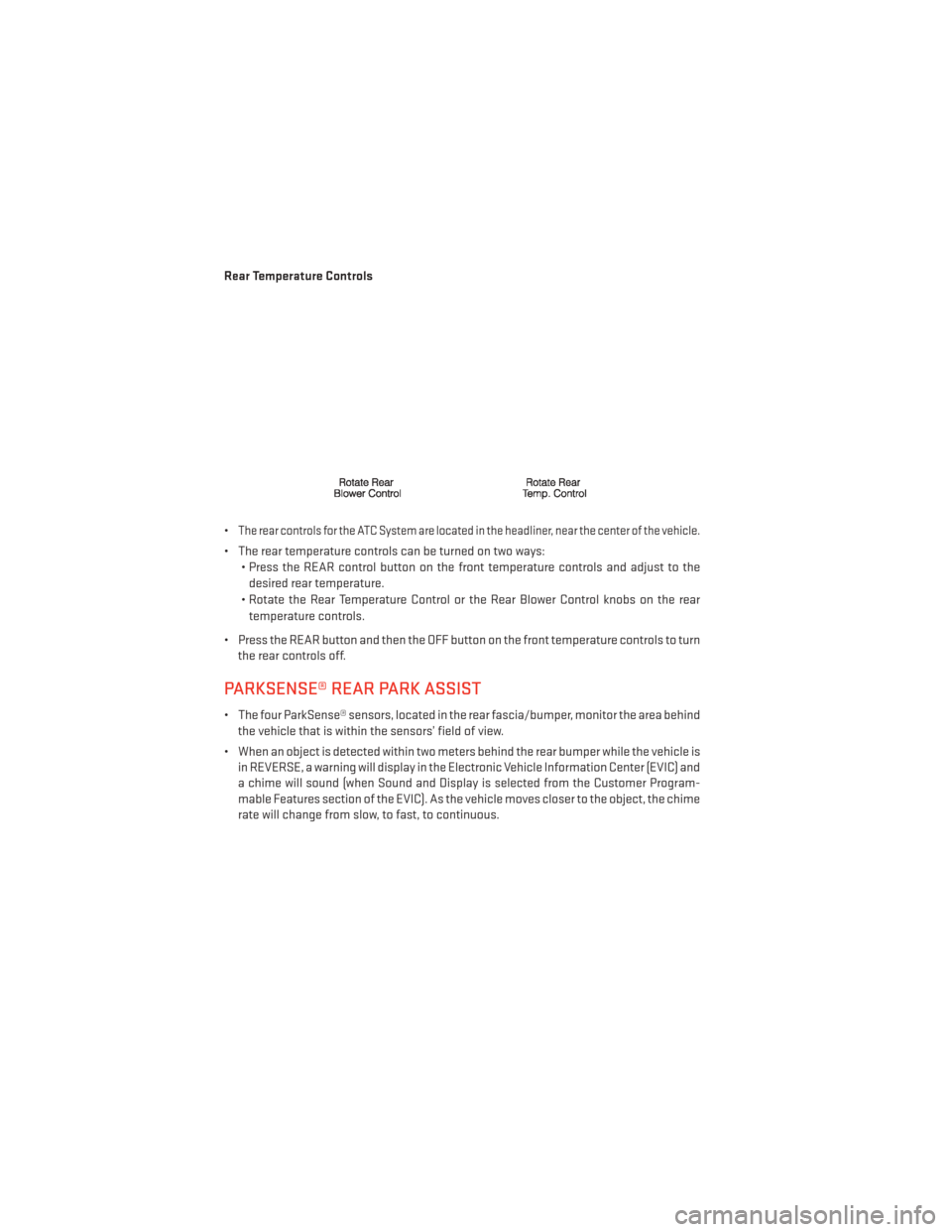
Rear Temperature Controls
•
The rear controls for the ATC System are located in the headliner, near the center of the vehicle.
• The rear temperature controls can be turned on two ways:• Press the REAR control button on the front temperature controls and adjust to the
desired rear temperature.
• Rotate the Rear Temperature Control or the Rear Blower Control knobs on the rear temperature controls.
• Press the REAR button and then the OFF button on the front temperature controls to turn the rear controls off.
PARKSENSE® REAR PARK ASSIST
• The four ParkSense® sensors, located in the rear fascia/bumper, monitor the area behindthe vehicle that is within the sensors’ field of view.
• When an object is detected within two meters behind the rear bumper while the vehicle is in REVERSE, a warning will display in the Electronic Vehicle Information Center (EVIC) and
a chime will sound (when Sound and Display is selected from the Customer Program-
mable Features section of the EVIC). As the vehicle moves closer to the object, the chime
rate will change from slow, to fast, to continuous.
OPERATING YOUR VEHICLE
38
Page 41 of 140
Cleaning the ParkSense® Sensors
• If “CLEAN PARK ASSIST SENSORS” appears in the Electronic Vehicle Information Center(EVIC), clean the ParkSense® sensors with water, car wash soap and a soft cloth. Do not
use rough or hard cloths. Do not scratch or poke the sensors. Otherwise, you could
damage the sensors.
NOTE:
When the Instrument Cluster reads either Clean Sensor or Blinded, please clean off the
bumper sensors to see if the condition is corrected.
PARKVIEW® REAR BACK-UP CAMERA
• You can see an on-screen image of the rear of your vehicle whenever the shift lever is put into REVERSE. The ParkView® Rear Back-Up Camera image will be displayed on the radio
display screen, located on the center stack of the instrument panel.
• If the radio display screen appears foggy, clean the camera lens located on the liftgate.
WARNING!
Drivers must be careful when backing up; even when using the ParkView® Rear Back-Up
Camera. Always check carefully behind your vehicle, and be sure to check for pedestrians,
animals, other vehicles, obstructions, or blind spots before backing up. You must continue
to pay attention while backing up. Failure to do so can result in serious injury or death.
BLIND SPOT MONITORING
• The Blind Spot Monitoring (BSM) system uses two radar-based sensors, located inside the rear bumper fascia, to detect Highway licensable vehicles (automobiles, trucks,
motorcycles etc.) that enter the blind spot zones from the rear/front/side of the vehicle.
• The Blind Spot Monitoring (BSM) system warning light, located in the outside mirrors, will illuminate if a vehicle moves into a blind spot zone.
• The BSM system can also be configured to sound an audible (chime) alert and mute the radio to notify you of objects that have entered the detection zones.
• Refer to your owner's manual on the DVD for further details.
OPERATING YOUR VEHICLE
39
Page 43 of 140
WARNING!
• Never leave children unattended in a vehicle, and do not leave the key in the ignitionswitch (or leave the ignition of a vehicle equipped with Keyless Enter-N-Go™ in the
ACC or ON/Run position). Occupants, particularly unattended children, can become
entrapped by the power sunroof while operating the power sunroof switch. Such
entrapment may result in serious injury or death.
• In a collision, there is a greater risk of being thrown from a vehicle with an open
sunroof. You could also be severely injured or killed. Always fasten your seat belt
properly and make sure all passengers are properly secured.
• Do not allow small children to operate the sunroof. Never allow your fingers, other
body parts, or any object to project through the sunroof opening. Injury may result.
WIND BUFFETING
• Wind buffeting can be described as a helicopter-type percussion sound. If buffetingoccurs with the rear windows open, adjust the front and rear windows together.
• If buffeting occurs with the sunroof open, adjust the sunroof opening, or adjust any window. This will minimize buffeting.
OPERATING YOUR VEHICLE
41
Page 75 of 140
•Touch-Screen Radios:To hear audio from devices connected to the USB port, press the
“MEDIA” hard-key, then touch the “AUX” or “iPod®” soft-key.
• When connected to this feature: • The iPod® can be controlled using the
radio buttons to Play, Browse, and List
the iPod® or external devices contents.
•
The iPod® battery charges when plugged
into the USB port (if supported by the spe-
cific audio device).
• Compatible iPod® devices may also be
controllable using voice commands.
Refer to the Owner's Manual on the DVD for details.
NOTE:
The USB port supports certain Mini, Classic, Nano, Touch, and iPhone® devices. The USB
port also supports playing music from compatible external USB Mass Storage Class
memory devices. For supported audio file formats, refer to the USB Port section in the
Owner's Manual on the DVD. Refer to www.UconnectPhone.com website for a list of tested
iPod®s. Some iPod® software versions may not fully support the USB port features. Please
visit Apple’s website for iPod® software updates.
Second Row USB Charging Port
• The second row USB connector port can be used for charging purposes only. Use the connection cable to connect an iPod® or external USB device to the vehicle's USB
charging port which is located in the second row center console.
NOTE:
If the device battery to be charged is com-
pletely depleted, it may take awhile to charge.
WARNING!
Do not plug in or remove the iPod® or external device while driving. Failure to follow this
warning could result in a collision.
ELECTRONICS
73