climate control DODGE DURANGO 2013 3.G User Guide
[x] Cancel search | Manufacturer: DODGE, Model Year: 2013, Model line: DURANGO, Model: DODGE DURANGO 2013 3.GPages: 140, PDF Size: 4.38 MB
Page 9 of 140
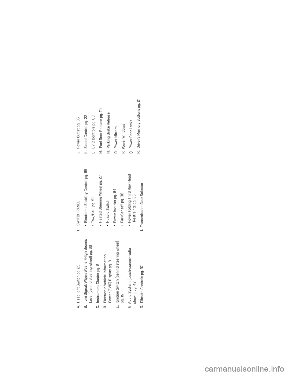
A. Headlight Switch pg. 29
B. Turn Signal/Wiper/Washer/High BeamsLever (behind steering wheel) pg. 30
C. Instrument Cluster pg. 8
D. Electronic Vehicle Information Center (EVIC) Display pg. 8
E. Ignition Switch (behind steering wheel) pg. 15
F. Audio System (touch-screen-radio shown) pg. 42
G. Climate Controls pg. 37 H. SWITCH PANEL
• Electronic Stability Control pg. 95
• Tow/Haul pg. 91
• Heated Steering Wheel pg. 27
• Hazard Switch
• Power Inverter pg. 84
• ParkSense® pg. 38
• Power Folding Third Row HeadRestraints pg. 25
I. Transmission Gear Selector J. Power Outlet pg. 85
K. Speed Control pg. 32
L. EVIC Controls pg. 80
M. Fuel Door Release pg. 114
N. Parking Brake Release
O. Power Mirrors
P. Power Windows
Q. Power Door Locks
R. Driver's Memory Buttons pg. 21
CONTROLS AT A GLANCE
7
Page 28 of 140
HEATED/VENTILATED SEATS
Front Heated Seats
• The controls for front heated seats arelocated in the climate controls near the
center of the instrument panel.
• Press the switch once to select High-level heating. Press the switch a second time
to select Low-level heating. Press the
switch a third time to shut the heating
elements Off.
• If the High-level setting is selected, the system will automatically switch to Low-
level after approximately 55 minutes. The
Low-level setting will turn Off automati-
cally after approximately 45 minutes.
Front Ventilated Seats
• Located in the seat cushion and seatback are small fans that draw the air from the passenger compartment and blow air through fine perforations in the seat cover to help
keep the driver and front passenger cooler in higher ambient temperatures.
• The ventilated seat switches are located in the climate controls near the center of the instrument panel. Press the switch once to select High speed. Press the switch a second
time to select Low speed. Press the switch a third time to turn the fans Off.
Rear Heated Seats
• Second row heated seat switches are lo- cated on the rear of the center console.
• Press the switch once to select High-level heating. Press the switch a second time
to select Low-level heating. Press the
switch a third time to shut the heating
elements Off.
• If the High-level setting is selected, the system will automatically switch to Low-
level after approximately 55 minutes. The
Low-level setting will turn Off automati-
cally after approximately 45 minutes.
GETTING STARTED
26
Page 29 of 140
WARNING!
• Persons who are unable to feel pain to the skin because of advanced age, chronicillness, diabetes, spinal cord injury, medication, alcohol use, exhaustion or other
physical conditions must exercise care when using the seat heater. It may cause
burns even at low temperatures, especially if used for long periods of time.
• Do not place anything on the seat that insulates against heat, such as a blanket or
cushion. This may cause the seat heater to overheat. Sitting in a seat that has been
overheated could cause serious burns due to the increased surface temperature of
the seat.
HEATED STEERING WHEEL
• The steering wheel contains a heating el-ement that heats the steering wheel to
one temperature setting.
• The heated steering wheel switch is lo- cated on the center instrument panel be-
low the climate controls.
• Press the switch once to turn the heating element On. Press the switch a second
time to turn the heating element Off.
• Once the heated steering wheel has been turned on, it will operate for approxi-
mately 58 to 70 minutes before automatically shutting off. The heated steering wheel
can shut off early or may not turn on when the steering wheel is already warm.
TILT/TELESCOPING STEERING COLUMN
Manual - Tilt/Telescoping Steering Column
• The tilt/telescoping control handle is lo-cated below the steering wheel at the end
of the steering column.
• Push the handle down to unlock the steer- ing column.
• To tilt the steering column, move the steering wheel upward or downward as
desired. To lengthen or shorten the steer-
ing column, pull the steering wheel out-
ward or push it inward as desired.
• Pull up on the handle to lock the column firmly in place.
GETTING STARTED
27
Page 97 of 140
- Electronic Stability Control (ESC) Activation/Malfunction Indicator Light
• If the “ESC Activation/Malfunction Indicator Light” comes on continuously with the engine running, a malfunction has been detected in the ESC system. If this light remains
on after several ignition cycles, and the vehicle has been driven several miles (kilome-
ters) at speeds greater than 30 mph (48 km/h), we recommend you drive to the nearest
service center and have the vehicle serviced immediately.
•
The “ESC Activation/Malfunction Indicator Light” starts to flash as soon as the tires lose
traction and the ESC system becomes active. If the light begins to flash during acceleration,
ease up on the accelerator and apply as little throttle as possible. Be sure to adapt your
speed and driving to the prevailing road conditions. The light also flashes when TCS is
active. To improve the vehicle's traction when starting off in deep snow, sand or gravel, it
may be desirable to switch the ESC system to Partial Off mode by momentarily pressing the
ESC Off
switch located below the climate controls, on the switch panel.
- Charging System Light
•
This light shows the status of the electrical charging system. If the charging system light
remains on, it means that the vehicle is experiencing a problem with the charging system.
• We recommend you do not continue driving if the charging system light is on. Have the vehicle serviced immediately.
- Oil Pressure Warning Light
• This light indicates low engine oil pressure. If the light turns on while driving, stop the vehicle and shut off the engine as soon as possible. A chime will sound for four minutes
when this light turns on.
• We recommend you do not operate the vehicle or engine damage will occur. Have the vehicle serviced immediately.
- Anti-Lock Brake (ABS) Light
• This light monitors the Anti-Lock Brake System (ABS).
• If the light is not on during starting, stays on, or turns on while driving, we recommend you drive to the nearest service center and have the vehicle serviced immediately.
- Electronic Throttle Control (ETC) Light
• This light informs you of a problem with the Electronic Throttle Control (ETC) system.
• If a problem is detected, the light will come on while the engine is running. Cycle the ignition key when the vehicle has completely stopped and the shift lever is placed in the
PARK position; the light should turn off.
• If the light remains lit with the engine running, your vehicle will usually be drivable; however, see an authorized service center immediately. If the light is flashing when the
engine is running, immediate service is required and you may experience reduced
performance, an elevated/rough idle or engine stall and your vehicle may require towing.
- Air Bag Warning Light
• If the light is not on during starting, stays on, or turns on while driving, have the vehicle serviced by an authorized service center immediately.
WHAT TO DO IN EMERGENCIES
95
Page 127 of 140
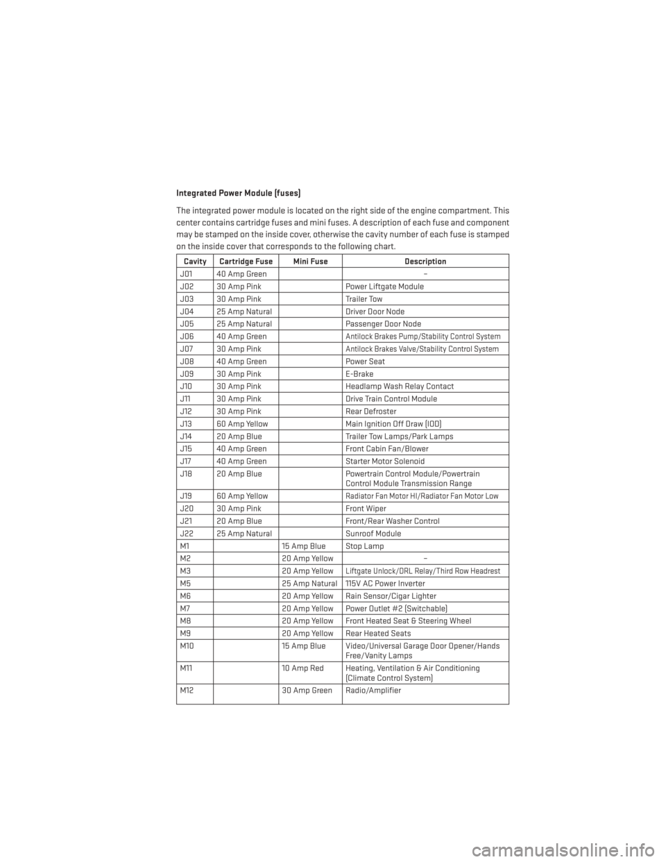
Integrated Power Module (fuses)
The integrated power module is located on the right side of the engine compartment. This
center contains cartridge fuses and mini fuses. A description of each fuse and component
may be stamped on the inside cover, otherwise the cavity number of each fuse is stamped
on the inside cover that corresponds to the following chart.
Cavity Cartridge Fuse Mini FuseDescription
J01 40 Amp Green –
J02 30 Amp Pink Power Liftgate Module
J03 30 Amp Pink Trailer Tow
J04 25 Amp Natural Driver Door Node
J05 25 Amp Natural Passenger Door Node
J06 40 Amp Green
Antilock Brakes Pump/Stability Control System
J07 30 Amp PinkAntilock Brakes Valve/Stability Control System
J08 40 Amp Green Power Seat
J09 30 Amp Pink E-Brake
J10 30 Amp Pink Headlamp Wash Relay Contact
J11 30 Amp Pink Drive Train Control Module
J12 30 Amp Pink Rear Defroster
J13 60 Amp Yellow Main Ignition Off Draw (IOD)
J14 20 Amp Blue Trailer Tow Lamps/Park Lamps
J15 40 Amp Green Front Cabin Fan/Blower
J17 40 Amp Green Starter Motor Solenoid
J18 20 Amp Blue Powertrain Control Module/Powertrain
Control Module Transmission Range
J19 60 Amp Yellow
Radiator Fan Motor HI/Radiator Fan Motor Low
J20 30 Amp Pink Front Wiper
J21 20 Amp Blue Front/Rear Washer Control
J22 25 Amp Natural Sunroof Module
M1 15 Amp Blue Stop Lamp
M2 20 Amp Yellow –
M3 20 Amp Yellow
Liftgate Unlock/DRL Relay/Third Row Headrest
M525 Amp Natural 115V AC Power Inverter
M6 20 Amp Yellow Rain Sensor/Cigar Lighter
M7 20 Amp Yellow Power Outlet #2 (Switchable)
M8 20 Amp Yellow Front Heated Seat & Steering Wheel
M9 20 Amp Yellow Rear Heated Seats
M10 15 Amp Blue Video/Universal Garage Door Opener/Hands
Free/Vanity Lamps
M11 10 Amp Red Heating, Ventilation & Air Conditioning
(Climate Control System)
M12 30 Amp Green Radio/Amplifier
MAINTAINING YOUR VEHICLE
125
Page 128 of 140
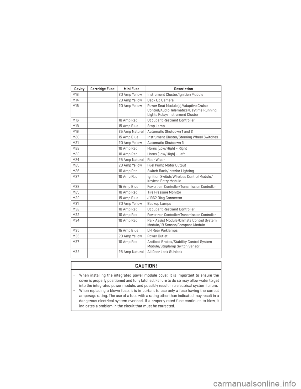
Cavity Cartridge Fuse Mini FuseDescription
M13 20 Amp Yellow Instrument Cluster/Ignition Module
M14 20 Amp Yellow Back Up Camera
M15 20 Amp Yellow Power Seat Module(s)/Adaptive Cruise
Control/Audio Telematics/Daytime Running
Lights Relay/Instrument Cluster
M16 10 Amp Red Occupant Restraint Controller
M18 15 Amp Blue Stop Lamp
M19 25 Amp Natural Automatic Shutdown 1 and 2
M20 15 Amp Blue Instrument Cluster/Steering Wheel Switches
M21 20 Amp Yellow Automatic Shutdown 3
M22 10 Amp Red Horns (Low/High) – Right
M23 10 Amp Red Horns (Low/High) – Left
M24 25 Amp Natural Rear Wiper
M25 20 Amp Yellow Fuel Pump Motor Output
M26 10 Amp Red Switch Bank/Interior Lighting
M27 10 Amp Red Ignition Switch/Wireless Control Module/
Keyless Entry Module
M28 15 Amp Blue
Powertrain Controller/Transmission Controller
M2910 Amp Red Tire Pressure Monitor
M30 15 Amp Blue J1962 Diag Connector
M31 20 Amp Yellow Backup Lamps
M32 10 Amp Red Occupant Restraint Controller
M33 10 Amp Red
Powertrain Controller/Transmission Controller
M3410 Amp Red Park Assist Module/Climate Control System
Module/IR Sensor/Compass Module
M35 15 Amp Blue LH Rear Parklamps
M36 20 Amp Yellow Power Outlet
M37 10 Amp Red Antilock Brakes/Stability Control System
Module/Stoplamp Switch Sensor
M38 25 Amp Natural All Door Lock &Unlock
CAUTION!
• When installing the integrated power module cover, it is important to ensure the
cover is properly positioned and fully latched. Failure to do so may allow water to get
into the integrated power module, and possibly result in a electrical system failure.
• When replacing a blown fuse, it is important to use only a fuse having the correct
amperage rating. The use of a fuse with a rating other than indicated may result in a
dangerous electrical system overload. If a properly rated fuse continues to blow, it
indicates a problem in the circuit that must be corrected.
MAINTAINING YOUR VEHICLE
126