tow DODGE DURANGO 2014 3.G Owner's Manual
[x] Cancel search | Manufacturer: DODGE, Model Year: 2014, Model line: DURANGO, Model: DODGE DURANGO 2014 3.GPages: 188, PDF Size: 3.8 MB
Page 114 of 188
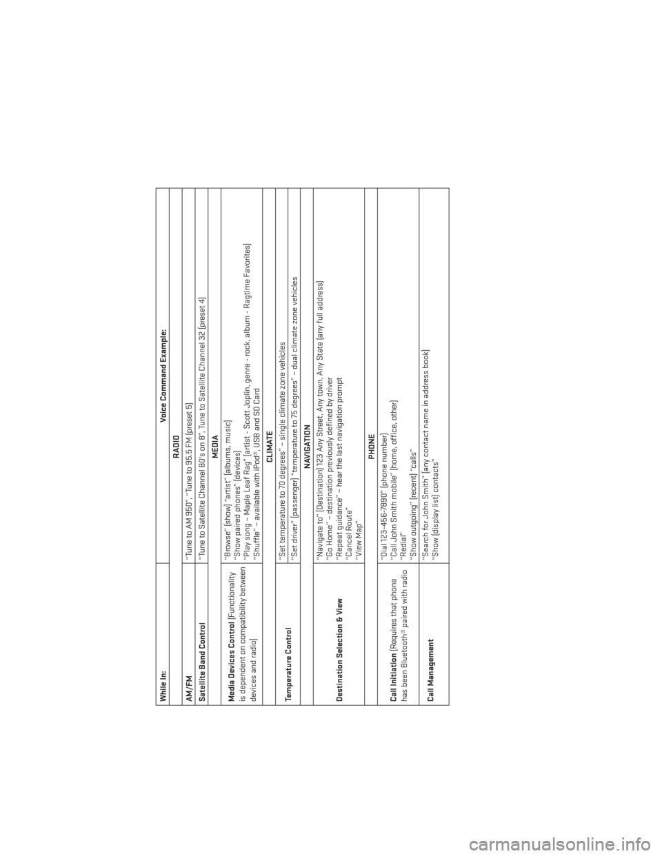
While In:Voice Command Example:
RADIO
AM/FM “Tune to AM 950”, “Tune to 95.5 FM (preset 5)
Satellite Band Control “Tune to Satellite Channel 80's on 8”, Tune to Satellite Channel 32 (preset 4)
MEDIA
Media Devices Control (Functionality
is dependent on compatibility between
devices and radio) “Browse” (show) “artist” (albums, music)
“Show paired phones” (devices)
“Play song – Maple Leaf Rag” (artist - Scott Joplin, genre - rock, album - Ragtime Favorites)
“Shuffle” – available with iPod®, USB and SD Card
CLIMATE
Temperature Control “Set temperature to 70 degrees” – single climate zone vehicles
“Set driver” (passenger) “temperature to 75 degrees” – dual climate zone vehicles
NAVIGATION
Destination Selection & View “Navigate to” (Destination) 123 Any Street, Any town, Any State (any full address)
“Go Home” – destination previously defined by driver
“Repeat guidance” – hear the last navigation prompt
“Cancel Route”
“View Map”
PHONE
Call Initiation (Requires that phone
has been Bluetooth® paired with radio “Dial 123-456-7890” (phone number)
“Call John Smith mobile” (home, office, other)
“Redial”
“Show outgoing” (recent) “calls”
Call Management “Search for John Smith” (any contact name in address book)
“Show (display list) contacts”
ELECTRONICS
112
Page 127 of 188
ROOF LUGGAGE RACK
The crossbars on your vehicle are delivered stowed within the roof rack side rails. When
installed, the roof rack can hold a maximum of 150 lbs (68 kg) of evenly distributed weight.
Installing The Crossbars
1. To install the crossbars, completely loosen the thumb screws at both ends and slide thecrossbar out from its stowed position.
2. Bend the pivot points at each end of the crossbar and push the thumb screw down.
NOTE:
Position the crossbars across the roof making sure the letters on the crossbar align with the
matching letters on the side rail.
3. Set the crossbars into position, slide them into the groove and tighten the thumb screws.
4. Refer to the Owner's Manual on the DVD for further details.
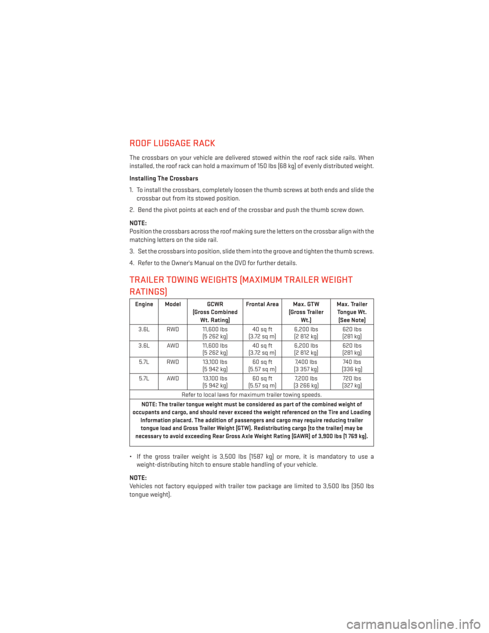
TRAILER TOWING WEIGHTS (MAXIMUM TRAILER WEIGHT
RATINGS)
Engine Model GCWR (Gross CombinedWt. Rating) Frontal Area Max. GTW
(Gross TrailerWt.) Max. Trailer
Tongue Wt. (See Note)
3.6L RWD 11,600 lbs (5 262 kg)40 sq ft
(3.72sqm) 6,200 lbs
(2 812 kg) 620 lbs
(281 kg)
3.6L AWD 11,600 lbs (5 262 kg)40 sq ft
(3.72sqm) 6,200 lbs
(2 812 kg) 620 lbs
(281 kg)
5.7L RWD 13,100 lbs (5 942 kg)60 sq ft
(5.57 sq m) 7,400 lbs
(3 357 kg) 740 lbs
(336 kg)
5.7L AWD 13,100 lbs (5 942 kg)60 sq ft
(5.57 sq m) 7,200 lbs
(3 266 kg) 720 lbs
(327 kg)
Refer to local laws for maximum trailer towing speeds.
NOTE: The trailer tongue weight must be considered as part of the combined weight of
occupants and cargo, and should never exceed the weight referenced on the Tire and Loading Information placard. The addition of passengers and cargo may require reducing trailertongue load and Gross Trailer Weight (GTW). Redistributing cargo (to the trailer) may be
necessary to avoid exceeding Rear Gross Axle Weight Rating (GAWR) of 3,900 lbs (1 769 kg).
• If the gross trailer weight is 3,500 lbs (1587 kg) or more, it is mandatory to use a weight-distributing hitch to ensure stable handling of your vehicle.
NOTE:
Vehicles not factory equipped with trailer tow package are limited to 3,500 lbs (350 lbs
tongue weight).
UTILITY
125
Page 128 of 188
RECREATIONAL TOWING (BEHIND MOTORHOME, ETC.)
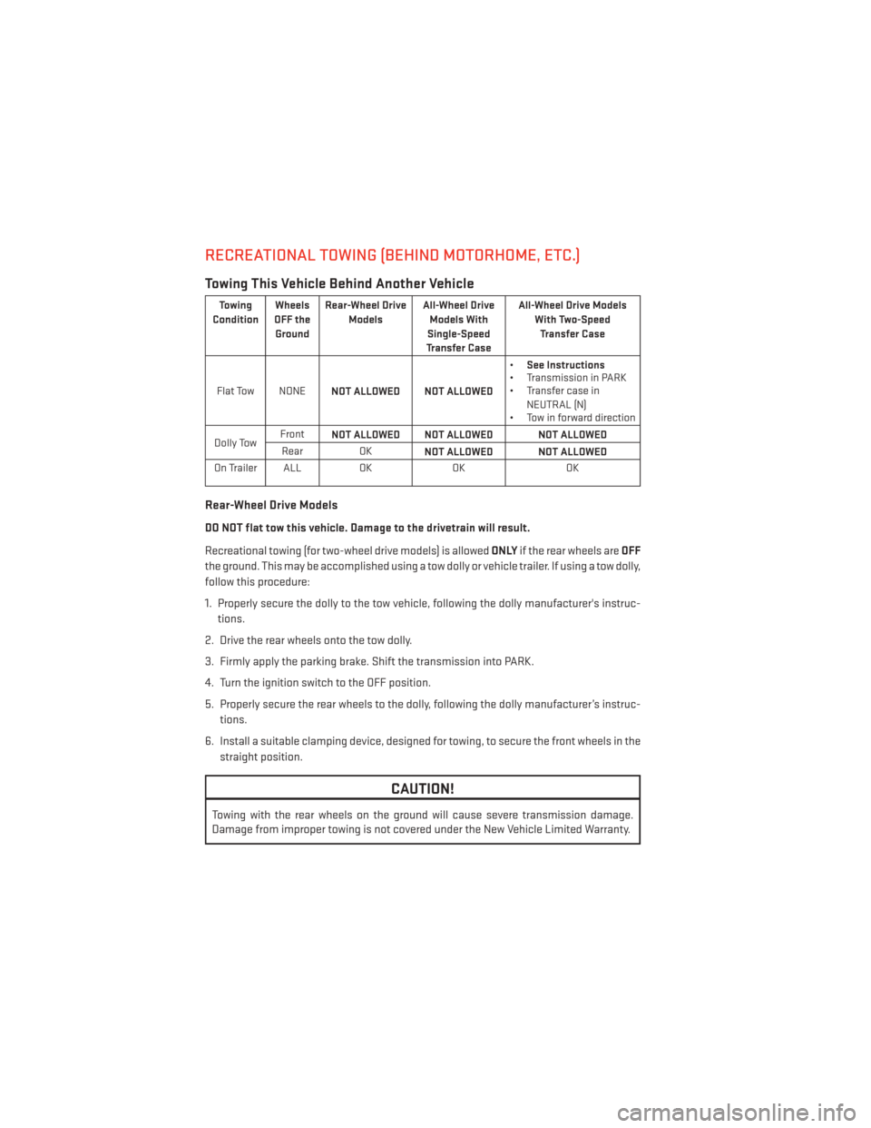
Towing This Vehicle Behind Another Vehicle
Towing
Condition Wheels
OFF the Ground Rear-Wheel Drive
Models All-Wheel Drive
Models With
Single-Speed
Transfer Case All-Wheel Drive Models
With Two-SpeedTransfer Case
Flat Tow NONE NOT ALLOWED NOT ALLOWED •
See Instructions
• Transmission in PARK
• Transfer case in
NEUTRAL (N)
• Tow in forward direction
Dolly Tow Front
NOT ALLOWED NOT ALLOWED NOT ALLOWED
Rear OK NOT ALLOWED NOT ALLOWED
On Trailer ALL OKOK OK
Rear-Wheel Drive Models
DO NOT flat tow this vehicle. Damage to the drivetrain will result.
Recreational towing (for two-wheel drive models) is allowed ONLYif the rear wheels are OFF
the ground. This may be accomplished using a tow dolly or vehicle trailer. If using a tow dolly,
follow this procedure:
1. Properly secure the dolly to the tow vehicle, following the dolly manufacturer's instruc- tions.
2. Drive the rear wheels onto the tow dolly.
3. Firmly apply the parking brake. Shift the transmission into PARK.
4. Turn the ignition switch to the OFF position.
5. Properly secure the rear wheels to the dolly, following the dolly manufacturer’s instruc- tions.
6. Install a suitable clamping device, designed for towing, to secure the front wheels in the straight position.
CAUTION!
Towing with the rear wheels on the ground will cause severe transmission damage.
Damage from improper towing is not covered under the New Vehicle Limited Warranty.
UTILITY
126
Page 129 of 188
All-Wheel Drive Models (Single-Speed Transfer Case)
Recreational towing is not allowed.This model does not have a NEUTRAL position in the
transfer case.
NOTE:
This vehicle may be towed on a flatbed or vehicle trailer provided all four wheels are OFF the
ground.
CAUTION!
Towing this vehicle in violation of the above requirements can cause severe transmis-
sion and/or transfer case damage. Damage from improper towing is not covered under
the New Vehicle Limited Warranty.
All-Wheel Drive Models (Two-Speed Transfer Case)
The transfer case must be shifted into NEUTRAL (N) and the transmission must be in PARK
for recreational towing. The NEUTRAL (N) selection button is at the center of the transfer
case selector switches. Shifts into transfer case NEUTRAL (N) can take place from any
other transfer case mode.
CAUTION!
• DO NOT dolly tow any All-Wheel Drive (AWD) vehicle. Internal damage to the trans- mission or transfer case will occur if a dolly is used when recreational towing.
• Tow only in the forward direction. Towing this vehicle backwards can cause severe
damage to the transfer case.
• The transmission must be in PARK for recreational towing.
• Before recreational towing, perform the procedure outlined under “Shifting Into
NEUTRAL(N)” to be certain that the transfer case is fully in NEUTRAL (N). Otherwise,
internal damage will result.
• Failure to follow these procedures can cause severe transmission and/or transfer
case damage. Damage from improper towing is not covered under the New Vehicle
Limited Warranty.
• Do not use a bumper-mounted clamp-on tow bar on your vehicle. The bumper face
bar will be damaged.
UTILITY
127
Page 130 of 188
Shifting Into NEUTRAL
Use the following procedure to prepare your vehicle for recreational towing:
1. Bring the vehicle to a complete stop, with the engine running.
2. Press and hold the brake pedal.
3. Shift the transmission into NEUTRAL.
4. Using a ballpoint pen or similar object, press and hold the recessed transfer caseNEUTRAL (N) button (located by the selector switch) for four seconds. The light behind
the N symbol will blink, indicating shift in progress. The light will stop blinking (stay on
solid) when the shift to NEUTRAL (N) is complete. A “FOUR WHEEL DRIVE SYSTEM IN
NEUTRAL” message will display on the EVIC (Electronic Vehicle Information Center).
5. After the shift is completed and the NEUTRAL (N) light stays on, release the NEUTRAL (N) button.
6. Shift the transmission into REVERSE.
7. Release the brake pedal for five seconds and ensure that there is no vehicle movement.
8. Shift the transmission back into NEUTRAL.
9. Firmly apply the parking brake.
10. With the transmission and transfer case in NEUTRAL, press and hold the ENGINE START/STOP button until the engine turns off. Turning the engine off will automatically
place the transmission in PARK.
11.
Press the ENGINE STOP/START button again (without pressing the brake pedal), if needed,
to turn the ignition switch to the OFF position.
CAUTION!
Damage to the transmission may occur if the transmission is shifted into PARK with the
transfer case in NEUTRAL (N) and the engine running. With the transfer case in NEUTRAL
(N) ensure that the engine is OFF before shifting the transmission into PARK.
12. Attach the vehicle to the tow vehicle using a suitable tow bar.
13. Release the parking brake.
UTILITY
128
Page 131 of 188
NOTE:
• Steps 1 through 3 are requirements that must be met before pressing the NEUTRAL (N)button, and must continue to be met until the shift has been completed. If any of these
requirements are not met before pressing the NEUTRAL (N) button or are no longer met
during the shift, the NEUTRAL (N) indicator light will flash continuously until all require-
ments are met or until the NEUTRAL (N) button is released.
• The ignition switch must be in the ON/RUN position for a shift to take place and for the position indicator lights to be operable. If the ignition switch is not in the ON/RUN
position, the shift will not take place and no position indicator lights will be on or flashing.
• A flashing NEUTRAL (N) position indicator light indicates that shift requirements have not been met.
CAUTION!
•Towing with the rear wheels on the ground will cause severe transmission damage.
Damage from improper towing is not covered under the New Vehicle Limited Warranty.
• Front or rear wheel lifts should not be used. Internal damage to the transmission or
transfer case will occur if a front or rear wheel lift is used when recreational towing.
• It is necessary to follow these steps to be certain that the transfer case is fully in NEUTRAL before recreational towing to prevent damage to internal parts.
WARNING!
You or others could be injured if you leave the vehicle unattended with the transfer case
in the NEUTRAL position without first fully engaging the parking brake. The transfer case
NEUTRAL position disengages both the front and rear driveshafts from the powertrain
and will allow the vehicle to move even if the transmission is in PARK. The parking brake
should always be applied when the driver is not in the vehicle.
UTILITY
129
Page 132 of 188
Shifting Out Of NEUTRAL (N)
Use the following procedure to prepare your vehicle for normal usage:
1. Bring the vehicle to a complete stop, leaving it connected to the tow vehicle.
2. Firmly apply the parking brake.
3. Start the engine.
4. Press and hold the brake pedal.
5. Shift the transmission into NEUTRAL.
6. Using a ballpoint pen or similar object, press and hold the recessed transfer caseNEUTRAL (N) button (located by the selector switch) for one second.
7. When the NEUTRAL (N) indicator light turns off, release the NEUTRAL (N) button.
8. After the NEUTRAL (N) button has been released, the transfer case will shift to the position indicated by the selector switch.
9. Shift the transmission into PARK and turn the engine OFF.
10. Release the brake pedal.
11. Disconnect vehicle from the tow vehicle.
12. Start the engine.
13. Press and hold the brake pedal.
14. Release the parking brake.
15. Shift the transmission into DRIVE, release the brake pedal, and check that the vehicle operates normally.
NOTE:
• Steps 1 through 5 are requirements that must be met before pressing the NEUTRAL (N) button, and must continue to be met until the shift has been completed. If any of these
requirements are not met before pressing the NEUTRAL (N) button or are no longer met
during the shift, the NEUTRAL (N) indicator light will flash continuously until all require-
ments are met or until the NEUTRAL (N) button is released.
• The ignition switch must be in the ON/RUN position for a shift to take place and for the position indicator lights to be operable. If the ignition switch is not in the ON/RUN
position, the shift will not take place and no position indicator lights will be on or flashing.
• A flashing NEUTRAL (N) position indicator light indicates that shift requirements have not been met.
UTILITY
130
Page 135 of 188
Operation of the Brake Warning Light can be checked by turning the ignition switch from the
OFF position to the ON/RUN position. The light should illuminate for approximately two
seconds. The light should then turn off unless the parking brake is applied or a brake fault
is detected. If the light does not illuminate, have the light inspected by an authorized dealer.
The light also will turn on when the parking brake is applied with the ignition switch in the
ON/RUN position.
NOTE:
This light shows only that the parking brake is applied. It does not show the degree of brake
application.
WARNING!
Driving a vehicle with the red brake light on is dangerous. Part of the brake system may
have failed. It will take longer to stop the vehicle. You could have a collision. Have the
vehicle checked immediately.
- Malfunction Indicator Light (MIL)
The Malfunction Indicator Light (MIL) is part of an onboard diagnostic system called OBD II
that monitors engine and automatic transmission control systems. The light will illuminate
when the key is in the ON/RUN position before engine start. If the bulb does not come on
when turning the key from OFF to ON/RUN, have the condition checked promptly.
Certain conditions, poor fuel quality, etc., may illuminate the light after engine start. The
vehicle should be serviced if the light stays on through several of your typical driving cycles.
In most situations, the vehicle will drive normally and will not require towing.
CAUTION!
Prolonged driving with the Malfunction Indicator Light (MIL) on could cause damage to
the engine control system. It also could affect fuel economy and driveability. If the MIL is
flashing, severe catalytic converter damage and power loss will soon occur. Immediate
service is required.
WARNING!
A malfunctioning catalytic converter, as referenced above, can reach higher tempera-
tures than in normal operating conditions. This can cause a fire if you drive slowly or park
over flammable substances such as dry plants, wood, cardboard, etc. This could result in
death or serious injury to the driver, occupants or others.
WHAT TO DO IN EMERGENCIES
133
Page 137 of 188
- Anti-Lock Brake (ABS) Light
This light monitors the Anti-Lock Brake System (ABS). The light will turn on when the ignition
switch is turned to the ON/RUN position and may stay on for as long as four seconds.
If the ABS light remains on or turns on while driving, it indicates that the Anti-Lock portion
of the brake system is not functioning and that service is required. However, the conven-
tional brake system will continue to operate normally if the BRAKE warning light is not on.
If the ABS light is on, the brake system should be serviced as soon as possible to restore the
benefits of Anti-Lock brakes. If the ABS light does not turn on when the ignition switch is
turned to the ON/RUN position, have the light inspected by an authorized dealer.
- Electronic Throttle Control (ETC) Light
This light informs you of a problem with the Electronic Throttle Control (ETC) system.
If a problem is detected, the light will come on while the engine is running. Cycle the ignition
key when the vehicle has completely stopped and the shift lever/gear selector is placed in
the PARK position; the light should turn off.
If the light remains lit with the engine running, your vehicle will usually be drivable; however,
see an authorized service center immediately. If the light is flashing when the engine is
running, immediate service is required and you may experience reduced performance, an
elevated/rough idle or engine stall and your vehicle may require towing.
- Air Bag Warning Light
This light will turn on for four to eight seconds as a bulb check when the ignition switch is
first turned to the ON/RUN position. If the light is either not on during starting, stays on, or
turns on while driving, have the system inspected at an authorized dealer as soon as
possible. Refer to “Occupant Restraints” in “Things To Know Before Starting Your Vehicle” of
your Owner’s Manual for further information.
NOTE:
The Air Bag System is designed to be maintenance free.
WHAT TO DO IN EMERGENCIES
135
Page 141 of 188
Spare Tire Stowage
• The spare tire is stowed under the rear ofthe vehicle by means of a cable winch
mechanism. To remove or stow the spare,
use the jack handle/lug wrench con-
nected to the square socket extension to
rotate the “spare tire drive” nut. The nut
is located under a plastic cover at the
center-rear of the cargo floor area, just
inside the liftgate opening.
Spare Tire Removal
1. Remove the jack tools from the bag.
2. Raise the protective rubber mat covering the storage compartment floor and remove the
plug to access the winch drive.
3. Fit the jack handle extension over the drive nut. Use the lug wrench handle and extension to completely lower the spare tire. Keep turning the handle until the winch STOPS.
NOTE:
Do not use power tools to operate the winch.
WHAT TO DO IN EMERGENCIES
139