warning light DODGE DURANGO 2014 3.G User Guide
[x] Cancel search | Manufacturer: DODGE, Model Year: 2014, Model line: DURANGO, Model: DODGE DURANGO 2014 3.GPages: 188, PDF Size: 3.8 MB
Page 3 of 188
INTRODUCTION/WELCOME
WELCOME FROM CHRYSLER GROUP LLC . . . 2
CONTROLS AT A GLANCE
DRIVER COCKPIT................6
INSTRUMENT CLUSTER .............8
GETTING STARTED
KEYFOB ....................10
REMOTE START.................11
KEYLESS ENTER-N-GO™ ............11
VEHICLE SECURITY ALARM ..........14
SEATBELT ...................15
SUPPLEMENTAL RESTRAINT SYSTEM (SRS) —
AIRBAGS ....................16
CHILD RESTRAINTS ..............17
FRONT SEATS ..................21
REARSEATS ..................24
POWER FOLDING THIRD ROW HEAD
RESTRAINTS ..................26
HEATED/VENTILATED SEATS .........26
HEATED STEERING WHEEL ..........28
TILT/TELESCOPING STEERING COLUMN . . . 29
OPERATING YOUR VEHICLE
ENGINE BREAK-IN RECOMMENDATIONS . . . 30
HEADLIGHT SWITCH ..............30
TURN SIGNAL/WIPER/WASHER/HIGH BEAM
LEVER ......................31
AUTOMATIC DIMMING MIRRORS .......33
SPEED CONTROL ................33
ADAPTIVE CRUISE CONTROL (ACC) ......35
FORWARD COLLISION WARNING (FCW)
WITHMITIGATION ...............37
ELECTRONIC SHIFTER .............39
AUTOSTICK® ..................40
FUEL ECONOMY (ECO) MODE .........41
AUTOMATIC CLIMATE CONTROLS WITH
TOUCHSCREEN .................42
PARKSENSE® REAR PARK ASSIST ......45
PARKVIEW® REAR BACK-UP CAMERA ....45
BLIND SPOT MONITORING ...........46
POWER SUNROOF ...............46
WIND BUFFETING ................47
ELECTRONICS
YOUR VEHICLE'S SOUND SYSTEM ......48
IDENTIFYING YOUR RADIO ...........50
Uconnect® ACCESS ..............51
Uconnect® 5.0 .................66
Uconnect® 8.4A .................74
Uconnect® 8.4AN ...............94
STEERING WHEEL AUDIO CONTROLS ....115
ELECTRONIC VEHICLE INFORMATION
CENTER (EVIC) .................115
PROGRAMMABLE FEATURES .........116UNIVERSAL GARAGE DOOR OPENER
(HomeLink®)
..................118
POWER INVERTER ..............120
POWER OUTLET ................121
OFF-ROAD CAPABILITIES
ALL-WHEEL DRIVE OPERATION .......123
UTILITY
ROOF LUGGAGE RACK............125
TRAILER TOWING WEIGHTS
(MAXIMUM TRAILER WEIGHT RATINGS) . . 125
RECREATIONAL TOWING
(BEHIND MOTORHOME, ETC.) ........126
WHAT TO DO IN EMERGENCIES
ROADSIDE ASSISTANCE...........131INSTRUMENT CLUSTER WARNING LIGHTS . . . 131IF YOUR ENGINE OVERHEATS .........137
JACKING AND TIRE CHANGING .......138
BATTERY LOCATION ..............147
JUMP-STARTING ...............147
MANUAL PARK RELEASE 8-SPEED .....150
TOWING A DISABLED VEHICLE ........151
FREEING A STUCK VEHICLE .........152
EVENT DATA RECORDER (EDR) ........153
CAP-LESS FUEL FILL FUNNEL ........153
MAINTAINING YOUR VEHICLE
OPENING THE HOOD.............154
ADDING FUEL .................155
ENGINE COMPARTMENT ...........157
FLUIDS AND CAPACITIES ...........159
MAINTENANCE SCHEDULE —
GASOLINE ENGINE ...............161
MAINTENANCE RECORD ...........164
FUSES .....................165
TIRE PRESSURES ...............168
WHEEL AND WHEEL TRIM CARE ......169
EXTERIOR BULBS ..............169
CUSTOMER ASSISTANCE
CHRYSLER GROUP LLC
CUSTOMER CENTER .............170
CHRYSLER CANADA INC.
CUSTOMER CENTER .............170
ASSISTANCE FOR THE HEARING IMPAIRED..170
PUBLICATIONS ORDERING ..........170
REPORTING SAFETY DEFECTS IN THE
UNITEDSTATES ................171
MOPAR® ACCESSORIES
AUTHENTIC ACCESSORIES BY MOPAR® . . . 172
FREQUENTLY ASKED QUESTIONS
FREQUENTLY ASKED QUESTIONS ......173
INDEX....................175
TABLE OF CONTENTS
Page 10 of 188
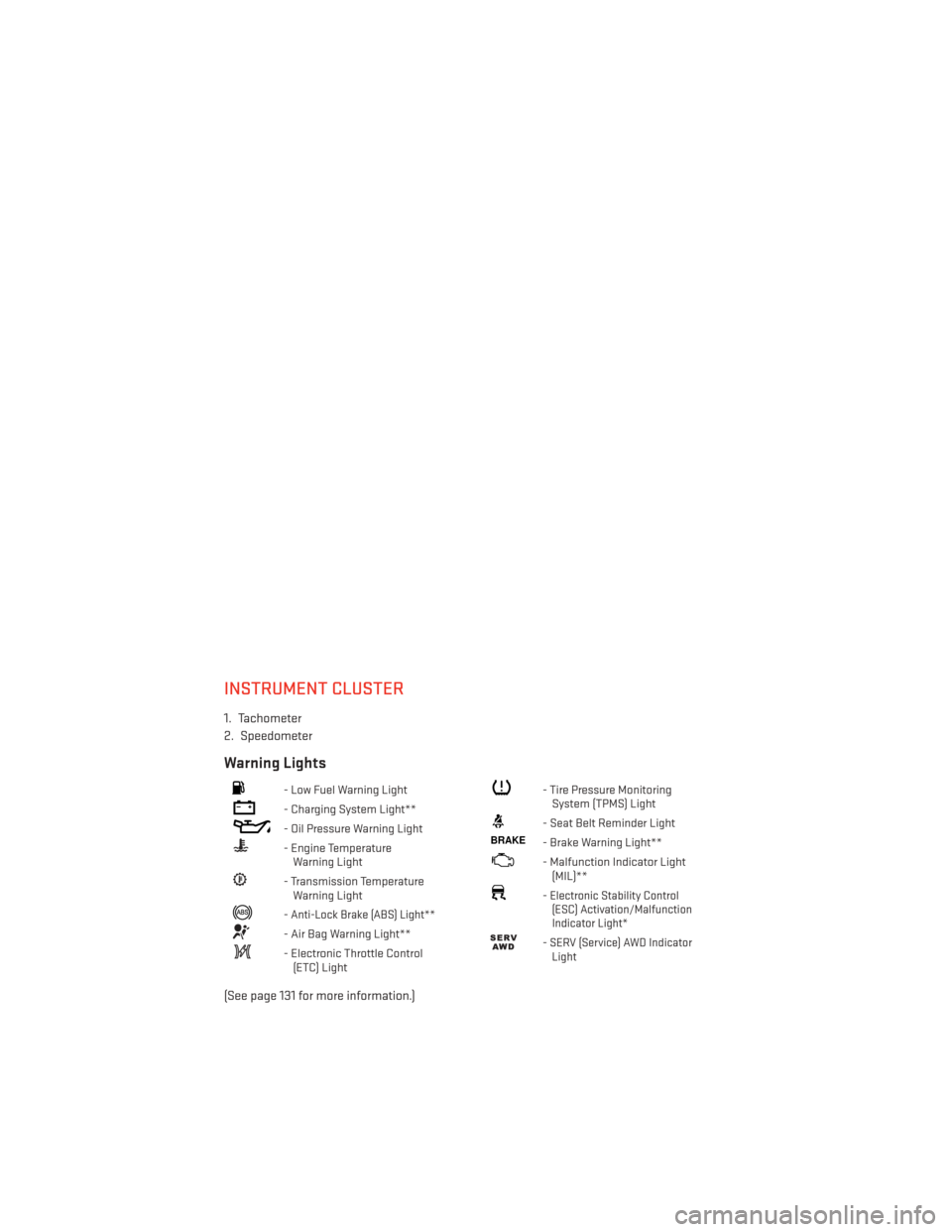
INSTRUMENT CLUSTER
1. Tachometer
2. Speedometer
Warning Lights
- Low Fuel Warning Light
- Charging System Light**
- Oil Pressure Warning Light
- Engine TemperatureWarning Light
- Transmission TemperatureWarning Light
-Anti-Lock Brake (ABS) Light**
- Air Bag Warning Light**
- Electronic Throttle Control(ETC) Light
- Tire Pressure MonitoringSystem (TPMS) Light
- Seat Belt Reminder Light
BRAKE- Brake Warning Light**
- Malfunction Indicator Light(MIL)**
-Electronic Stability Control(ESC) Activation/Malfunction
Indicator Light*
-SERV (Service) AWD Indicator Light
(See page 131 for more information.)
CONTROLS AT A GLANCE
8
Page 11 of 188
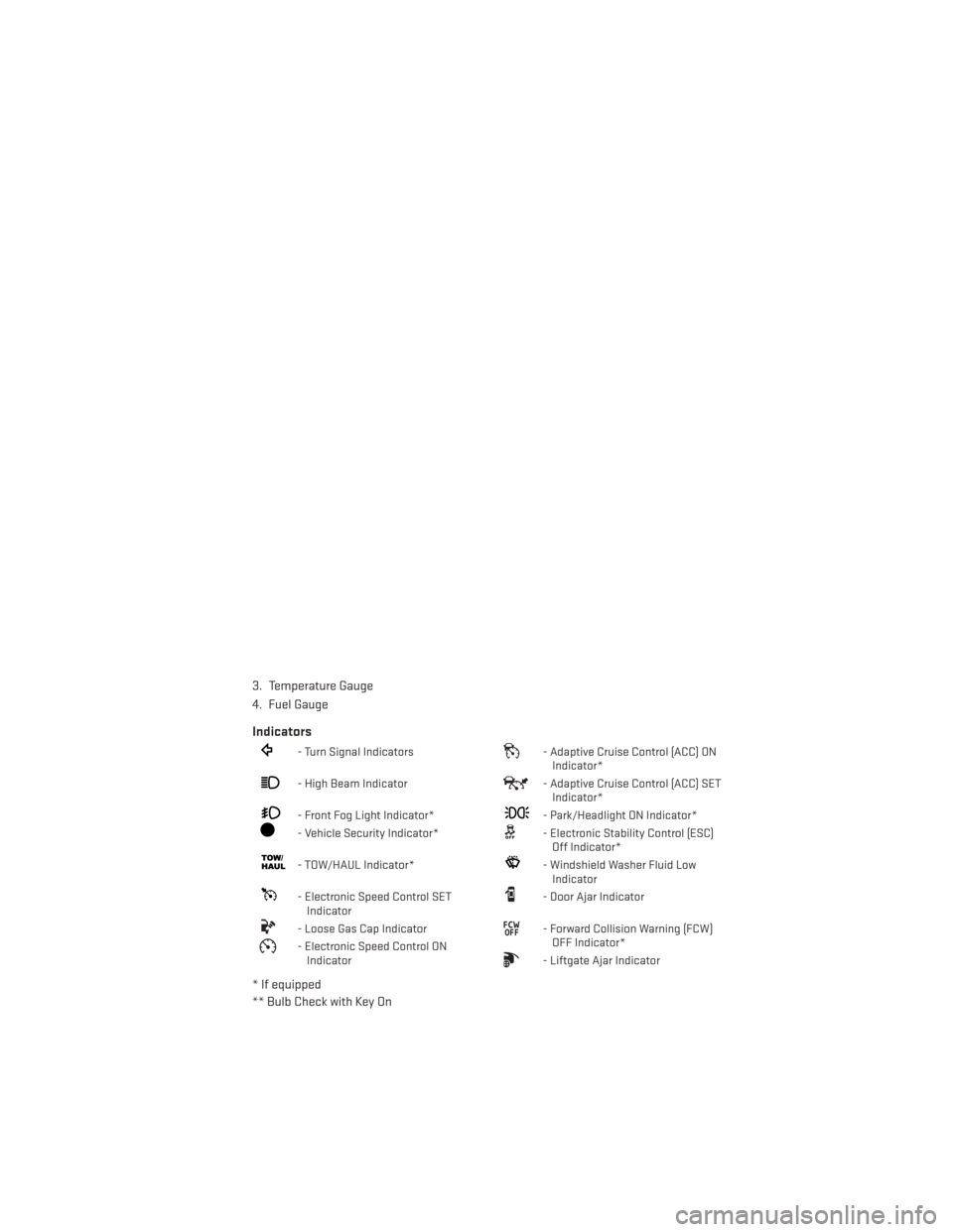
3. Temperature Gauge
4. Fuel Gauge
Indicators
- Turn Signal Indicators- Adaptive Cruise Control (ACC) ONIndicator*
- High Beam Indicator- Adaptive Cruise Control (ACC) SETIndicator*
- Front Fog Light Indicator*- Park/Headlight ON Indicator*
- Vehicle Security Indicator*- Electronic Stability Control (ESC)Off Indicator*
- TOW/HAUL Indicator*- Windshield Washer Fluid LowIndicator
- Electronic Speed Control SETIndicator- Door Ajar Indicator
- Loose Gas Cap Indicator- Forward Collision Warning (FCW)OFF Indicator*
- Electronic Speed Control ONIndicator- Liftgate Ajar Indicator
* If equipped
** Bulb Check with Key On
CONTROLS AT A GLANCE
9
Page 18 of 188
SUPPLEMENTAL RESTRAINT SYSTEM (SRS) — AIR BAGS
This vehicle has Advanced Front Air Bags for both the driver and front passenger as a
supplement to the seat belt restraint systems. The driver's Advanced Front Air Bag is
mounted in the center of the steering wheel. The passenger's Advanced Front Air Bag is
mounted in the instrument panel, above the glove compartment. The words SRS AIR BAG
are embossed on the air bag covers.
Advanced Front Air Bags are designed to provide additional protection by supplementing
the seat belts in certain frontal collisions depending on several factors, including the
severity and type of collision. Advanced Front Air Bags are not expected to reduce the risk
of injury in rear, side, or rollover collisions.
This vehicle is equipped with Supplemental Side Air Bag Inflatable Curtains to protect the
driver, front and rear passengers sitting next to a window.
This vehicle is equipped with Supplemental Seat-Mounted Side Air Bags to provide en-
hanced protection to help protect an occupant during a side impact.
This vehicle is equipped with Supplemental Driver’s Side Knee Air Bag mounted in the
instrument panel below the steering column and a Knee Bolster mounted below the glove
compartment. The Supplemental Driver’s Side Knee Air Bag provides enhanced protection
and works together with the Driver Advanced Front Air Bag during a frontal impact.
If the Air Bag Warning Light
is not on during starting, stays on, or turns on while driving,
have the vehicle serviced by an authorized service center immediately.
Refer to the Owner's Manual on the DVD for further details regarding the Supplemental
Restraint System (SRS).
WARNING!
• Relying on the air bags alone could lead to more severe injuries in a collision. The air bags work with your seat belt to restrain you properly. In some collisions, the air bags
won't deploy at all. Always wear your seat belts even though you have air bags.
• Being too close to the steering wheel or instrument panel during Advanced Front Air
Bag deployment could cause serious injury, including death. Air bags need room to
inflate. Sit back, comfortably extending your arms to reach the steering wheel or
instrument panel.
• Supplemental Side Air Bag Inflatable Curtains and Supplemental Seat-Mounted Side
Air Bags need room to inflate. Do not lean against the door or window. Sit upright in
the center of the seat.
•
Being too close to the Supplemental Side Air Bag Inflatable Curtain and/or Seat-
Mounted Side Air Bag during deployment could cause you to be severely injured or killed.
• Do not drive your vehicle after the air bags have deployed. If you are involved in
another collision, the air bags will not be in place to protect you.
• After any collision, the vehicle should be taken to an authorized dealer immediately.
GETTING STARTED
16
Page 48 of 188

BLIND SPOT MONITORING
The Blind Spot Monitoring (BSM) system uses two radar-based sensors, located inside the
rear bumper fascia, to detect Highway licensable vehicles (automobiles, trucks, motor-
cycles etc.) that enter the blind spot zones from the rear/front/side of the vehicle.
The Blind Spot Monitoring (BSM) system warning light, located in the outside mirrors, will
illuminate if a vehicle moves into a blind spot zone.
The BSM system can also be configured to sound an audible (chime) alert and mute the
radio to notify you of objects that have entered the detection zones.
Refer to your Owner's Manual on the DVD for further details.
POWER SUNROOF
The power sunroof switch is located on the overhead console.
Opening Sunroof
Express Open
• Press the switch rearward and release itwithin one-half second. The sunroof will
fully open and stop automatically.
Manual Open
• Press and hold the switch rearward to open the sunroof. Any release of the
switch will stop the movement, and the
sunroof will remain in a partially open
position until the switch is pressed again.
Venting Sunroof
• Press and release the button and the sun-roof will open to the vent position.
This is called “Express Vent” and will occur
regardless of sunroof position. During Ex-
press Vent operation, any movement of the
switch will stop the sunroof.
Power Sunroof Switch
1 — Opening Sunroof
2 — Venting Sunroof
3 — Closing Sunroof
OPERATING YOUR VEHICLE
46
Page 118 of 188
Compass Calibration
This compass is self-calibrating, which eliminates the need to set the compass manually.
When the vehicle is new, the compass may appear erratic and the EVIC will display “CAL”
until the compass is calibrated.
You may also calibrate the compass by completing one or more 360 degree turns (in an area
free from large metal or metallic objects) until the “CAL” message displayed in the EVIC
turns off. The compass will now function normally.
ECO
The ECO message will appear in your EVIC display whenever you are driving in a fuel
efficient manner.
This feature allows you to monitor when you are driving in a fuel efficient manner, and it can
be used to modify driving habits in order to increase fuel economy.
PROGRAMMABLE FEATURES
EVIC Programmable Features
The EVIC can be used to view the following main menu items:
NOTE:
Depending on the vehicles options, feature settings may vary.
• Speedometer• Trip
• MPH to km/h • Audio
• Vehicle Info • Stored Messages
• Driver Assist • Screen Setup
• Fuel Economy • Speed Warning - If Equipped
NOTE:
Refer to your Owner's Manual on the DVD for further information.
Uconnect® Customer Programmable Features
The Uconnect® system allows you to access Customer Programmable feature settings
such as Display, Clock, Safety/Assistance, Lights, Doors & Locks, Auto-On Comfort &
Remote Start, Engine Off Operation, Compass Settings, Audio, Trailer Brake, Phone/
Bluetooth®, Suspension and SiriusXM Setup and System Information through soft-keys.
• Press the SETTINGS button (Uconnect® 5.0), or press the “Apps” button (Uconnect® 8.4)
located near the bottom of the touchscreen, then press the “Settings” button on the
touchscreen to access the Settings screen. When making a selection, scroll up or down
until the preferred setting is highlighted, then press and release the preferred setting
until a check-mark appears next to the setting, showing that setting has been selected.
ELECTRONICS
116
Page 122 of 188
Using HomeLink®
• To operate, press and release the programmed HomeLink® button. Activation will nowoccur for the programmed device (e.g., garage door opener, gate operator, security
system, entry door lock, home/office lighting, etc.,). The hand-held transmitter of the
device may also be used at any time.
WARNING!
• Your motorized door or gate will open and close while you are programming the
universal transceiver. Do not program the transceiver if people or pets are in the path
of the door or gate.
• Do not run your vehicle in a closed garage or confined area while programming the
transceiver. Exhaust gas from your vehicle contains Carbon Monoxide (CO) which is
odorless and colorless. Carbon Monoxide is poisonous when inhaled and can cause
you and others to be severely injured or killed.
POWER INVERTER
There is a 115 Volt, 150 Watt power inverter outlet located on the back of the center console.
This outlet can power cellular phones, electronics and other low power devices requiring
power up to 150 Watts.
NOTE:
The power inverter is designed with built-in
overload protection. If the power rating of
150 Watts is exceeded, the power inverter
will automatically shut down. Once the elec-
trical device has been removed from the
outlet, the inverter should automatically re-
set. If the power rating exceeds approxi-
mately 170 Watts, the power inverter may
have to be reset manually. To reset the in-
verter manually, unplug the device and plug
it in again. To avoid overloading the circuit,
check the power ratings on electrical devices prior to using the inverter.
WARNING!
To Avoid Serious Injury or Death DO NOT:
• insert any objects into the receptacles
• touch with wet hands
Close the lid when not in use. If this outlet is mishandled, it may cause an electric shock
and failure.
ELECTRONICS
120
Page 125 of 188
ALL-WHEEL DRIVE OPERATION
Single-Speed Operating Instructions/Precautions
This system contains a single-speed (HI range only) transfer case, which provides conve-
nient full-time all-wheel drive. No driver interaction is required. The Brake Traction Control
(BTC) System, which combines standard ABS and Traction Control, provides resistance to
any wheel that is slipping to allow additional torque transfer to wheels with traction.
NOTE:
This system is not appropriate for conditions where AWD LOW range is recommended. Refer to
“Off-Road Driving Tips” in “Starting and Operating” on the DVD for further information.
Electronically Shifted Transfer Case (Three-Position Switch)
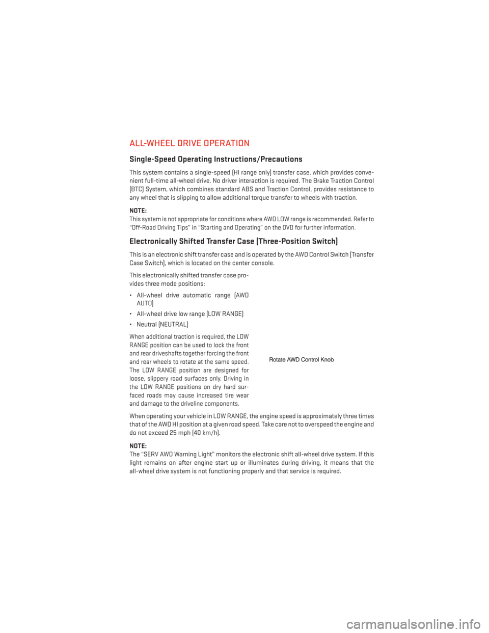
This is an electronic shift transfer case and is operated by the AWD Control Switch (Transfer
Case Switch), which is located on the center console.
This electronically shifted transfer case pro-
vides three mode positions:
• All-wheel drive automatic range (AWDAUTO)
• All-wheel drive low range (LOW RANGE)
• Neutral (NEUTRAL)
When additional traction is required, the LOW
RANGE position can be used to lock the front
and rear driveshafts together forcing the front
and rear wheels to rotate at the same speed.
The LOW RANGE position are designed for
loose, slippery road surfaces only. Driving in
the LOW RANGE positions on dry hard sur-
faced roads may cause increased tire wear
and damage to the driveline components.
When operating your vehicle in LOW RANGE, the engine speed is approximately three times
that of the AWD HI position at a given road speed. Take care not to overspeed the engine and
do not exceed 25 mph (40 km/h).
NOTE:
The “SERV AWD Warning Light” monitors the electronic shift all-wheel drive system. If this
light remains on after engine start up or illuminates during driving, it means that the
all-wheel drive system is not functioning properly and that service is required.
OFF-ROAD CAPABILITIES
123
Page 126 of 188
Shifting Procedures
AWD Auto To Low Range
NOTE:
When shifting into or out of LOW RANGE some gear noise may be heard. This noise is
normal and is not detrimental to the vehicle or occupants.
• Shifting can be performed with the vehicle rolling 2 to 3 mph (3 to 5 km/h) or completelystopped. Use either of the following procedures:
Preferred Procedure
1. With the engine running, slow the vehicle to 2 to 3 mph (3 to 5 km/h).
2. Shift the transmission into NEUTRAL.
3. While still rolling, rotate the transfer case control switch to the desired position.
4. After the desired position indicator light is ON (not flashing), shift the transmission back into gear.
Alternate Procedure
1. Bring the vehicle to complete stop.
2. With the ignition switch in the ON position and the engine either OFF or running, shift the transmission into NEUTRAL.
3. Rotate the transfer case control switch to the desired position.
4. After the desired position indicator light is ON (not flashing), shift the transmission back into gear.
NOTE:
• If Steps 1 or 2 of either the Preferred or Alternate Procedure are not satisfied prior to attempting the shift or if they no longer are being met while the shift attempt is in
process, the desired position indicator light will flash continuously while the original
position indicator light is ON, until all requirements have been met.
• The ignition switch must be in the ON position for a shift to take place and for the position indicator lights to be operable. If the ignition switch is not in the ON position, then the
shift will not take place and no position indicator lights will be on or flashing.
WARNING!
• Always engage the parking brake when powering down the vehicle if the “SERV AWD
Warning Light” is illuminated. Not engaging the parking brake may allow the vehicle
to roll which may cause personal injury.
•
You or others could be injured if you leave the vehicle unattended with the transfer case
in the NEUTRAL position without first fully engaging the parking brake. The transfer case
NEUTRAL position disengages both the front and rear driveshafts from the powertrain
and will allow the vehicle to move regardless of the transmission position. The parking
brake should always be applied when the driver is not in the vehicle.
OFF-ROAD CAPABILITIES
124
Page 131 of 188
NOTE:
• Steps 1 through 3 are requirements that must be met before pressing the NEUTRAL (N)button, and must continue to be met until the shift has been completed. If any of these
requirements are not met before pressing the NEUTRAL (N) button or are no longer met
during the shift, the NEUTRAL (N) indicator light will flash continuously until all require-
ments are met or until the NEUTRAL (N) button is released.
• The ignition switch must be in the ON/RUN position for a shift to take place and for the position indicator lights to be operable. If the ignition switch is not in the ON/RUN
position, the shift will not take place and no position indicator lights will be on or flashing.
• A flashing NEUTRAL (N) position indicator light indicates that shift requirements have not been met.
CAUTION!
•Towing with the rear wheels on the ground will cause severe transmission damage.
Damage from improper towing is not covered under the New Vehicle Limited Warranty.
• Front or rear wheel lifts should not be used. Internal damage to the transmission or
transfer case will occur if a front or rear wheel lift is used when recreational towing.
• It is necessary to follow these steps to be certain that the transfer case is fully in NEUTRAL before recreational towing to prevent damage to internal parts.
WARNING!
You or others could be injured if you leave the vehicle unattended with the transfer case
in the NEUTRAL position without first fully engaging the parking brake. The transfer case
NEUTRAL position disengages both the front and rear driveshafts from the powertrain
and will allow the vehicle to move even if the transmission is in PARK. The parking brake
should always be applied when the driver is not in the vehicle.
UTILITY
129