light DODGE DURANGO 2015 3.G Owner's Guide
[x] Cancel search | Manufacturer: DODGE, Model Year: 2015, Model line: DURANGO, Model: DODGE DURANGO 2015 3.GPages: 236, PDF Size: 35.01 MB
Page 156 of 236
Using HomeLink®
To o p e r a t e , p u s h a n d r e l e a s e t h e p r o g r a m m e d H o m e L i n k®button. Activation will now
occur for the programmed device (e.g., garage door opener, gate operator, security system,
entry door lock, home/office lighting, etc.). The hand-held transmitter of the device may
also be used at any time.
WARNING!
•Yourmotorizeddoororgatewillopenandclosewhileyouareprogrammingthe
universal transceiver. Do not program the transceiver if people or pets are in the
path of the door or gate.
•Donotrunyourvehicleinaclosedgarageorconfinedareawhileprogrammingthe
transceiver. Exhaust gas from your vehicle contains Carbon Monoxide (CO) which is
odorless and colorless. Carbon Monoxide is poisonous when inhaled and can cause
you and others to be severely injured or killed.
POWER INVERTER
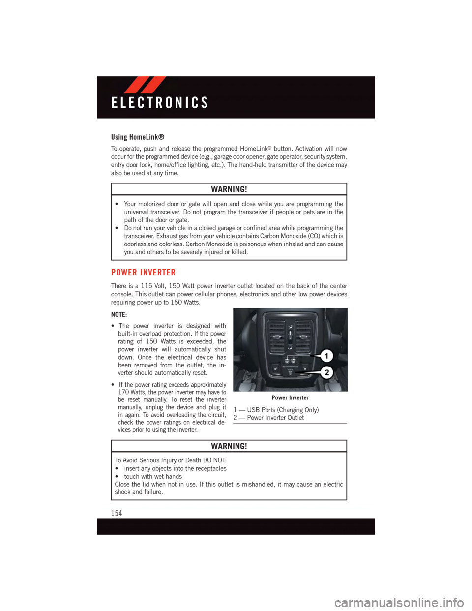
There is a 115 Volt, 150 Watt power inverter outlet located on the back of the center
console. This outlet can power cellular phones, electronics and other low power devices
requiring power up to 150 Watts.
NOTE:
•Thepowerinverterisdesignedwith
built-in overload protection. If the power
rating of 150 Watts is exceeded, the
power inverter will automatically shut
down. Once the electrical device has
been removed from the outlet, the in-
verter should automatically reset.
•If the power rating exceeds approximately170 Watts, the power inverter may have tobe reset manually. To reset the invertermanually, unplug the device and plug itin again. To avoid overloading the circuit,check the power ratings on electrical de-vices prior to using the inverter.
WARNING!
To A v o i d S e r i o u s I n j u r y o r D e a t h D O N O T:
•insertanyobjectsintothereceptacles
•touchwithwethands
Close the lid when not in use. If this outlet is mishandled, it may cause an electric
shock and failure.
Power Inverter
1—USBPorts(ChargingOnly)2—PowerInverterOutlet
ELECTRONICS
154
Page 158 of 236
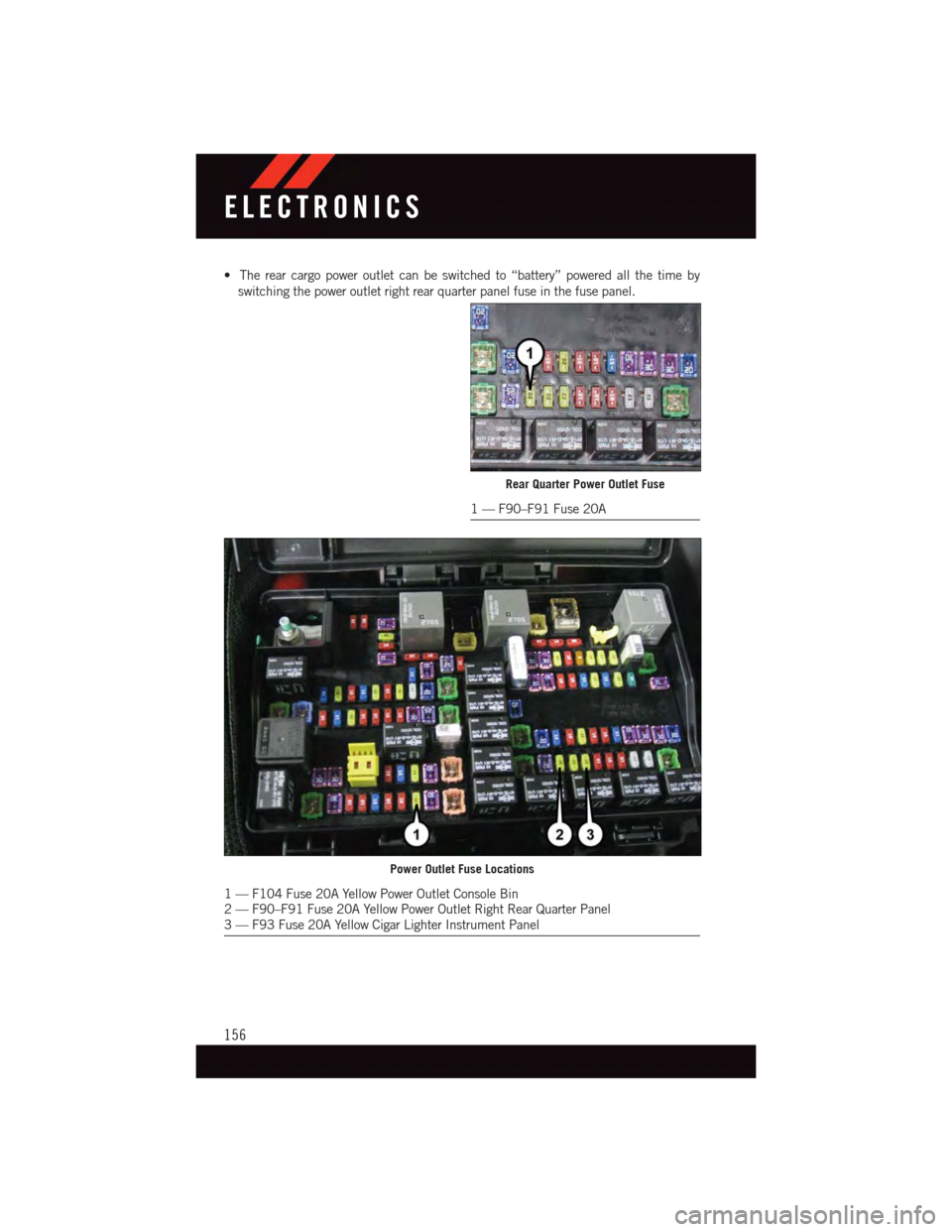
•Therearcargopoweroutletcanbeswitchedto“battery”poweredallthetimeby
switching the power outlet right rear quarter panel fuse in the fuse panel.
Rear Quarter Power Outlet Fuse
1—F90–F91Fuse20A
Power Outlet Fuse Locations
1—F104Fuse20AYellowPowerOutletConsoleBin2—F90–F91Fuse20AYellowPowerOutletRightRearQuarterPanel3—F93Fuse20AYellowCigarLighterInstrumentPanel
ELECTRONICS
156
Page 159 of 236
ALL-WHEEL DRIVE OPERATION
Single-Speed Operating Instructions/Precautions
This system contains a single-speed (HI range only) transfer case, which provides
convenient full-time all-wheel drive. No driver interaction is required. The Brake Traction
Control (BTC) System, which combines standard ABS and Traction Control, provides
resistance to any wheel that is slipping to allow additional torque transfer to wheels with
traction.
NOTE:
This system is not appropriate for conditions where AWD LOW range is recommended. Refer
to “Off-Road Driving Tips” in “Starting and Operating” on the DVD for further information.
Electronically Shifted Transfer Case (Three-Position Switch)
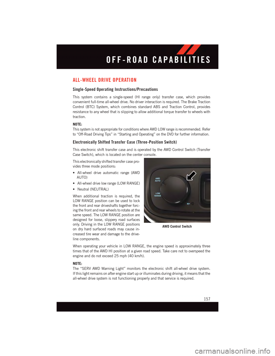
This electronic shift transfer case and is operated by the AWD Control Switch (Transfer
Case Switch), which is located on the center console.
This electronically shifted transfer case pro-
vides three mode positions:
•All-wheeldriveautomaticrange(AWD
AUTO)
•All-wheeldrivelowrange(LOWRANGE)
•Neutral(NEUTRAL)
When additional traction is required, the
LOW RANGE position can be used to lock
the front and rear driveshafts together forc-
ing the front and rear wheels to rotate at the
same speed. The LOW RANGE position are
designed for loose, slippery road surfaces
only. Driving in the LOW RANGE positions
on dry hard surfaced roads may cause in-
creased tire wear and damage to the drive-
line components.
When operating your vehicle in LOW RANGE, the engine speed is approximately three
times that of the AWD HI position at a given road speed. Take care not to overspeed the
engine and do not exceed 25 mph (40 km/h).
NOTE:
The “SERV AWD Warning Light” monitors the electronic shift all-wheel drive system.
If this light remains on after engine start up or illuminates during driving, it means that the
all-wheel drive system is not functioning properly and that service is required.
AWD Control Switch
OFF-ROAD CAPABILITIES
157
Page 160 of 236
Shifting Procedures
AWD Auto To Low Range
NOTE:
When shifting into or out of LOW RANGE some gear noise may be heard. This noise is
normal and is not detrimental to the vehicle or occupants.
•Shiftingcanbeperformedwiththevehiclerolling2to3mph(3to5km/h)or
completely stopped. Use either of the following procedures:
Preferred Procedure
1. With the engine running, slow the vehicle to 2 to 3 mph (3 to 5 km/h).
2. Shift the transmission into NEUTRAL.
3. While still rolling, rotate the transfer case control switch to the desired position.
4. After the desired position indicator light is ON (not flashing), shift the transmission
back into gear.
Alternate Procedure
1. Bring the vehicle to complete stop.
2. With the ignition switch in the ON position and the engine either OFF or running, shift
the transmission into NEUTRAL.
3. Rotate the transfer case control switch to the desired position.
4. After the desired position indicator light is ON (not flashing), shift the transmission
back into gear.
NOTE:
•IfSteps1or2ofeitherthePreferredorAlternateProcedurearenotsatisfiedpriorto
attempting the shift or if they no longer are being met while the shift attempt is in
process, the desired position indicator light will flash continuously while the original
position indicator light is ON, until all requirements have been met.
•TheignitionswitchmustbeintheONpositionforashifttotakeplaceandforthe
position indicator lights to be operable. If the ignition switch is not in the ON position,
then the shift will not take place and no position indicator lights will be on or flashing.
OFF-ROAD CAPABILITIES
158
Page 161 of 236
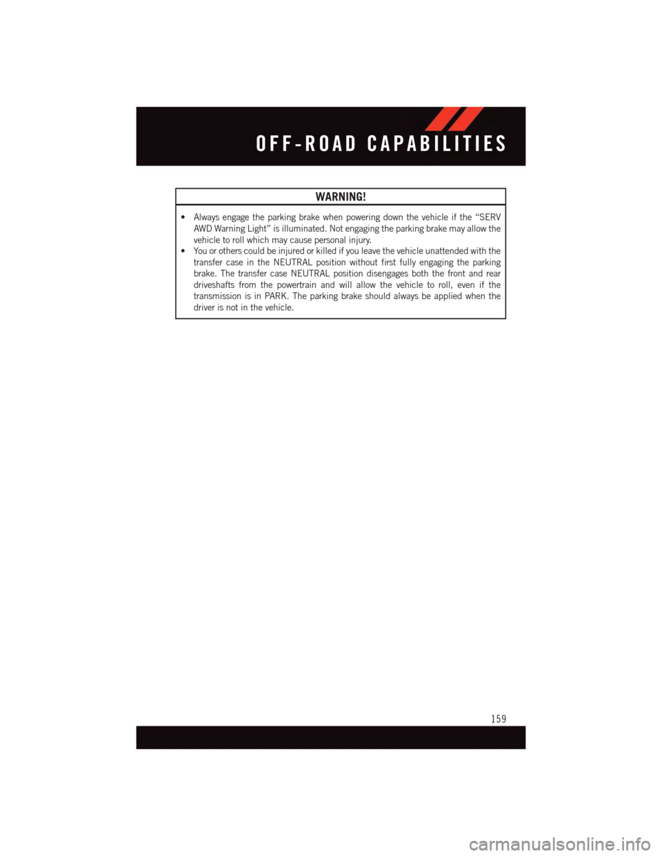
WARNING!
•Alwaysengagetheparkingbrakewhenpoweringdownthevehicleifthe“SERV
AWD Warning Light” is illuminated. Not engaging the parking brake may allow the
vehicle to roll which may cause personal injury.
•Youorotherscouldbeinjuredorkilledifyouleavethevehicleunattendedwiththe
transfer case in the NEUTRAL position without first fully engaging the parking
brake. The transfer case NEUTRAL position disengages both the front and rear
driveshafts from the powertrain and will allow the vehicle to roll, even if the
transmission is in PARK. The parking brake should always be applied when the
driver is not in the vehicle.
OFF-ROAD CAPABILITIES
159
Page 163 of 236
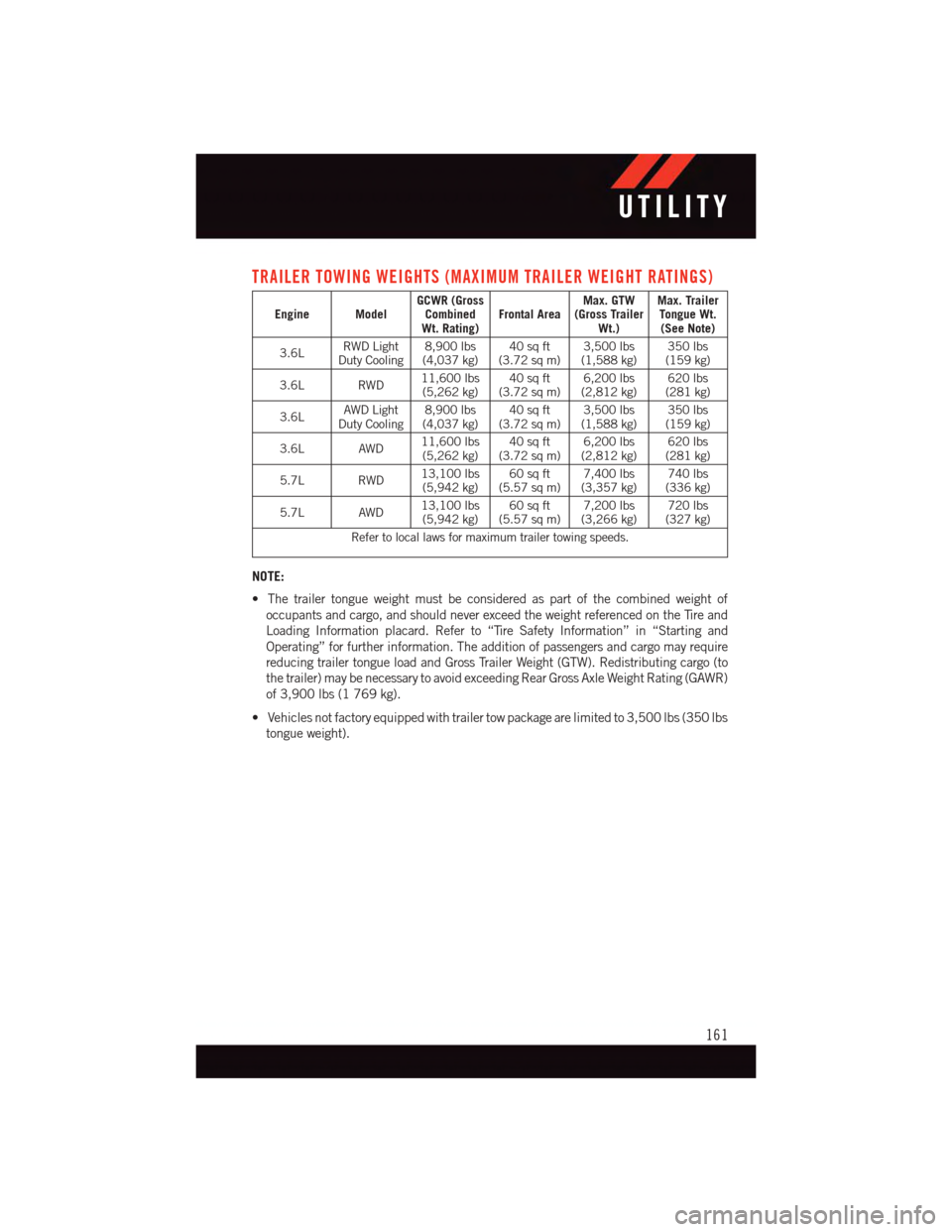
TRAILER TOWING WEIGHTS (MAXIMUM TRAILER WEIGHT RATINGS)
Engine ModelGCWR (GrossCombinedWt. Rating)Frontal AreaMax. GTW(Gross TrailerWt.)
Max. TrailerTongue Wt.(See Note)
3.6LRWD LightDuty Cooling8,900 lbs(4,037 kg)40 sq ft(3.72 sq m)3,500 lbs(1,588 kg)350 lbs(159 kg)
3.6L RWD11,600 lbs(5,262 kg)40 sq ft(3.72 sq m)6,200 lbs(2,812 kg)620 lbs(281 kg)
3.6LAWD LightDuty Cooling8,900 lbs(4,037 kg)40 sq ft(3.72 sq m)3,500 lbs(1,588 kg)350 lbs(159 kg)
3.6L AWD11,600 lbs(5,262 kg)40 sq ft(3.72 sq m)6,200 lbs(2,812 kg)620 lbs(281 kg)
5.7L RWD13,100 lbs(5,942 kg)60 sq ft(5.57 sq m)7,400 lbs(3,357 kg)740 lbs(336 kg)
5.7L AWD13,100 lbs(5,942 kg)60 sq ft(5.57 sq m)7,200 lbs(3,266 kg)720 lbs(327 kg)
Refer to local laws for maximum trailer towing speeds.
NOTE:
•Thetrailertongueweightmustbeconsideredaspartofthecombinedweightof
occupants and cargo, and should never exceed the weight referenced on the Tire and
Loading Information placard. Refer to “Tire Safety Information” in “Starting and
Operating” for further information. The addition of passengers and cargo may require
reducing trailer tongue load and Gross Trailer Weight (GTW). Redistributing cargo (to
the trailer) may be necessary to avoid exceeding Rear Gross Axle Weight Rating (GAWR)
of 3,900 lbs (1 769 kg).
•Vehiclesnotfactoryequippedwithtrailertowpackagearelimitedto3,500lbs(350lbs
tongue weight).
UTILITY
161
Page 167 of 236
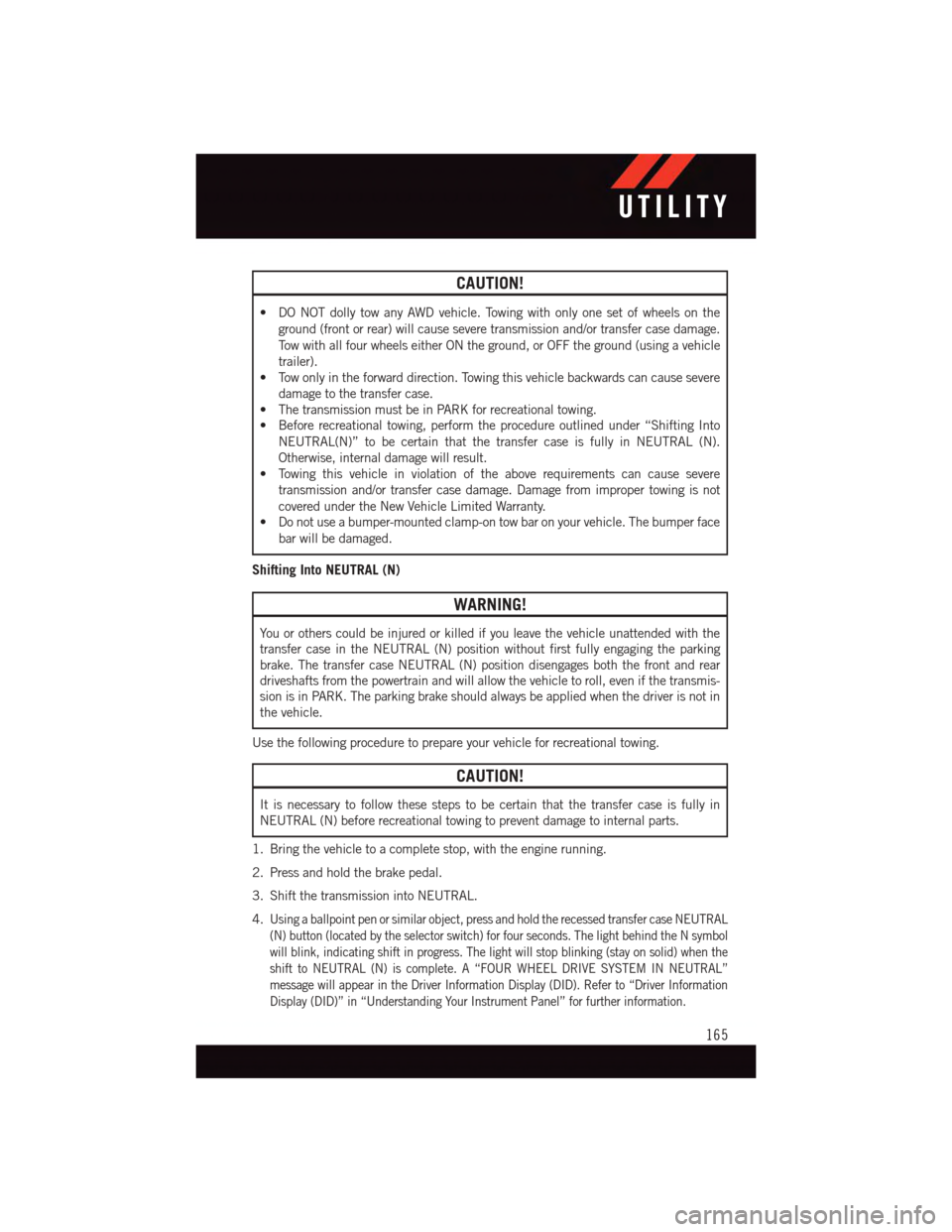
CAUTION!
•DONOTdollytowanyAWDvehicle.Towingwithonlyonesetofwheelsonthe
ground (front or rear) will cause severe transmission and/or transfer case damage.
To w w i t h a l l f o u r w h e e l s e i t h e r O N t h e g r o u n d , o r O F F t h e g r o u n d ( u s i n g a v e h i c l e
trailer).
•Towonlyintheforwarddirection.Towingthisvehiclebackwardscancausesevere
damage to the transfer case.
•ThetransmissionmustbeinPARKforrecreationaltowing.
•Beforerecreationaltowing,performtheprocedureoutlinedunder“ShiftingInto
NEUTRAL(N)” to be certain that the transfer case is fully in NEUTRAL (N).
Otherwise, internal damage will result.
•Towingthisvehicleinviolationoftheaboverequirementscancausesevere
transmission and/or transfer case damage. Damage from improper towing is not
covered under the New Vehicle Limited Warranty.
•Donotuseabumper-mountedclamp-ontowbaronyourvehicle.Thebumperface
bar will be damaged.
Shifting Into NEUTRAL (N)
WARNING!
Yo u o r o t h e r s c o u l d b e i n j u r e d o r k i l l e d i f y o u l e a v e t h e v e h i c l e u n a t t e n d e d w i t h t h e
transfer case in the NEUTRAL (N) position without first fully engaging the parking
brake. The transfer case NEUTRAL (N) position disengages both the front and rear
driveshafts from the powertrain and will allow the vehicle to roll, even if the transmis-
sion is in PARK. The parking brake should always be applied when the driver is not in
the vehicle.
Use the following procedure to prepare your vehicle for recreational towing.
CAUTION!
It is necessary to follow these steps to be certain that the transfer case is fully in
NEUTRAL (N) before recreational towing to prevent damage to internal parts.
1. Bring the vehicle to a complete stop, with the engine running.
2. Press and hold the brake pedal.
3. Shift the transmission into NEUTRAL.
4.Using a ballpoint pen or similar object, press and hold the recessed transfer case NEUTRAL
(N) button (located by the selector switch) for four seconds. The light behind the N symbol
will blink, indicating shift in progress. The light will stop blinking (stay on solid) when the
shift to NEUTRAL (N) is complete. A “FOUR WHEEL DRIVE SYSTEM IN NEUTRAL”
message will appear in the Driver Information Display (DID). Refer to “Driver Information
Display (DID)” in “Understanding Your Instrument Panel” for further information.
UTILITY
165
Page 168 of 236
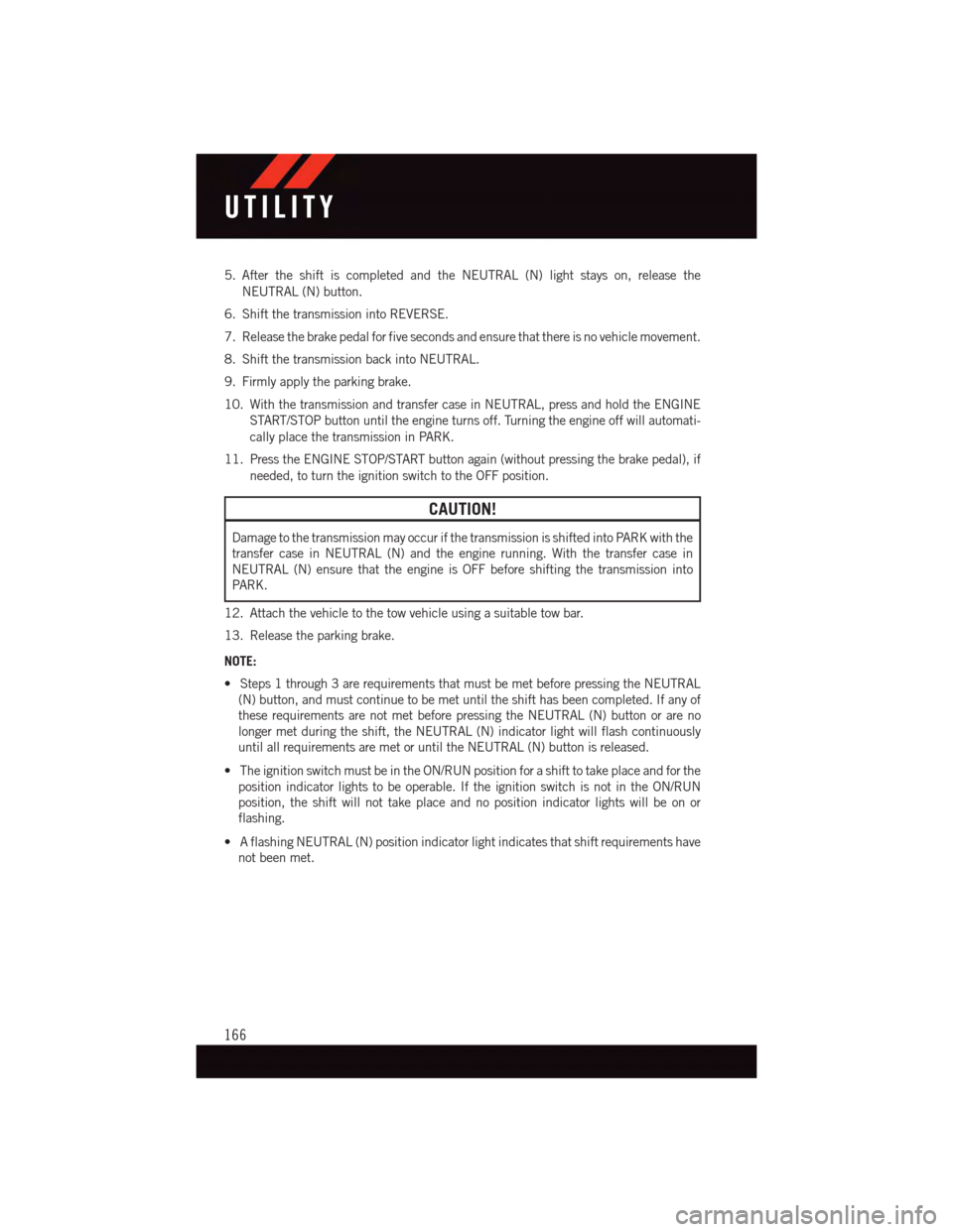
5. After the shift is completed and the NEUTRAL (N) light stays on, release the
NEUTRAL (N) button.
6. Shift the transmission into REVERSE.
7. Release the brake pedal for five seconds and ensure that there is no vehicle movement.
8. Shift the transmission back into NEUTRAL.
9. Firmly apply the parking brake.
10. With the transmission and transfer case in NEUTRAL, press and hold the ENGINE
START/STOP button until the engine turns off. Turning the engine off will automati-
cally place the transmission in PARK.
11. Press the ENGINE STOP/START button again (without pressing the brake pedal), if
needed, to turn the ignition switch to the OFF position.
CAUTION!
Damage to the transmission may occur if the transmission is shifted into PARK with the
transfer case in NEUTRAL (N) and the engine running. With the transfer case in
NEUTRAL (N) ensure that the engine is OFF before shifting the transmission into
PA R K .
12. Attach the vehicle to the tow vehicle using a suitable tow bar.
13. Release the parking brake.
NOTE:
•Steps1through3arerequirementsthatmustbemetbeforepressingtheNEUTRAL
(N) button, and must continue to be met until the shift has been completed. If any of
these requirements are not met before pressing the NEUTRAL (N) button or are no
longer met during the shift, the NEUTRAL (N) indicator light will flash continuously
until all requirements are met or until the NEUTRAL (N) button is released.
•TheignitionswitchmustbeintheON/RUNpositionforashifttotakeplaceandforthe
position indicator lights to be operable. If the ignition switch is not in the ON/RUN
position, the shift will not take place and no position indicator lights will be on or
flashing.
•AflashingNEUTRAL(N)positionindicatorlightindicatesthatshiftrequirementshave
not been met.
UTILITY
166
Page 169 of 236
Shifting Out Of NEUTRAL (N)
Use the following procedure to prepare your vehicle for normal usage.
1. Bring the vehicle to a complete stop, leaving it connected to the tow vehicle.
2. Firmly apply the parking brake.
3. Start the engine.
4. Press and hold the brake pedal.
5. Shift the transmission into NEUTRAL.
6. Using a ballpoint pen or similar object, press and hold the recessed transfer case
NEUTRAL (N) button (located by the selector switch) for one second.
7. When the NEUTRAL (N) indicator light turns off, release the NEUTRAL (N) button.
8. After the NEUTRAL (N) button has been released, the transfer case will shift to the
position indicated by the selector switch.
9. Shift the transmission into PARK and turn the engine OFF.
10. Release the brake pedal.
11. Disconnect vehicle from the tow vehicle.
12. Start the engine.
13. Press and hold the brake pedal.
14. Release the parking brake.
15. Shift the transmission into DRIVE, release the brake pedal, and check that the
vehicle operates normally.
NOTE:
•Steps1through5arerequirementsthatmustbemetbeforepressingtheNEUTRAL
(N) button, and must continue to be met until the shift has been completed. If any of
these requirements are not met before pressing the NEUTRAL (N) button or are no
longer met during the shift, the NEUTRAL (N) indicator light will flash continuously
until all requirements are met or until the NEUTRAL (N) button is released.
•TheignitionswitchmustbeintheON/RUNpositionforashifttotakeplaceandforthe
position indicator lights to be operable. If the ignition switch is not in the ON/RUN
position, the shift will not take place and no position indicator lights will be on or
flashing.
•AflashingNEUTRAL(N)positionindicatorlightindicatesthatshiftrequirementshave
not been met.
UTILITY
167
Page 170 of 236
ROADSIDE ASSISTANCE
Dial toll-free 1-800-521-2779 for U.S. Residents or 1-800-363-4869 for Canadian
Residents.
•Provideyourname,vehicleidentificationnumber,licenseplatenumber,andyour
location, including the telephone number from which you are calling.
•Brieflydescribethenatureoftheproblemandanswerafewsimplequestions.
•Youwillbegiventhenameoftheserviceproviderandanestimatedtimeofarrival.
If you feel you are in an “unsafe situation”, please let us know. With your consent, we
will contact local police or safety authorities.
INSTRUMENT CLUSTER WARNING LIGHTS
-TirePressureMonitoringSystem(TPMS)Light
Each tire, including the spare (if provided), should be checked monthly, when cold and
inflated to the inflation pressure recommended by the vehicle manufacturer on the
vehicle placard or tire inflation pressure label. (If your vehicle has tires of a different size
than the size indicated on the vehicle placard or tire inflation pressure label, you should
determine the proper tire inflation pressure for those tires.)
As an added safety feature, your vehicle has been equipped with a Tire Pressure
Monitoring System (TPMS) which display in the Electronic Vehicle Information Center
(EVIC) or Driver Information Display (DID) when one or more of your tires is significantly
under-inflated. Accordingly, when the low tire pressure EVIC or DID display illuminates,
you should stop and check your tires as soon as possible, and inflate them to the proper
pressure. Driving on a significantly under-inflated tire causes the tire to overheat and can
lead to tire failure. Under-inflation also reduces fuel efficiency and tire tread life, and may
affect the vehicle’s handling and stopping ability.
IF THE LIGHT STARTS FLASHING INDICATING A LOW TIRE PRESSURE, ADJUST THE AIR
PRESSURE IN THE LOW TIRE TO THE AIR PRESSURE SHOWN ON THE VEHICLE PLACARD OR
TIRE INFLATION PRESSURE LABEL LOCATED ON THE DRIVER'S DOOR.
NOTE:
After inflation, the vehicle may need to be driven for 20 minutes before the flashing light
will turn off.
Please note that the TPMS is not a substitute for proper tire maintenance, and it is the
driver’s responsibility to maintain correct tire pressure, even if under-inflation has not
reached the level to trigger illumination of the TPMS low EVIC or DID display.
Yo u r v e h i c l e h a s a l s o b e e n e q u i p p e d w i t h a T P M S m a l f u n c t i o n i n d i c a t o r t o i n d i c a t e w h e n
the system is not operating properly. The TPMS malfunction indicator is combined with
the low tire pressure telltale. When the system detects a malfunction, the telltale will flash
for approximately one minute and then remain continuously illuminated. This sequence
will continue each time the vehicle is restarted as long as the malfunction exists.
WHAT TO DO IN EMERGENCIES
168