light DODGE DURANGO 2015 3.G Service Manual
[x] Cancel search | Manufacturer: DODGE, Model Year: 2015, Model line: DURANGO, Model: DODGE DURANGO 2015 3.GPages: 236, PDF Size: 35.01 MB
Page 171 of 236
When the malfunction indicator is illuminated, the system may not be able to detect or signal
low tire pressure as intended. TPMS malfunctions may occur for a variety of reasons,
including the installation of replacement or alternate tires or wheels on the vehicle that
prevent the TPMS from functioning properly. Always check the TPMS malfunction telltale
after replacing one or more tires or wheels on your vehicle, to ensure that the replacement or
alternate tires and wheels allow the TPMS to continue to function properly.
NOTE:
Ti r e p r e s s u r e s c h a n g e b y a p p r o x i m a t e l y 1 p s i ( 7 k P a ) p e r 1 2 ° F ( 7 ° C ) o f a i r t e m p e r a t u r e
change. Keep this in mind when checking tire pressure inside a garage, especially in the
Winter. Example: If garage temperature is 68°F (20°C) and the outside temperature is
32°F (0°C), then the cold tire inflation pressure should be increased by 3 psi (21 kPa),
which equals 1 psi (7 kPa) for every 12°F (7°C) for this outside temperature condition.
CAUTION!
The TPMS has been optimized for the original equipment tires and wheels. TPMS
pressures and warning have been established for the tire size equipped on your vehicle.
Undesirable system operation or sensor damage may result when using replacement
equipment that is not of the same size, type, and/or style. Aftermarket wheels can
cause sensor damage. Do not use tire sealant from a can, or balance beads if your
vehicle is equipped with a TPMS, as damage to the sensors may result.
Brake Warning Light
This light monitors various brake functions, including brake fluid level and parking brake
application. If the brake light turns on, it may indicate that the parking brake is applied,
that the brake fluid level is low, or that there is a problem with the anti-lock brake system
reservoir.
If the light remains on when the parking brake has been disengaged, and the fluid level is
at the full mark on the master cylinder reservoir, it indicates a possible brake hydraulic
system malfunction or that a problem with the Brake Booster has been detected by the
Anti-Lock Brake System (ABS)/Electronic Stability Control (ESC) system. In this case, the
light will remain on until the condition has been corrected. If the problem is related to the
brake booster, the ABS pump will run when applying the brake, and a brake pedal
pulsation may be felt during each stop.
The dual brake system provides a reserve braking capacity in the event of a failure to a
portion of the hydraulic system. A leak in either half of the dual brake system is indicated
by the Brake Warning Light, which will turn on when the brake fluid level in the master
cylinder has dropped below a specified level. The light will remain on until the cause is
corrected.
WHAT TO DO IN EMERGENCIES
169
Page 172 of 236
Vehicles equipped with the Anti-Lock Brake System (ABS) are also equipped with
Electronic Brake Force Distribution (EBD). In the event of an EBD failure, the Brake
Warning Light will turn on along with the ABS Light. Immediate repair to the ABS system
is required.
Operation of the Brake Warning Light can be checked by turning the ignition switch from
the OFF position to the ON/RUN position. The light should illuminate for approximately
two seconds. The light should then turn off unless the parking brake is applied or a brake
fault is detected. If the light does not illuminate, have the light inspected by an authorized
dealer.
The light also will turn on when the parking brake is applied with the ignition switch in the
ON/RUN position.
NOTE:
This light shows only that the parking brake is applied. It does not show the degree of
brake application.
WARNING!
Driving a vehicle with the red brake light on is dangerous. Part of the brake system may
have failed. It will take longer to stop the vehicle. You could have a collision. Have the
vehicle checked immediately.
-MalfunctionIndicatorLight(MIL)
The Malfunction Indicator Light (MIL) is part of an onboard diagnostic system called
OBD II that monitors engine and automatic transmission control systems. The light will
illuminate when the key is in the ON/RUN position before engine start. If the bulb does not
come on when turning the key from OFF to ON/RUN, have the condition checked
promptly.
Certain conditions, poor fuel quality, etc., may illuminate the light after engine start. The
vehicle should be serviced if the light stays on through several of your typical driving
cycles. In most situations, the vehicle will drive normally and will not require towing.
CAUTION!
Prolonged driving with the Malfunction Indicator Light (MIL) on could cause damage
to the engine control system. It also could affect fuel economy and driveability. If the
MIL is flashing, severe catalytic converter damage and power loss will soon occur.
Immediate service is required.
WHAT TO DO IN EMERGENCIES
170
Page 173 of 236
WARNING!
Amalfunctioningcatalyticconverter,asreferencedabove,canreachhighertempera-
tures than in normal operating conditions. This can cause a fire if you drive slowly or
park over flammable substances such as dry plants, wood, cardboard, etc. This could
result in death or serious injury to the driver, occupants or others.
-ElectronicStabilityControl(ESC)Activation/MalfunctionIndicatorLight
The “ESC Activation/Malfunction Indicator Light” in the instrument cluster will come on
when the ignition switch is turned to the ON/RUN position. It should go out with the
engine running. If the “ESC Activation/Malfunction Indicator Light” comes on continu-
ously with the engine running, a malfunction has been detected in the ESC system. If this
light remains on after several ignition cycles, and the vehicle has been driven several miles
(kilometers) at speeds greater than 30 mph (48 km/h), see your authorized dealer as soon
as possible to have the problem diagnosed and corrected.
NOTE:
•The“ESCOffIndicatorLight”andthe“ESCActivation/MalfunctionIndicatorLight”
come on momentarily each time the ignition switch is turned to ON/RUN.
•EachtimetheignitionisturnedtoON/RUN,theESCsystemwillbeON,evenifitwas
turned off previously.
•TheESCsystemwillmakebuzzingorclickingsoundswhenitisactive.Thisisnormal;
the sounds will stop when ESC becomes inactive following the maneuver that caused
the ESC activation.
•Toimprovethevehicle'stractionwhenstartingoffindeepsnow,sandorgravel,itmay
be desirable to switch the ESC system to Partial Off mode by momentarily pressing the
ESC Offswitch located below the climate controls, on the switch panel.
-ChargingSystemLight
This light shows the status of the electrical charging system. If the charging system light
remains on, it means that the vehicle is experiencing a problem with the charging system.
We recommend you do not continue driving if the charging system light is on. Have the
vehicle serviced immediately.
-OilPressureWarningLight
This light indicates low engine oil pressure. If the light turns on while driving, stop the
vehicle and shut off the engine as soon as possible. A chime will sound for four minutes
when this light turns on.
We recommend you do not operate the vehicle or engine damage will occur. Have the
vehicle serviced immediately.
WHAT TO DO IN EMERGENCIES
171
Page 174 of 236
-Anti-LockBrake(ABS)Light
This light monitors the Anti-Lock Brake System (ABS). The light will turn on when the
ignition switch is turned to the ON/RUN position and may stay on for as long as four
seconds.
If the ABS light remains on or turns on while driving, it indicates that the Anti-Lock portion
of the brake system is not functioning and that service is required. However, the
conventional brake system will continue to operate normally if the BRAKE warning light is
not on.
If the ABS light is on, the brake system should be serviced as soon as possible to restore
the benefits of Anti-Lock brakes. If the ABS light does not turn on when the ignition switch
is turned to the ON/RUN position, have the light inspected by an authorized dealer.
-ElectronicThrottleControl(ETC)Light
This light informs you of a problem with the Electronic Throttle Control (ETC) system.
If a problem is detected, the light will come on while the engine is running. Cycle the
ignition key when the vehicle has completely stopped and the shift lever/gear selector is
placed in the PARK position; the light should turn off.
If the light remains lit with the engine running, your vehicle will usually be drivable.
However, see an authorized service center immediately. If the light is flashing when the
engine is running, immediate service is required and you may experience reduced
performance, an elevated/rough idle or engine stall and your vehicle may require towing.
-AirBagWarningLight
This light will turn on for four to eight seconds as a bulb check when the ignition switch
is first turned to the ON/RUN position. If the light is either not on during starting, stays on,
or turns on while driving, have the system inspected at an authorized dealer as soon as
possible. Refer to “Occupant Restraints” in “Things To Know Before Starting Your
Vehicle” in your Owner’s Manual on the DVD for further information.
NOTE:
The Air Bag System is designed to be maintenance free.
WHAT TO DO IN EMERGENCIES
172
Page 175 of 236
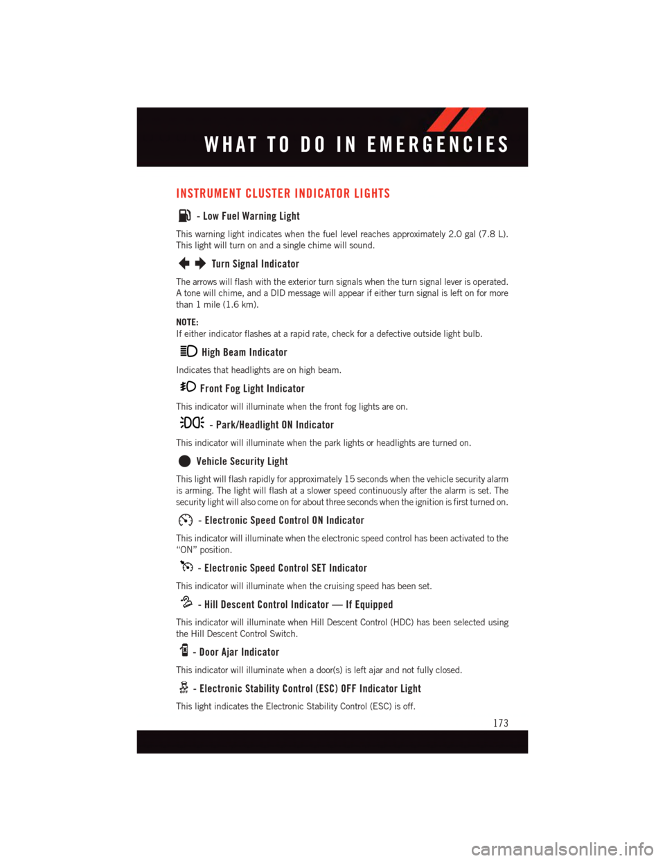
INSTRUMENT CLUSTER INDICATOR LIGHTS
-LowFuelWarningLight
This warning light indicates when the fuel level reaches approximately 2.0 gal (7.8 L).
This light will turn on and a single chime will sound.
Turn Signal Indicator
The arrows will flash with the exterior turn signals when the turn signal lever is operated.
Atonewillchime,andaDIDmessagewillappearifeitherturnsignalisleftonformore
than 1 mile (1.6 km).
NOTE:
If either indicator flashes at a rapid rate, check for a defective outside light bulb.
High Beam Indicator
Indicates that headlights are on high beam.
Front Fog Light Indicator
This indicator will illuminate when the front fog lights are on.
-Park/HeadlightONIndicator
This indicator will illuminate when the park lights or headlights are turned on.
Vehicle Security Light
This light will flash rapidly for approximately 15 seconds when the vehicle security alarm
is arming. The light will flash at a slower speed continuously after the alarm is set. The
security light will also come on for about three seconds when the ignition is first turned on.
-ElectronicSpeedControlONIndicator
This indicator will illuminate when the electronic speed control has been activated to the
“ON” position.
-ElectronicSpeedControlSETIndicator
This indicator will illuminate when the cruising speed has been set.
-HillDescentControlIndicator—IfEquipped
This indicator will illuminate when Hill Descent Control (HDC) has been selected using
the Hill Descent Control Switch.
-DoorAjarIndicator
This indicator will illuminate when a door(s) is left ajar and not fully closed.
-ElectronicStabilityControl(ESC)OFFIndicatorLight
This light indicates the Electronic Stability Control (ESC) is off.
WHAT TO DO IN EMERGENCIES
173
Page 183 of 236
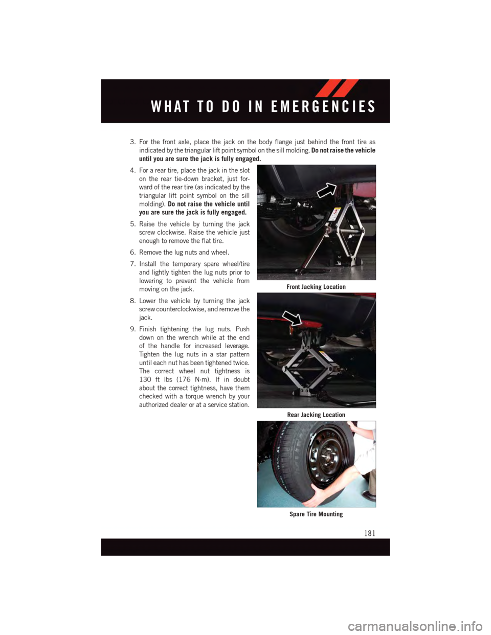
3. For the front axle, place the jack on the body flange just behind the front tire as
indicated by the triangular lift point symbol on the sill molding.Do not raise the vehicle
until you are sure the jack is fully engaged.
4. For a rear tire, place the jack in the slot
on the rear tie-down bracket, just for-
ward of the rear tire (as indicated by the
triangular lift point symbol on the sill
molding).Do not raise the vehicle until
you are sure the jack is fully engaged.
5. Raise the vehicle by turning the jack
screw clockwise. Raise the vehicle just
enough to remove the flat tire.
6. Remove the lug nuts and wheel.
7. Install the temporary spare wheel/tire
and lightly tighten the lug nuts prior to
lowering to prevent the vehicle from
moving on the jack.
8. Lower the vehicle by turning the jack
screw counterclockwise, and remove the
jack.
9. Finish tightening the lug nuts. Push
down on the wrench while at the end
of the handle for increased leverage.
Ti g h t e n t h e l u g n u t s i n a s t a r p a t t e r n
until each nut has been tightened twice.
The correct wheel nut tightness is
130 ft lbs (176 N·m). If in doubt
about the correct tightness, have them
checked with a torque wrench by your
authorized dealer or at a service station.
Front Jacking Location
Rear Jacking Location
Spare Tire Mounting
WHAT TO DO IN EMERGENCIES
181
Page 186 of 236
Road Tire Installation
1. Mount the road tire on the axle.
2. Install the remaining lug nuts with the cone shaped end of the nut toward the wheel.
Lightly tighten the lug nuts.
3. Lower the vehicle to the ground by turning the jack handle counterclockwise.
4. Finish tightening the lug nuts. Push down on the wrench while at the end of the handle
for increased leverage. Tighten the lug nuts in a star pattern until each nut has been
tightened twice. The correct tightness of each lug nut is 130 ft/lbs (176 N·m). If in
doubt about the correct tightness, have them checked with a torque wrench by your
authorized dealer or service station.
5. After 25 miles (40 km) check the lug nut torque with a torque wrench to ensure that
all lug nuts are properly seated against the wheel.
CAUTION!
•Donotusepowertoolstowinchthetireupordown.Impacttypetoolscandamage
the winch mechanism.
•Donotattempttoraisethevehiclebyjackingonlocationsotherthanthose
indicated in the Jacking Instructions for this vehicle.
•Besuretomountthesparetirewiththevalvestemfacingoutward.Thevehicle
could be damaged if the spare tire is mounted incorrectly.
WHAT TO DO IN EMERGENCIES
184
Page 203 of 236
MAINTENANCE PROCEDURES
For information on the maintenance procedures for your vehicle, please refer to “Main-
tenance Procedures” in “Maintaining Your Vehicle” in your Owner’s Manual or applicable
supplement on the DVD for further details.
MAINTENANCE SCHEDULE
Yo u r v e h i c l e i s e q u i p p e d w i t h a n a u t o m a t i c o i l c h a n g e i n d i c a t o r s y s t e m . T h e o i l c h a n g e
indicator system will remind you that it is time to take your vehicle in for scheduled
maintenance.
Based on engine operation conditions, the oil change indicator message will illuminate.
This means that service is required for your vehicle. Operating conditions such as frequent
short-trips, trailer tow, extremely hot or cold ambient temperatures, and E85 fuel usage
will influence when the “Oil Change Required” message is displayed. Severe Operating
Conditions can cause the change oil message to illuminate as early as 3,500 miles
(5,600 km) since last reset. Have your vehicle serviced as soon as possible, within the
next 500 miles (805 km).
Yo u r a u t h o r i z e d d e a l e r w i l l r e s e t t h e o i l c h a n g e i n d i c a t o r m e s s a g e a f t e r c o m p l e t i n g t h e
scheduled oil change.
NOTE:
Under no circumstances should oil change intervals exceed 10,000 miles (16,000 km)
or twelve months, whichever comes first.
Severe Duty All Models
•ChangeEngineOilat4000miles(6,500km)ifthevehicleisoperatedinadustyand
off road environment. This type of vehicle use is considered Severe Duty.
Once A Month Or Before A Long Trip:
•Checkengineoillevel
•Checkwindshieldwasherfluidlevel
•Checkthetireinflationpressuresandlookforunusualwearordamage
•Check the fluid levels of the coolant reservoir, brake master cylinder and power steering,
and fill as needed.
•Checkfunctionofallinteriorandexteriorlights
MAINTAINING YOUR VEHICLE
201
Page 208 of 236
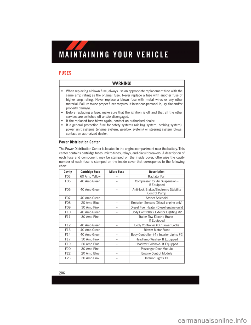
FUSES
WARNING!
•Whenreplacingablownfuse,alwaysuseanappropriatereplacementfusewiththe
same amp rating as the original fuse. Never replace a fuse with another fuse of
higher amp rating. Never replace a blown fuse with metal wires or any other
material. Failure to use proper fuses may result in serious personal injury, fire and/or
property damage.
•Beforereplacingafuse,makesurethattheignitionisoffandthatalltheother
services are switched off and/or disengaged.
•Ifthereplacedfuseblowsagain,contactanauthorizeddealer.
•Ifageneralprotectionfuseforsafetysystems(airbagsystem,brakingsystem),
power unit systems (engine system, gearbox system) or steering system blows,
contact an authorized dealer.
Power Distribution Center
The Power Distribution Center is located in the engine compartment near the battery. This
center contains cartridge fuses, micro fuses, relays, and circuit breakers. A description of
each fuse and component may be stamped on the inside cover, otherwise the cavity
number of each fuse is stamped on the inside cover that corresponds to the following
chart.
Cavity Cartridge Fuse Micro FuseDescription
F03 60 Amp Yellow –Radiator Fan
F05 40 Amp Green –Compressor for Air Suspension -If Equipped
F06 40 Amp Green – Anti-lock Brakes/Electronic StabilityControl Pump
F07 40 Amp Green –Starter Solenoid
F08 20 Amp Blue–EmissionSensors(Dieselengineonly)
F09 30 Amp Pink–DieselFuelHeater(Dieselengineonly)
F10 40 Amp Green – Body Controller / Exterior Lighting #2
F11 30 Amp Pink–Tr a i l e r To w E l e c t r i c B r a k e -If Equipped
F12 40 Amp Green –Body Controller #3 / Power Locks
F13 40 Amp Green –Blower Motor Front
F14 40 Amp Green – Body Controller #4 / Interior Lights #2
F17 30 Amp Pink–Headlamp Washer- If Equipped
F19 20 Amp Blue–Headrest Solenoid- If Equipped
F20 30 Amp Pink–Passenger Door Module
F22 20 Amp Blue–Engine Control Module
F23 30 Amp Pink–Interior Lights #1
MAINTAINING YOUR VEHICLE
206
Page 209 of 236
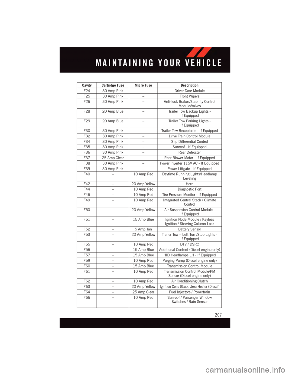
Cavity Cartridge Fuse Micro FuseDescription
F24 30 Amp Pink–Driver Door Module
F25 30 Amp Pink–Front Wipers
F26 30 Amp Pink–Anti-lock Brakes/Stability ControlModule/Valves
F28 20 Amp Blue–Tr a i l e r To w B a c k u p L i g h t s -If Equipped
F29 20 Amp Blue–Tr a i l e r To w P a r k i n g L i g h t s -If Equipped
F30 30 Amp Pink–TrailerTowReceptacle-IfEquipped
F32 30 Amp Pink–Drive Train Control Module
F34 30 Amp Pink–Slip Differential Control
F35 30 Amp Pink–Sunroof - If Equipped
F36 30 Amp Pink–Rear Defroster
F37 25 Amp Clear –Rear Blower Motor - If Equipped
F38 30 Amp Pink–PowerInverter115VAC-IfEquipped
F39 30 Amp Pink–Power Liftgate - If Equipped
F40–10 Amp Red Daytime Running Lights/HeadlampLeveling
F42–20AmpYellowHorn
F44–10 Amp RedDiagnostic Port
F46–10 Amp Red Tire Pressure Monitor - If Equipped
F49–10 Amp Red Integrated Central Stack / ClimateControl
F50–20AmpYellowAirSuspensionControlModule-If Equipped
F51–15 Amp Blue Ignition Node Module / KeylessIgnition / Steering Column Lock
F52–5AmpTanBattery Sensor
F53–20AmpYellowTrailerTow–LeftTurn/StopLights-If Equipped
F55–10 Amp RedDTV / DSRC
F56–15 Amp Blue Additional Content (Diesel engine only)
F57–15 Amp Blue HID Headlamps LH - If Equipped
F59–10 Amp Red Purging Pump (Diesel engine only)
F60–15 Amp Blue Transmission Control Module
F61–10 Amp Red Transmission Control Module/PMSensor (Diesel engine only)
F62–10 Amp Red Air Conditioning Clutch
F63–20AmpYellowIgnition Coils (Gas), Urea Heater (Diesel)
F64–25AmpClearFuelInjectors/Powertrain
F66–10 Amp Red Sunroof / Passenger WindowSwitches / Rain Sensor
MAINTAINING YOUR VEHICLE
207